Week 5 Bending of iPhone
Understanding the Bending of an IPhone and calculate Fatigue Life Using ANSYS Workbench
Objective: simulate the bending of the Iphone as per given cases below
Case1- Simulate the model as it given in the Video
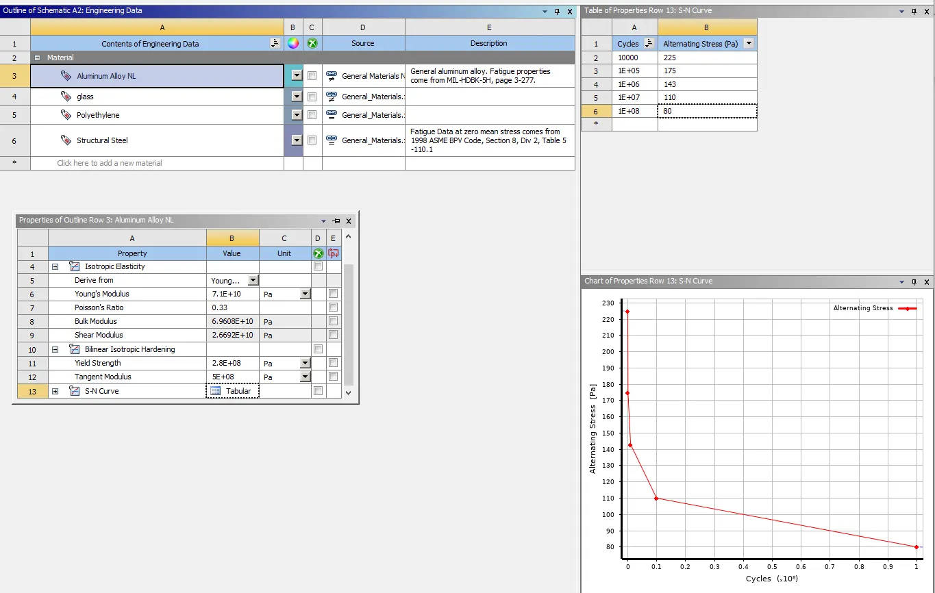
Case2- move the bottom finger from their defined to the given position X=22.5mm and Z=10mm and obtain the results for the simulation .Also define the S-N curve for the Aluminum Alloy Material as per value given below and determine the Fatigue life results for the same
Simulation Process:
Input Geometry
- The given module was inserted into the mechanical GUI.
- The I phone CAD model is imported into the Design modeller which is one of the geometry editor of Ansys
- The model is generated and checked if any abnormalities are present in the model
- The I phone CAD model model consist of different bodies which are renamed accordingly as upper finger, pushing fingers, frame, inner and display
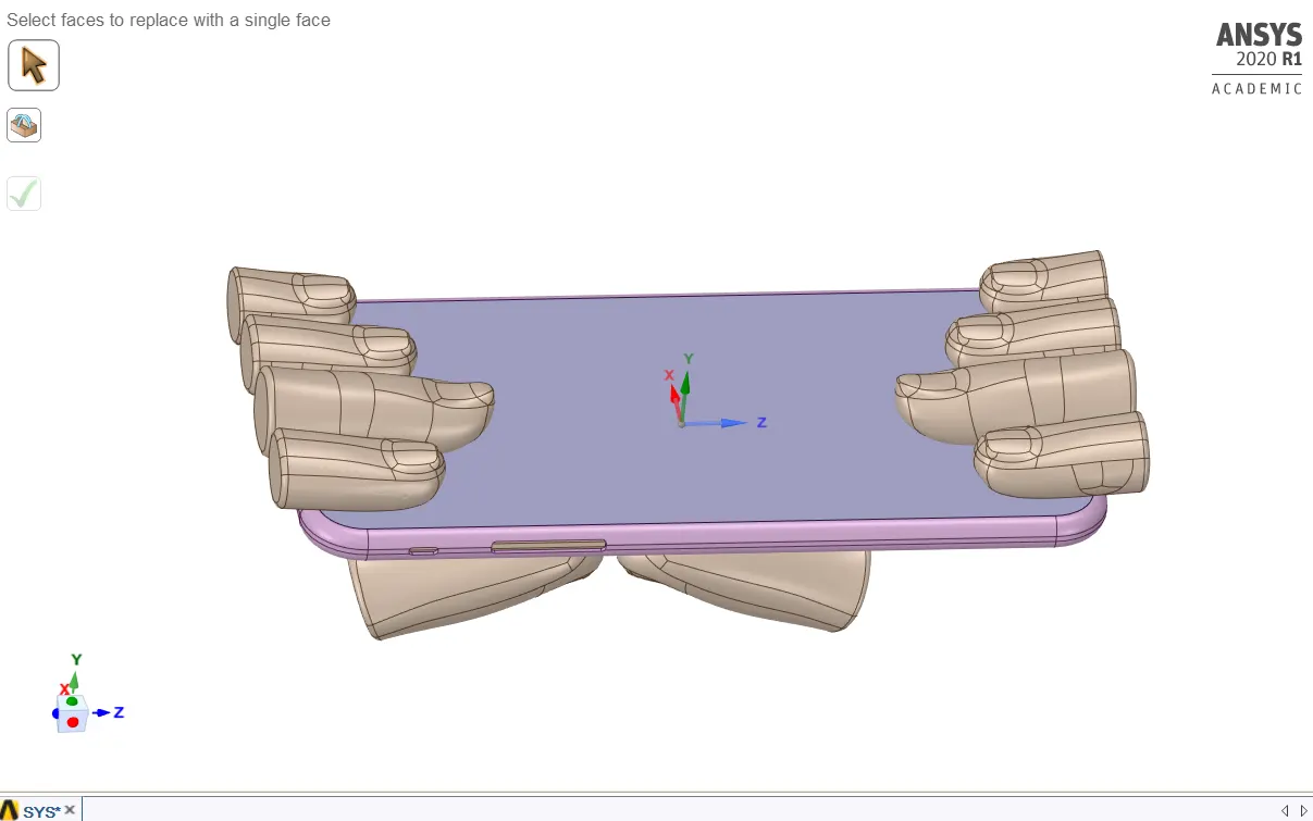
- merger the mulyiple surface in finger
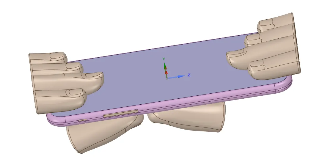
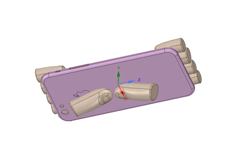
For case2, the pushing finger are subjected to body translational movement to bring their positions to the middle of the frame
Hence a translational displacement of X=22.5mm and Z=10 mm is given to set the pushing fingers at the middle position.
Material:
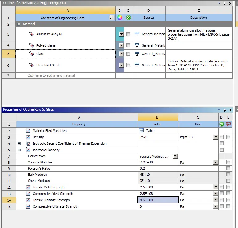
- In Mechanical tab, the bodies of I phone model are assignment with different materials
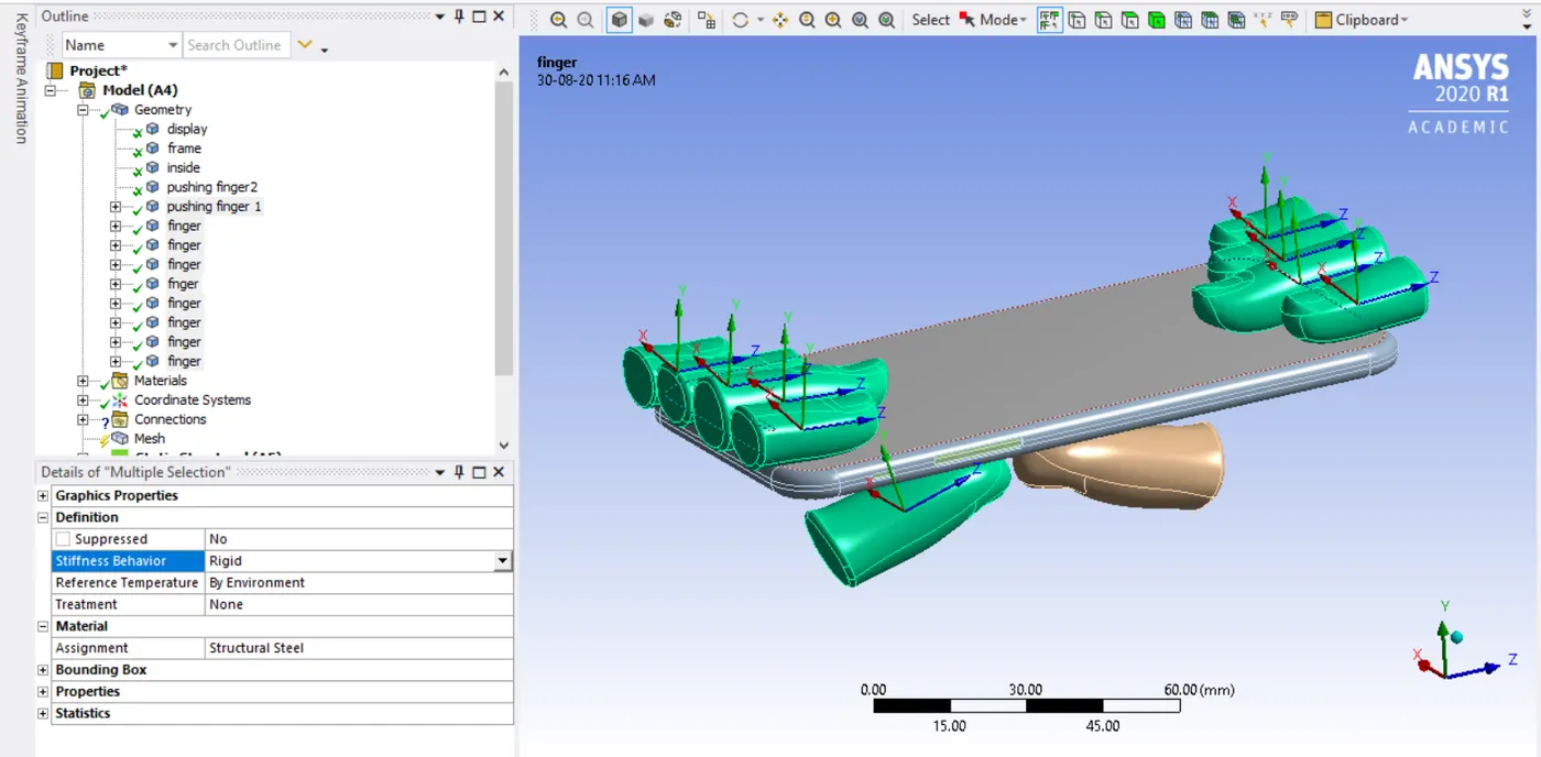
- The upper fingers and the pushing finger are assigned with structural steel material as their behaviour is set to be rigid
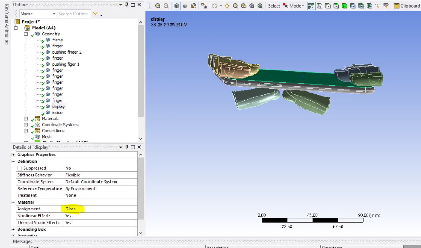
- The display of the iphone is assigned with glass material
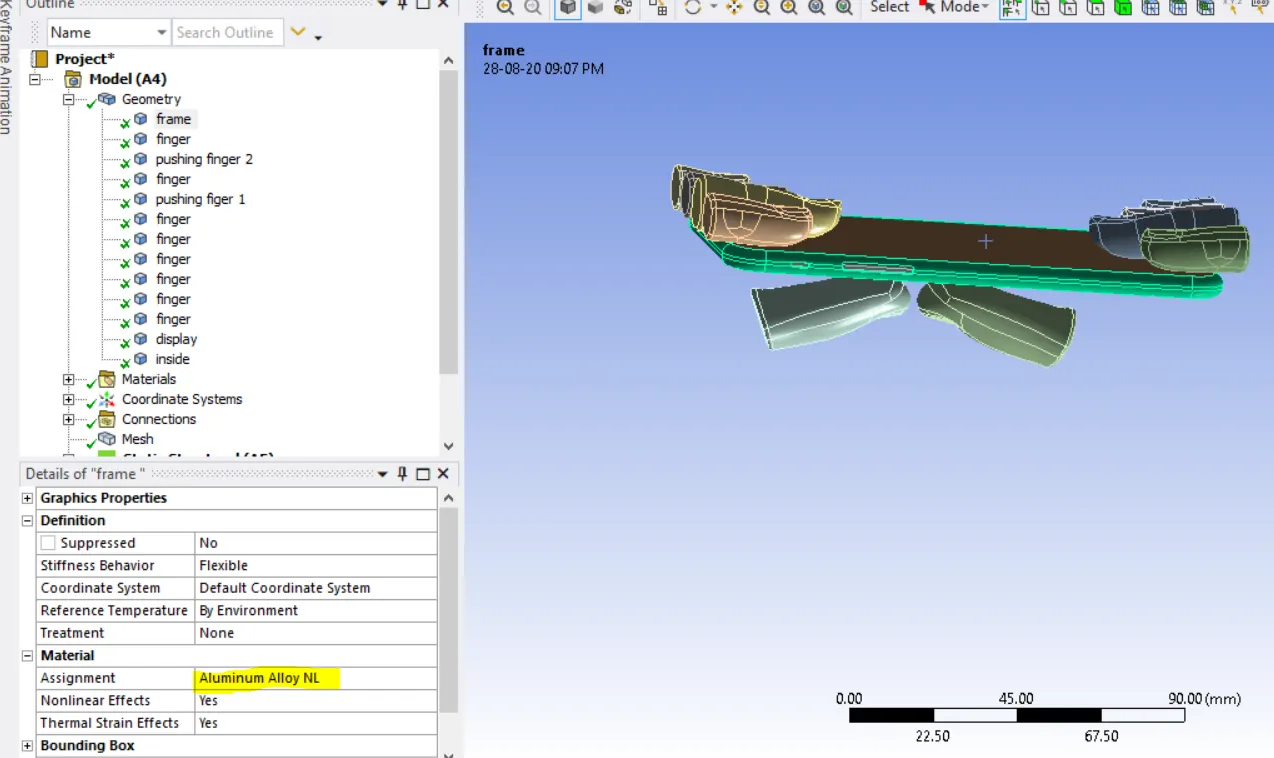
- The frame of the iphone is assigned with Aluminium alloy NL material
- The inner body of the Iphone is assigned with polyethylene material
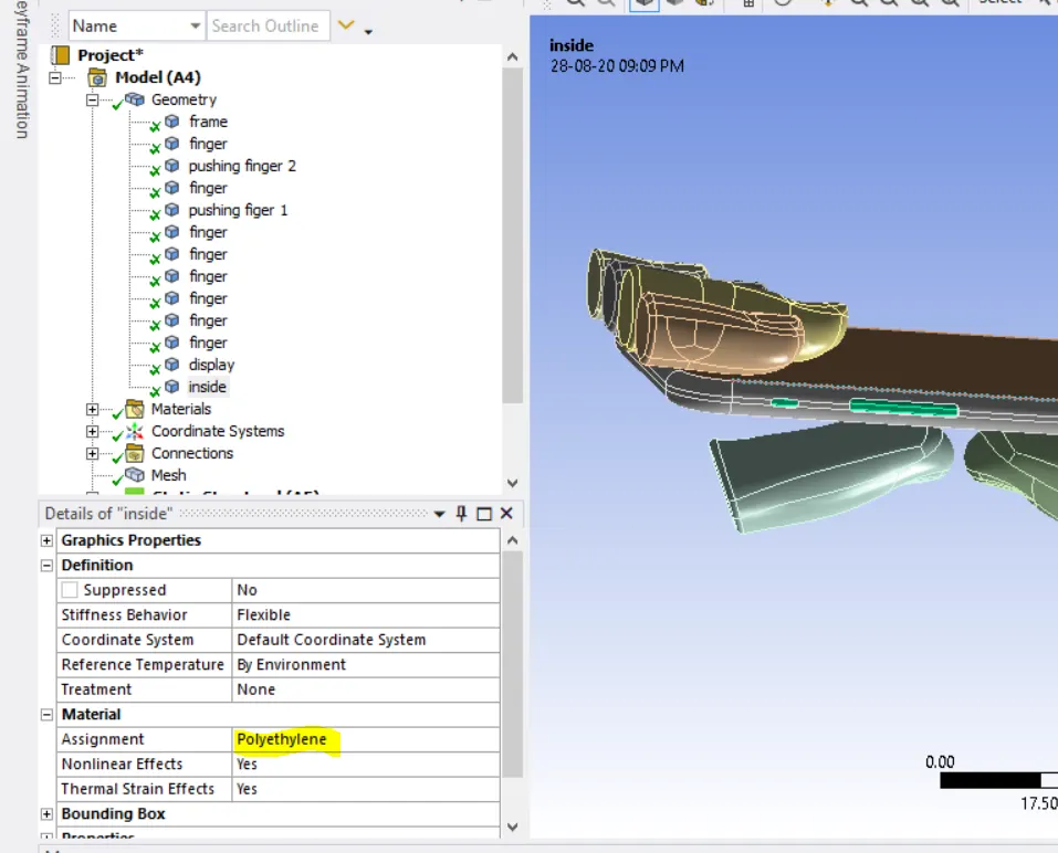
Contacts:
- Frictionless contact type is created for each and every contacts between fingers and the frame of Iphone .
- Bonded contact type is created between display and frame of iphone
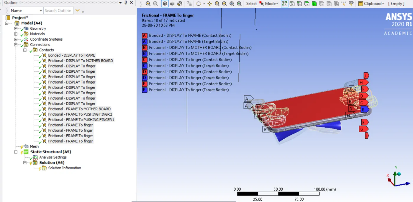
Joints:
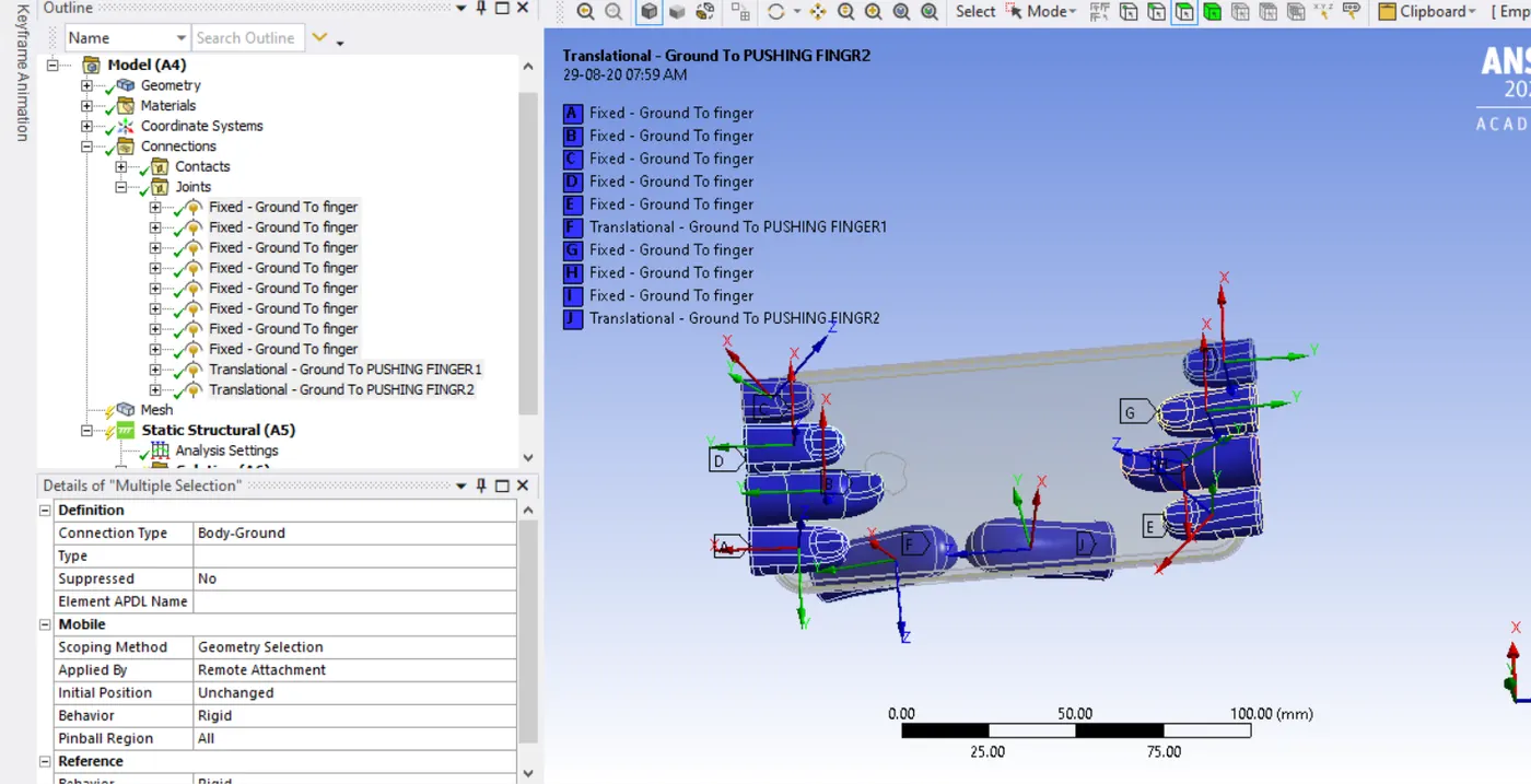
- The upper fingers are defined with a fixed Body –Ground Joint as they should not move from their positions.
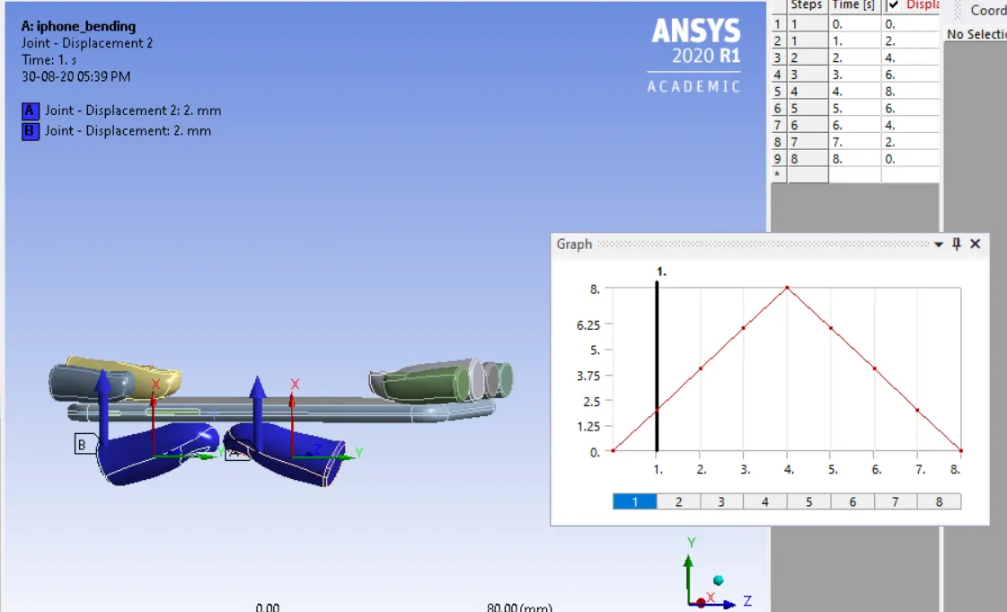
- The bottom pushing fingers are defined with a translational Body – Ground Joint as they tend to give a displacement for bending
- The reference co-ordinate systems for the pushing Fingers are adjusted is such a way that both are aligned in same displacement direction
Meshing
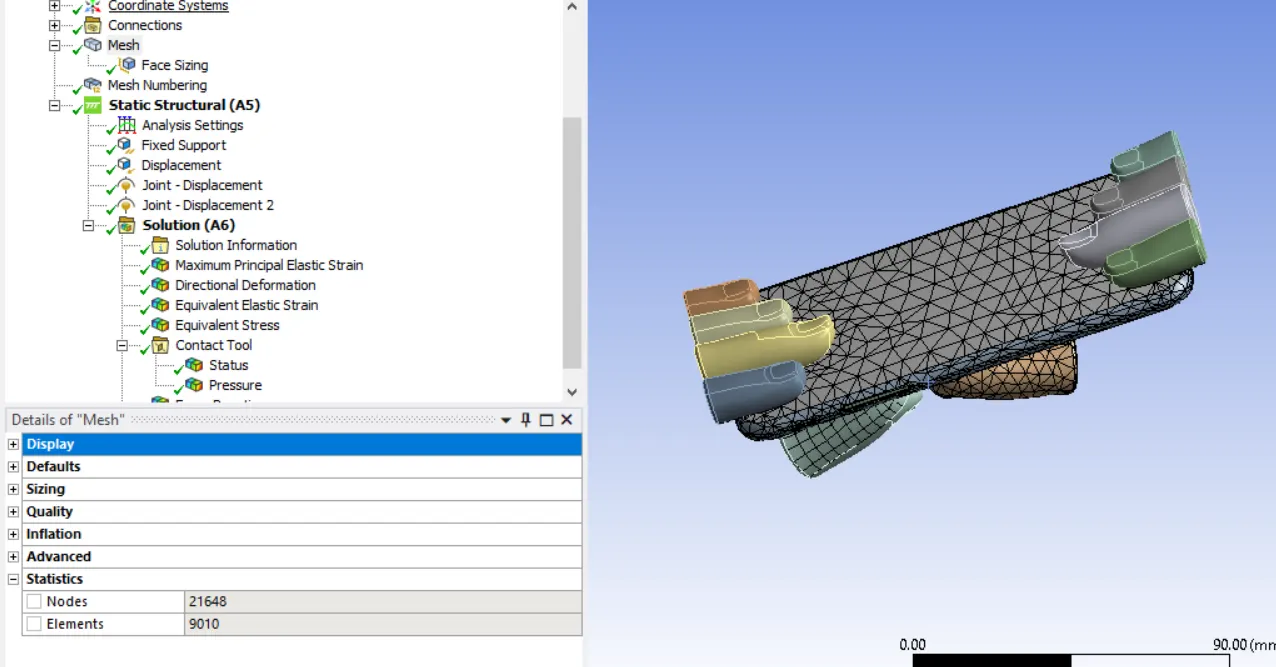
- A default mesh Size of 4mm with tetra element is used for the analysis.
- The adaptive mesh size is tuned off is turned off in order not to capture the feature as they are not our interested regions.
Analysis setting:
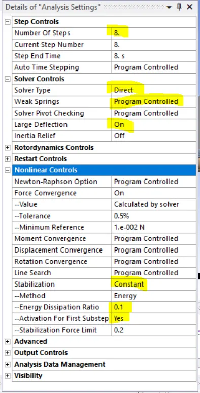
- The simulations are set to run for 8 steps.
- Large deformations is turned on in order to account for non-linear deformations
- The solver type is set to Direct
- The stabilizations limit is set to constant with an energy dissipations ratio of 0.2
Boundary conditions
- A fixed support is created at the two longitudinally opposite faces of the Iphone frame as the frame should not fly away during simulations
- for the lateral opposite faces of the frame , only free displacement is allowed only in the direction of bending
- Displacement in other directions are set to zero
- The bottom pushing finger are defined with joint loads with displacement of 2mm per step
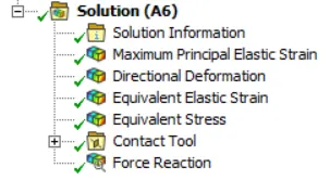
All the necessary output variable are selected such as von Mesis stress, stress intensity, equivalent strain etc.
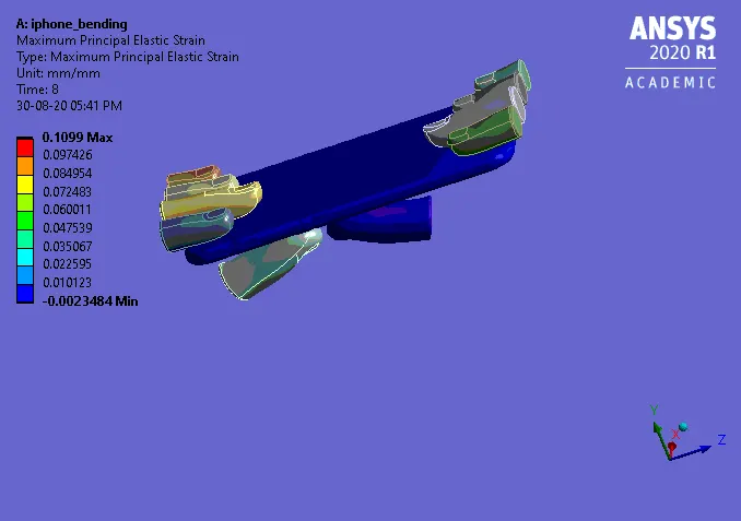
Case1
Directional Deformation (Y)
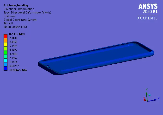
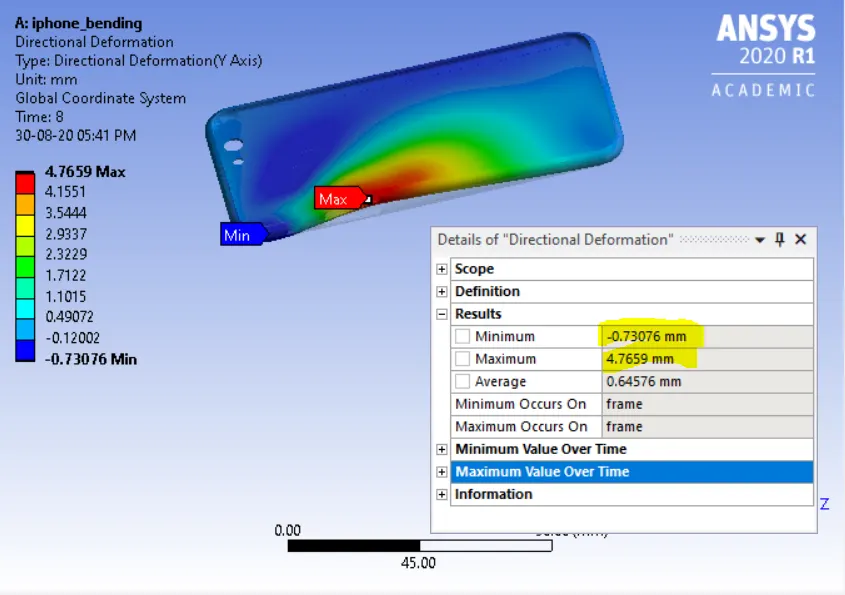
Equivalent stress
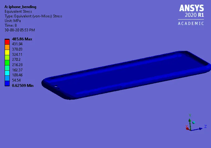
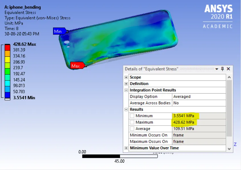
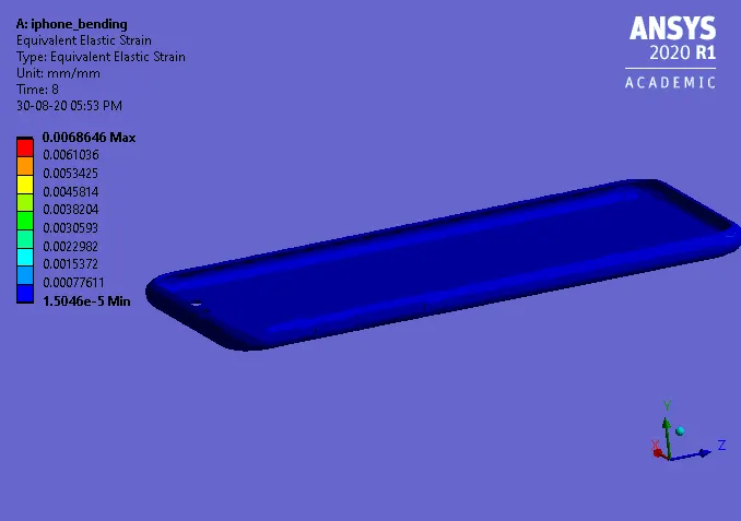
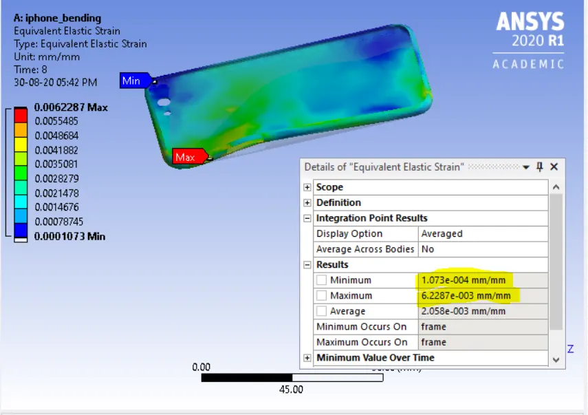
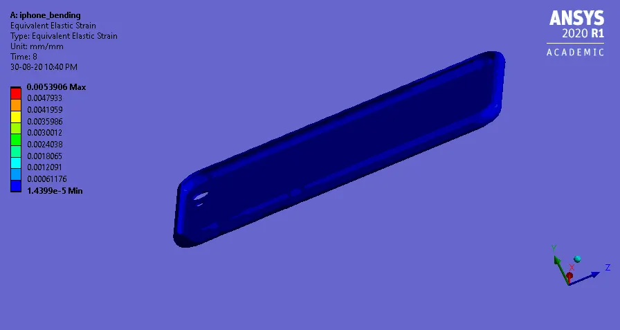
Equivalent strain
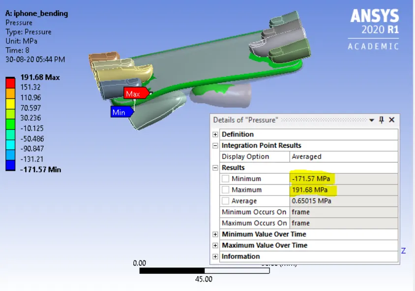
pressure
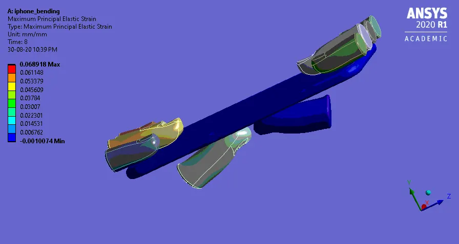
Case-2
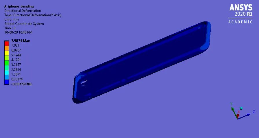
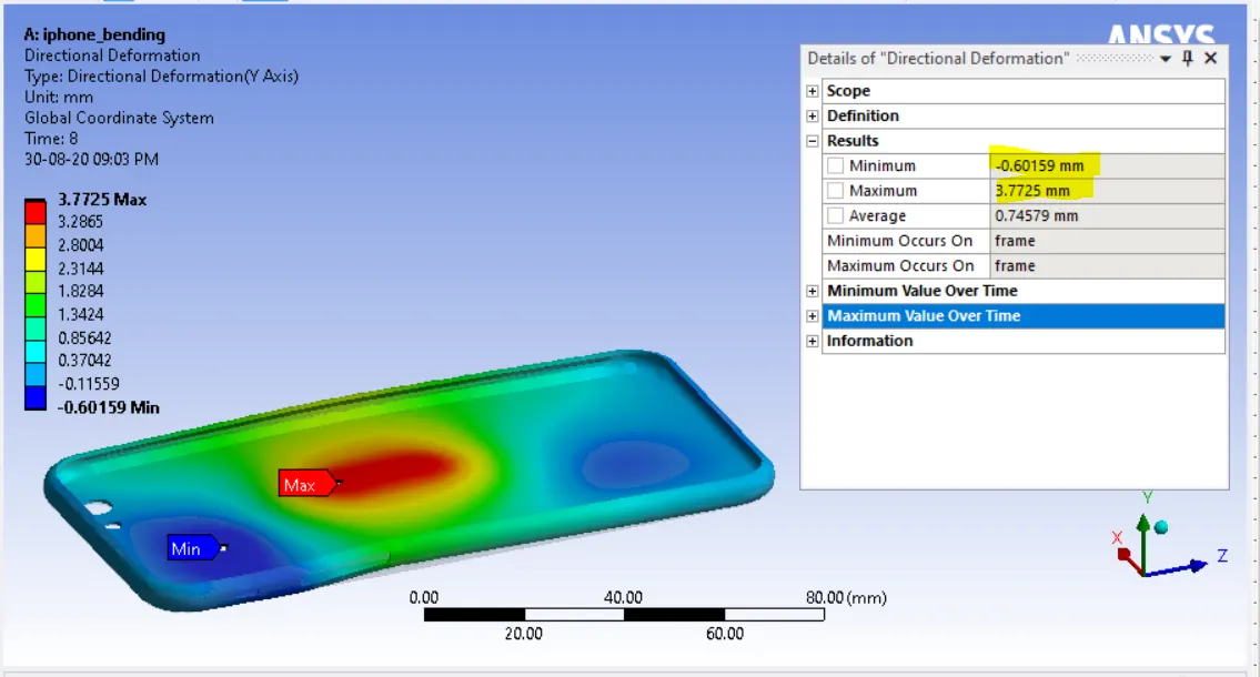
Directional deformation
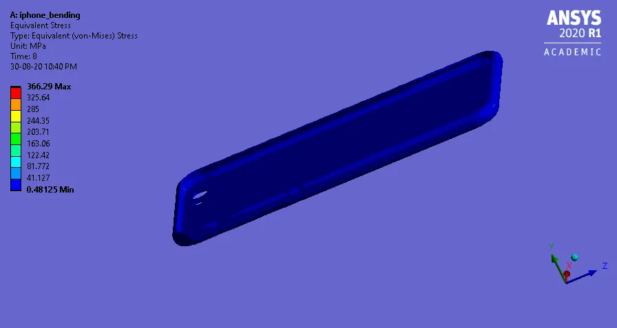
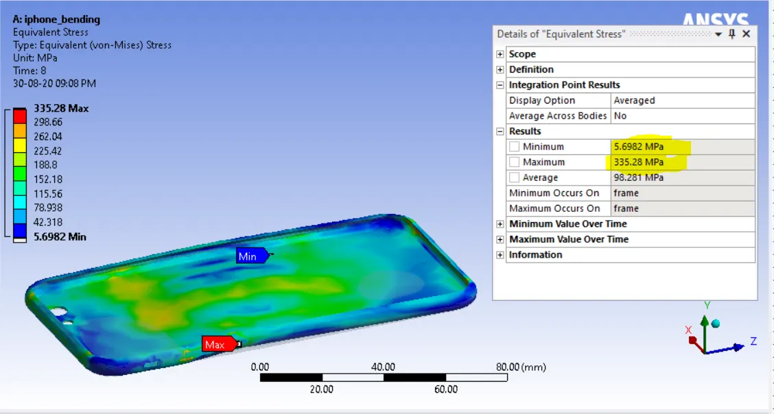
Equivalent stress
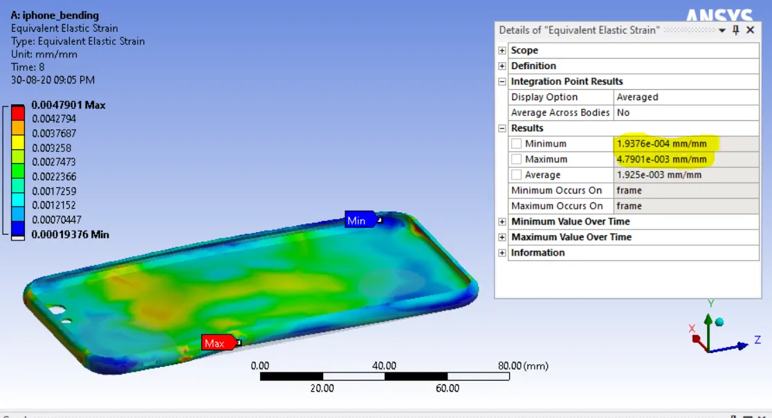
Equivalet strain
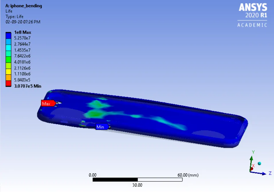
Life of aluminum alloy NL
Factor of safety for Aluminum alloy NL
Observations
| Deformations (mm) | stress (MPa) | strain (mm/mm) | |
| Case-1 | 4.7659 mm | 42862 Mpa | 6.2287e-003 (mm/mm) |
| Case-2 | 3.7725 mm | 33 528 Mpa | 4.7901e-003 (mm/mm) |
From the result obtained, it is found that , it is evident that the stress at the second case is reduced to more than half of the value of stress at the first case because of the uniform dirtributions of applied load at the middle of the iphone frame. Also the deformations productions produced at both the cases do not have much different between them .
The factor of the safety has increased in case 2 this indicate that when the Iphone is se to bending with applied load at the middle , the frame made up of aluminium alloy Nl material overcomes the failure limit than that of case2
Thus , case 2 shows a better result than case 1 as per the analysis