Week 9 Machining with Planer Challenge
Machining with Planer using Ansys
Objective: To Perform an explicit dynamic analysis of Machining operations with a planer cutting Tool
Case_1- cutting velocity of 20000 mm/s
Case_2- cutting velocity of 15000 mm/s
Simulation Process:
Create an explicit dynamics analysis and in engineering data select the material steel 1006 from explicit materials and structural steel
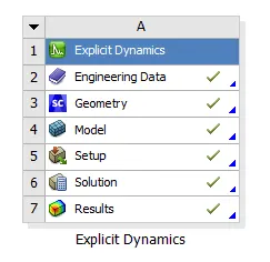
Case_1 – cutting velocity of 20000 mm/s
Input Geometry
Import the geometry and check in space claim for any irregularities
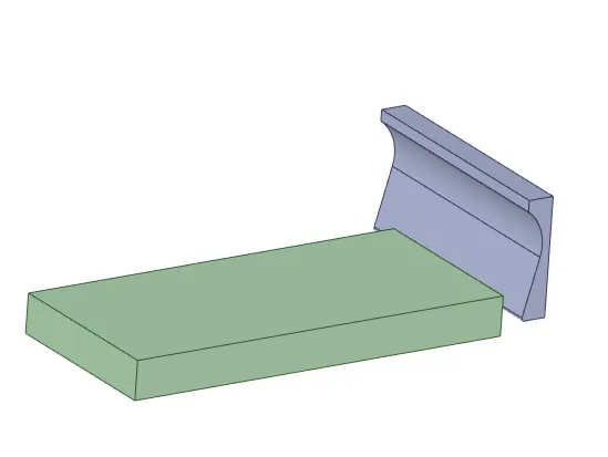
Then open Ansys mechanical and rename the component as Work piece and cutting Tool then assign the steel 1006 material to the work piece steel and structural steel material to the cutting tool and change the stiffness behaviour of the cutting tool to Rigid
Material:
The material used for the entire simulations was structural steel and steel 1006
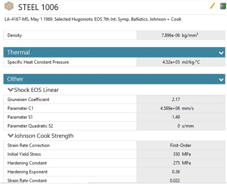
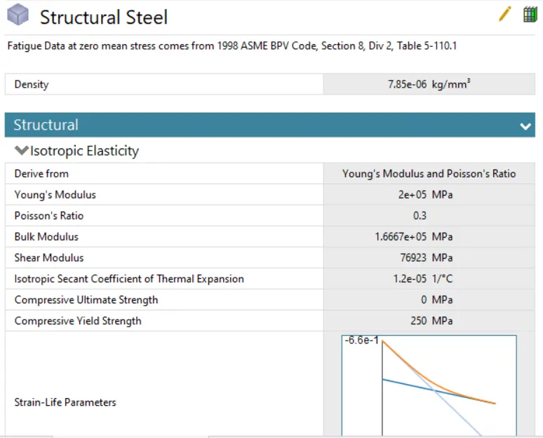
Mesh
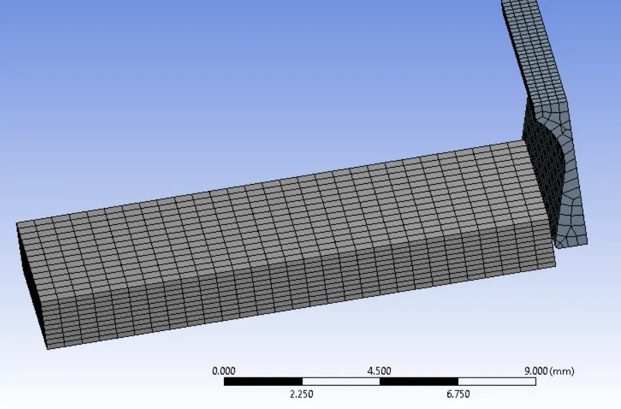
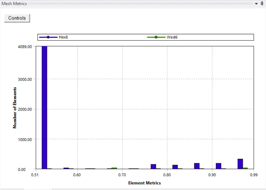
- The cutting tool is meshed by patch conforming method using Tetrahedron elements
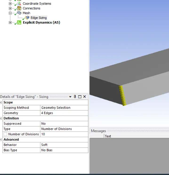
Edge Sizing – the work piece is meshed by defining 10 elements along its edge
Boundary conditions
- Fixed support- Work piece is fixed
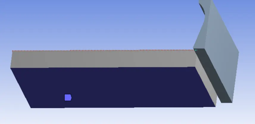
- Velocity- cutting tool provides the velocity of 20000 mm/s
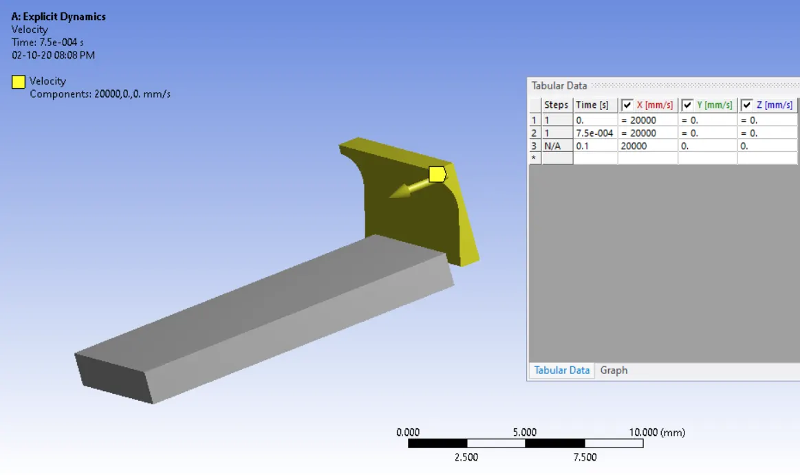
Analysis setting:
- Set end time as 7.5e-4, with maximum number of cycles as 1e+7, Maximum error set to 0.1
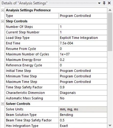
Solutions:
All the necessary output variable are selected such as von Mesis stress, stress intensity, equivalent strain etc.
Result – The analysis runs successfully and results obtained.
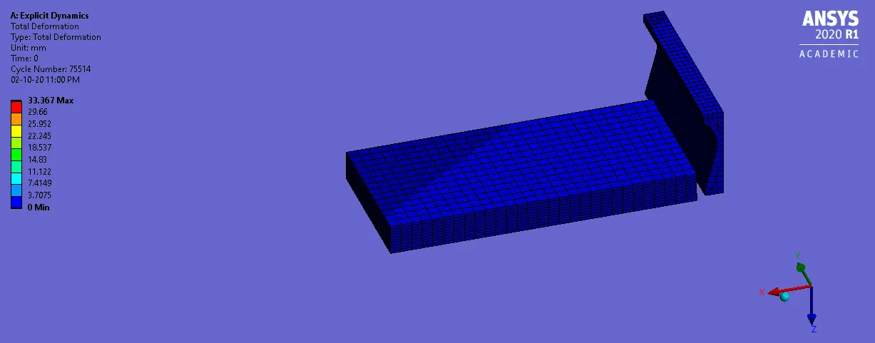
Total Deformations
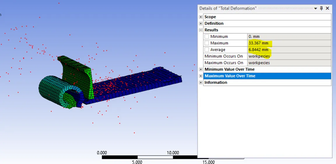
Equivalent strain
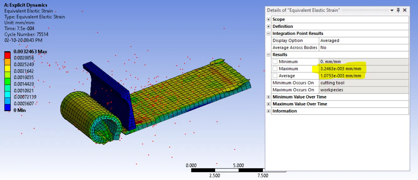
Equivalent stress
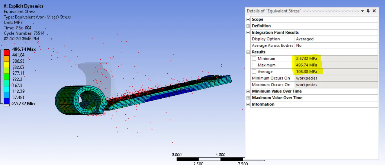
Temperature
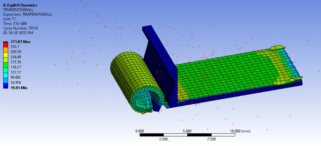
Case_2- cutting velocity of 15000mm/s
Velocity- Cutting tool provides the velocity of 15000mms/s
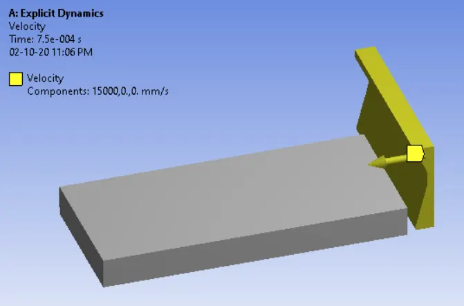
In Analysis setting- set end time as 7.5e-4, with maximum number of cycles as 1e+7, maximum error set to 0.14
Other setup same as case 1
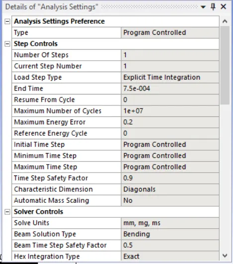
Run the simulations and results obtained
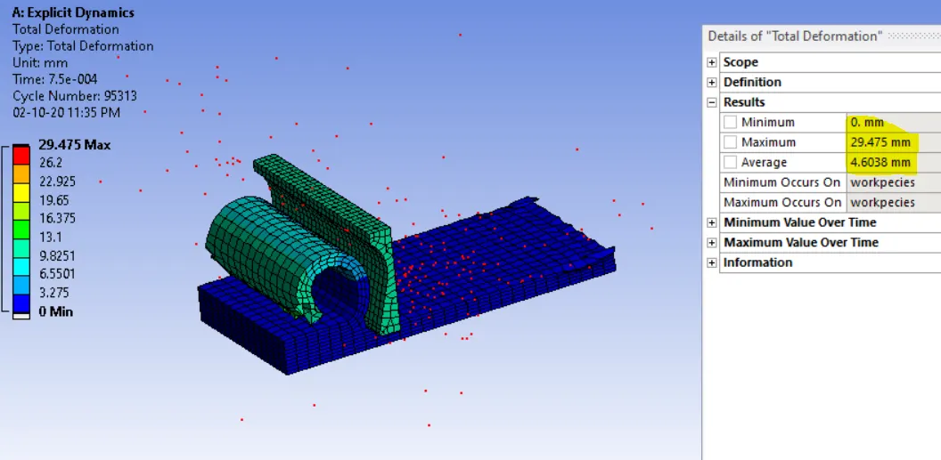
Result – The analysis runs successfully and results obtained.
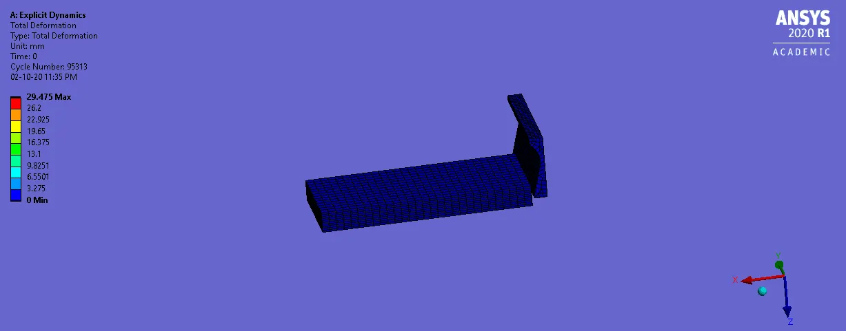
Total Deformations
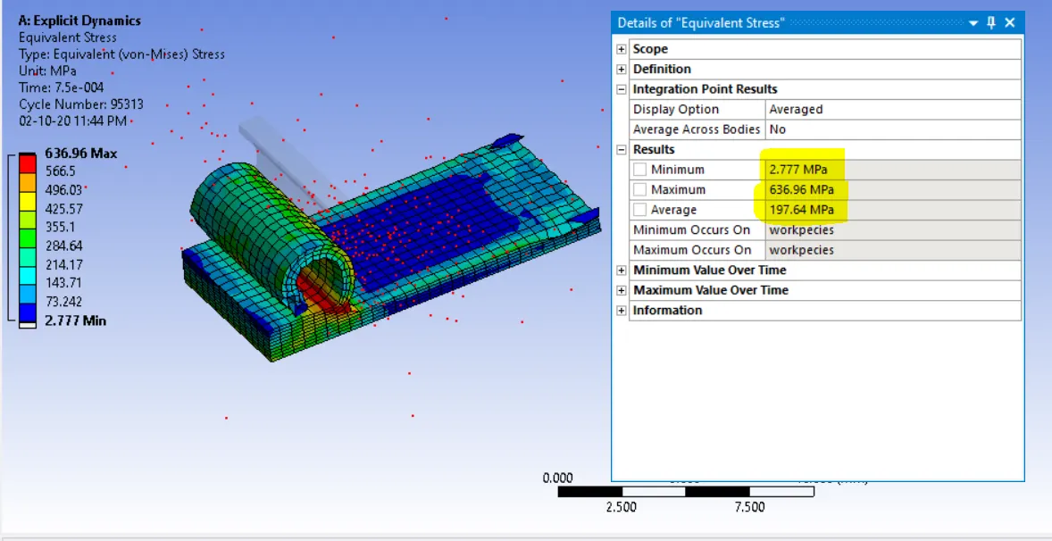
Equivalent stress
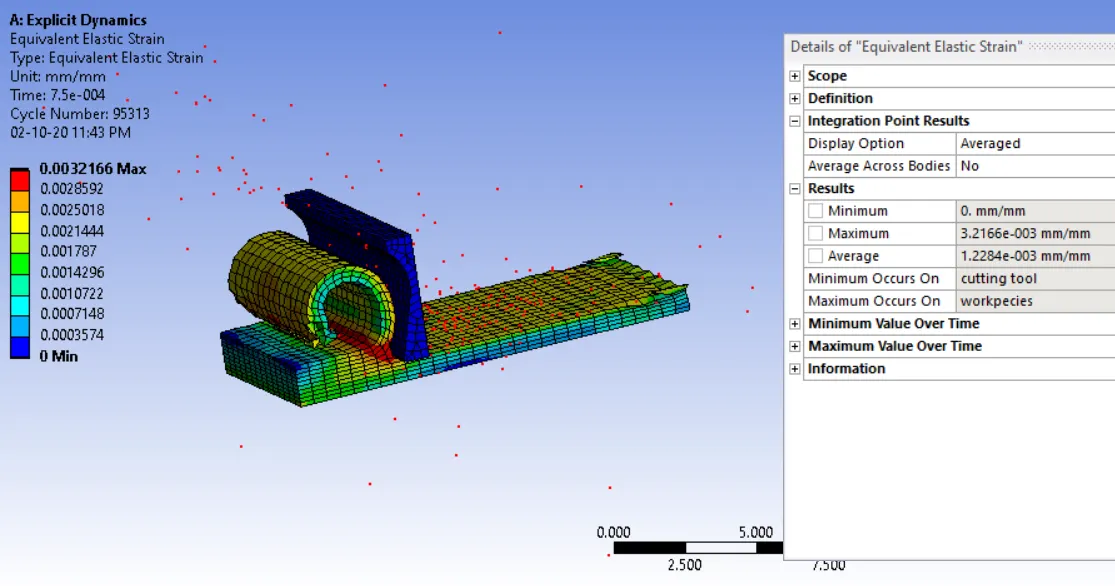
Equivalent strain
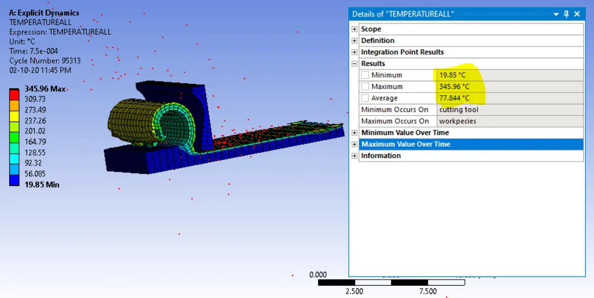
Temperature
Equivalent stress is lower in case 1 as the cutting tool has already removed the intended amount of material from the specimen due to high velocity.
The case 1 has higher temperature as compared to case 2 as it removes more material as compared to case 2
Run time is content in both cases; a reduction in the feed velocity reduces the amount of material removed from the work piece. This is evident from the total displacement of the cutting tool, which displaces 15mm in case 1 and 11.25mm in case 2
Both the simulations run successfully with the Maximum energy errors of 0.1 and 0.1 for case 1 and case 2 respectively