Week 8 Worm Gear Challenge
Transient Structural Analysis on a Worm Gear assembly using Ansys workbench
Objective: TO perform a transient structural analysis on a worm gear assembly
Simulation Process:
Create Transient structural analysis and in engineering data select the material structural steel
Input Geometry
Import the geometry and check in space claim for any irregularities
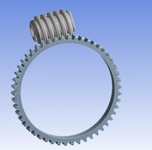
The Gear is cut into two half. One of the half of the gear is deleted in the model
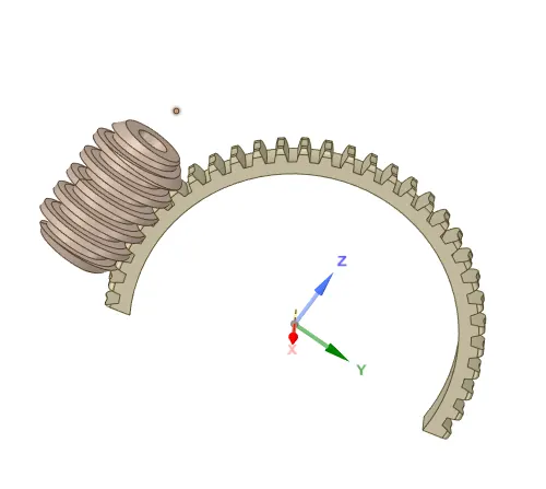
Then open Ansys mechanical and rename the geometry material
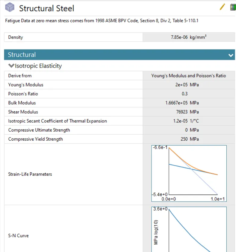
Material:
The material used for the entire simulations was structural steel
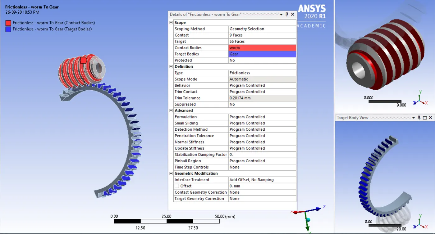
Contacts:
Frictional contact is defined between the worm and the gear. The contact formulation is done using Augmented Lagrange method and the interface treatment is selected as adjust to touch
Joints:
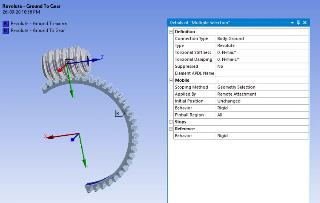
Revolute type joint are created for gear and worm with connection type as Body-Ground
Mesh
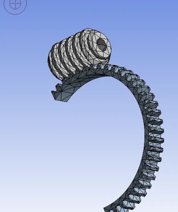
- The model is meshed with tetrahedral element with element size 4 mm
Boundary conditions
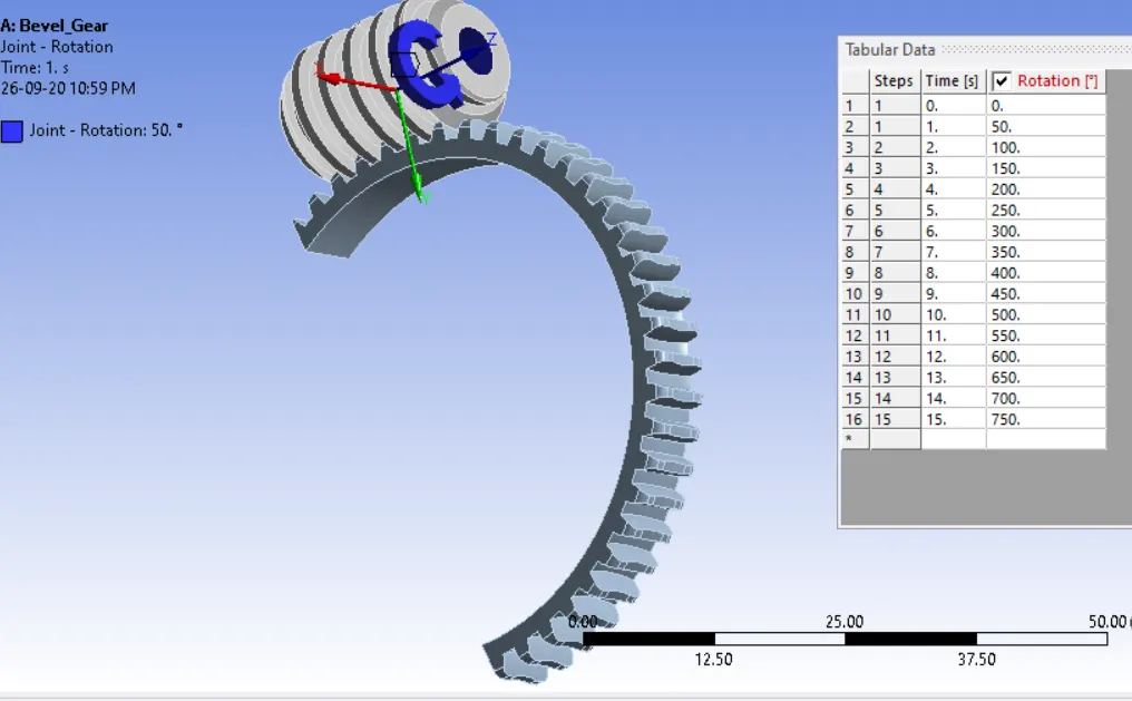
- Rotations joint load is defined for the worm with 50 time steps and 50 degree rotations per steps
Analysis setting:
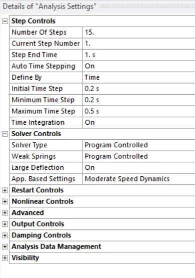
- The simulations run for 15 steps.
- In the first steps large deflections set to on and defined by time. Initial time set to 0.2s, Minimum time step set to 0.1s and maximum time steps to 0.5s. in output control set all output to yes
- The second steps to four steps large deflection set to on and defined by time. Carry over time set to on, Minimum time step set to 0.2s and Maximum time steps to 0.5s. in output control set all output to yes
Solutions:
All the necessary output variable are selected such as von Mesis stress, stress intensity, equivalent strain etc.
Result – The analysis runs successfully and results obtained.
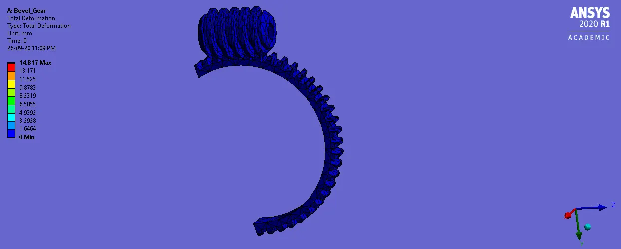
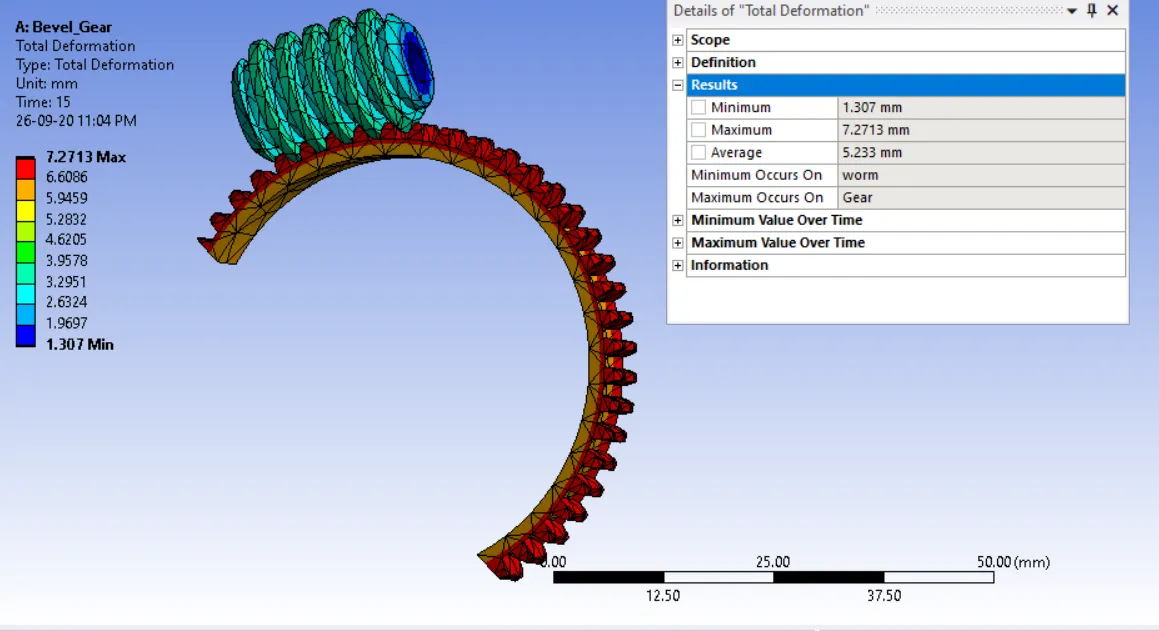
Total Deformations
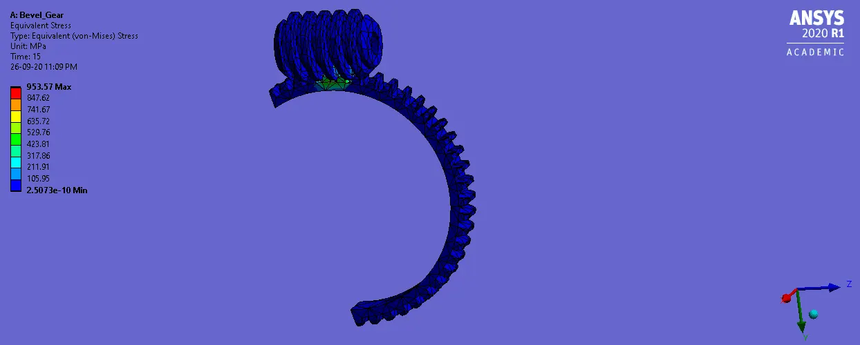
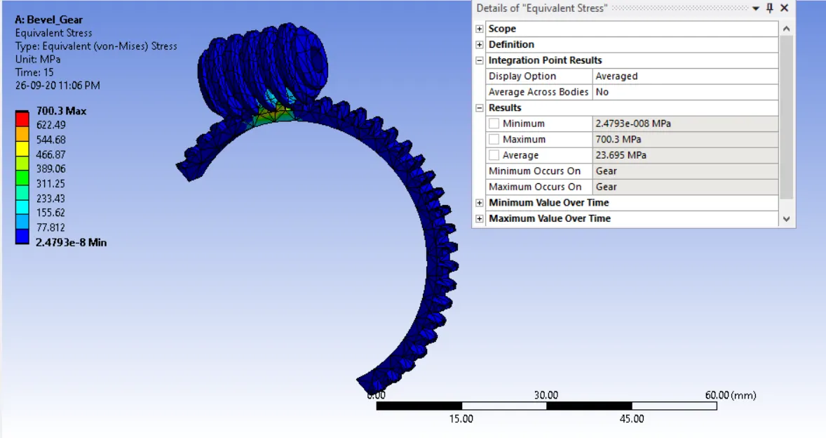
Equivalent stress
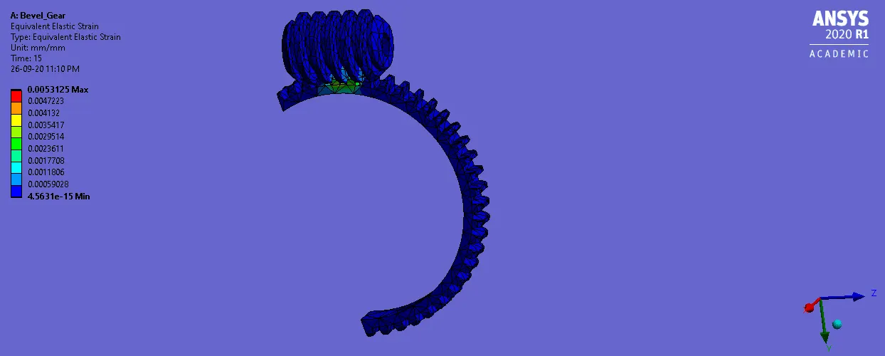
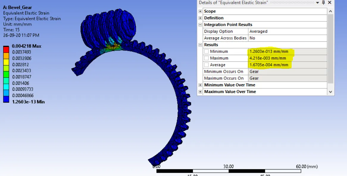
Equivalent strain
Conclusions:
Thus the worm gear assembly is simulated with transient structural analysis and the following results are obtained.
Max. Total deformation = 7.2717mm
Max. Equivalent Stress= 700.3 Mpa
Max .Equivalent Strain = 4.218e-003 mm/m