Week 9 Tension and Torsion test challenge
Tension Test and Torsion Test on a cylindrical specimen using Ansys
Objective: To perform the tension and torsion test on the specimen
Case_1- Tension test, displace one end of the specimen to 18mm while keeping the other fixed.
Case_2-Torsion Test, displace one end of the specimen to an angle 1200 degree while keeping the other fixed
Simulation Process:
Create Explicit Dynamics in Ansys workbench and in engineering data select the Material steel 1006 from explicit materials

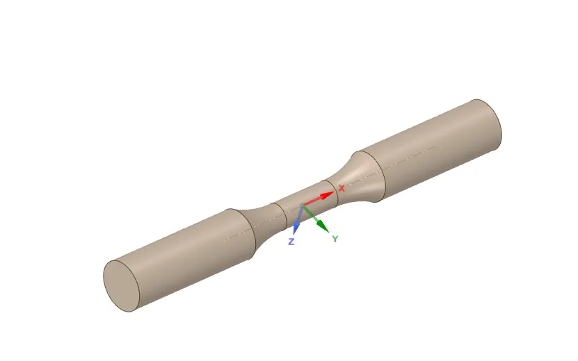
Input Geometry
Import the geometry and check in space claim for any irregularities
Then open Ansys mechanical and rename the geometry material
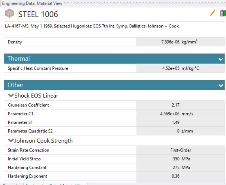
Material:
The material used for the entire simulations was steel 1006 from explicit material
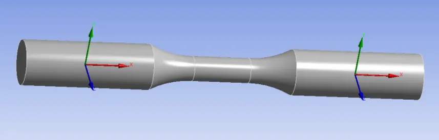
Co-ordinate System – For meshing, two additional Cartesian co-ordinated system are defined
Mesh
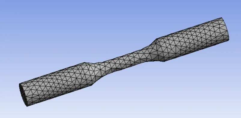
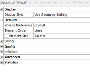
- The model is meshed by using Patch conforming Method and Tetrahedrons used
Face sizing- Face sizing options used. Type set to sphere of influence with sphere centre as the centre of the manually defined co-ordinate system and sphere radius of 22mm and sphere radius of 22m and element size of 3 mm
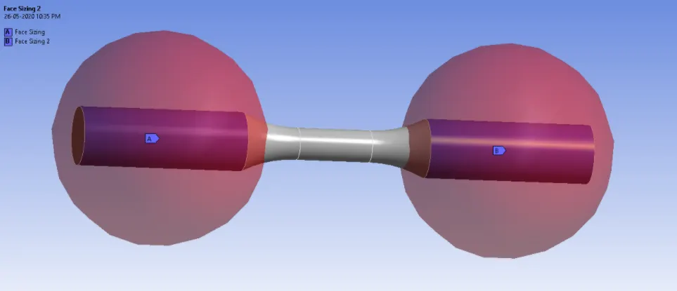
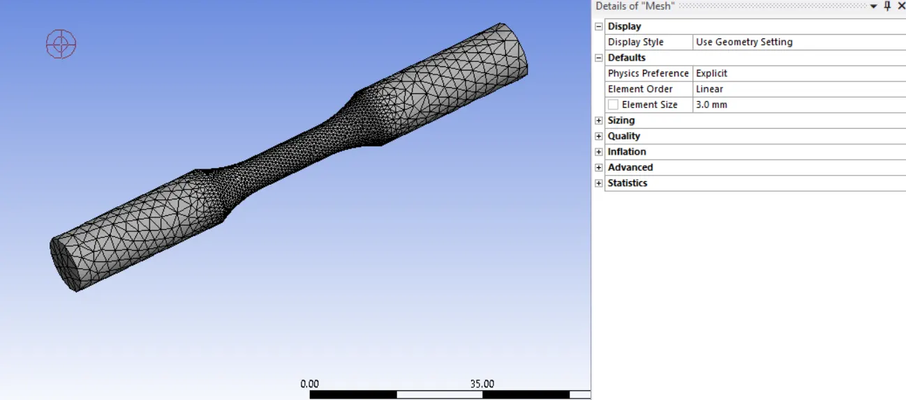
Final Mesh-
Boundary conditions
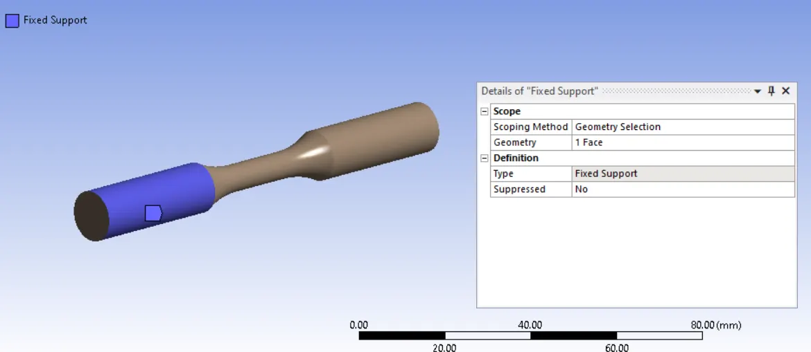
Fixed support- one end of the specimen is fixed
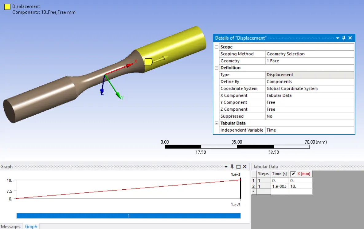
Displacement- displace other end of the specimen to 18mm
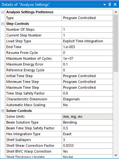
Analysis setting:
- Set end time as 1e-3, and all the setting set to default.
Solutions:
All the necessary output variable are selected such as von Mesis stress, stress intensity, equivalent strain etc.
Case_1- Tension test, displace one end of the specimen to 18mm while keeping the other fixed.
Result – The analysis runs successfully and results obtained.
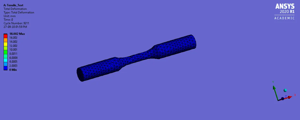
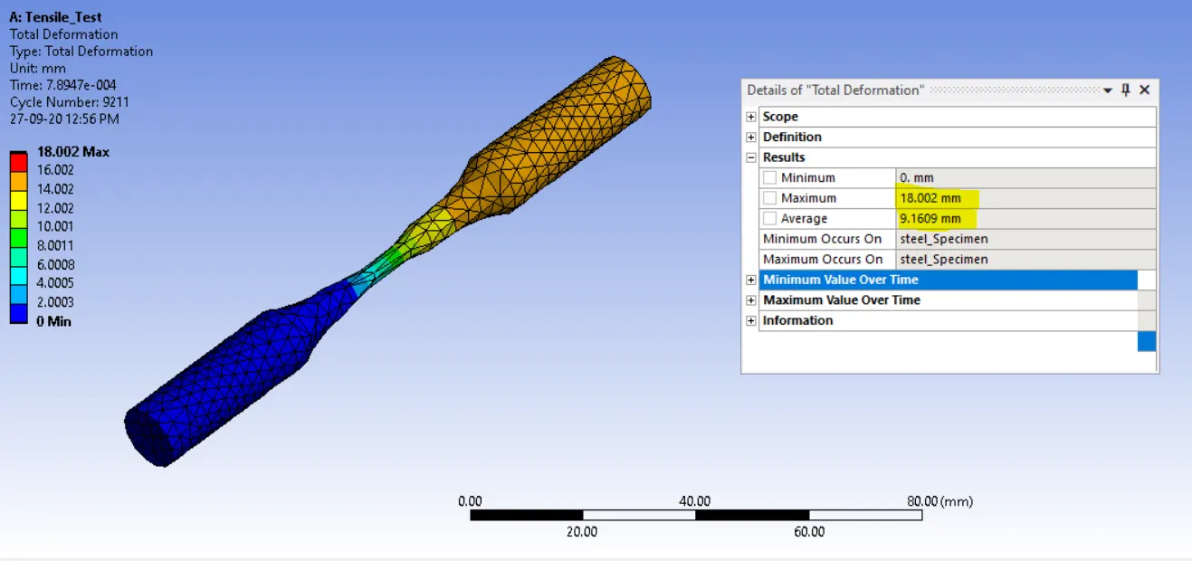
Total Deformations
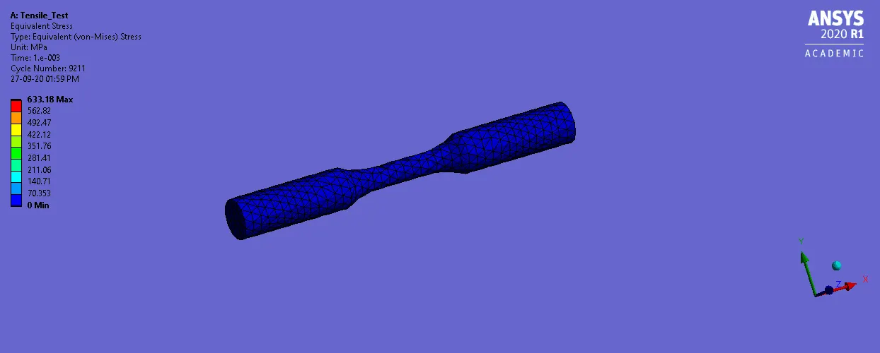
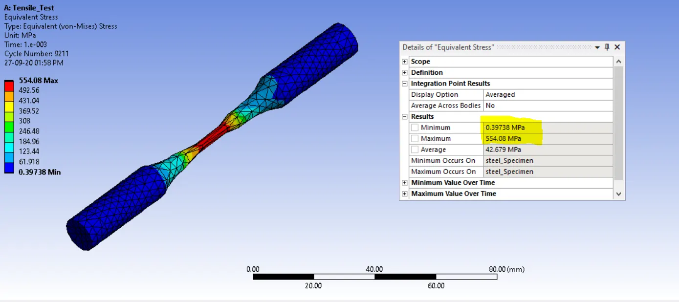
Equivalent stress
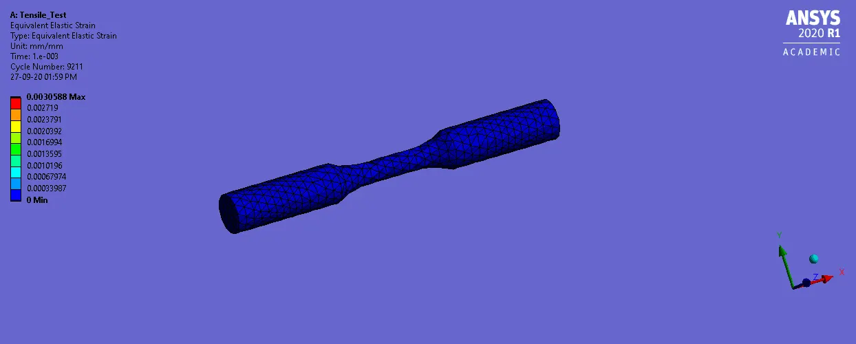
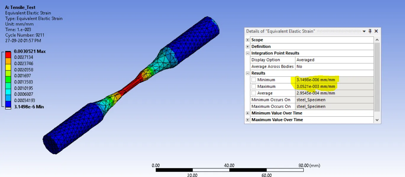
Equivalent strain
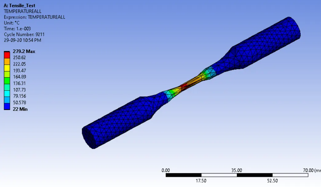
Temperature Max
Conclusions:
Max Equivalent Stress is developed in the center portion of the work piece, where neck formations occur.
Maximum Temperature is developed at the center portion.
The Maximum deformation of the work piece is 18.002 which matches the given displacement value
Case_2-Torsion Test, displace one end of the specimen to an angle 1200 degree while keeping the other fixed
Note- follow the same step, describe above but do change in boundary conditions and meshing
co-ordinate system - for meshing , two additional co-ordinate system are defined and one cylindrical defined
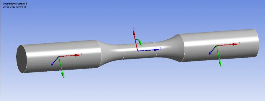
Face Sizing- type set to sphere of influence with sphere center as the center of the manually defined co-ordinate system and sphere radius of 8 mm and element size of 1mm
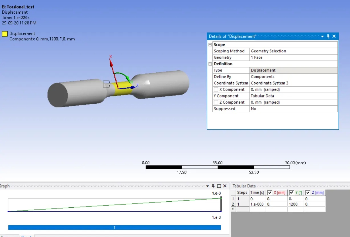
Boundary conditions
Fixed support- one end of the specimen is fixed
Displacement- Displace one end of the specimen to an angle of 1200 degree
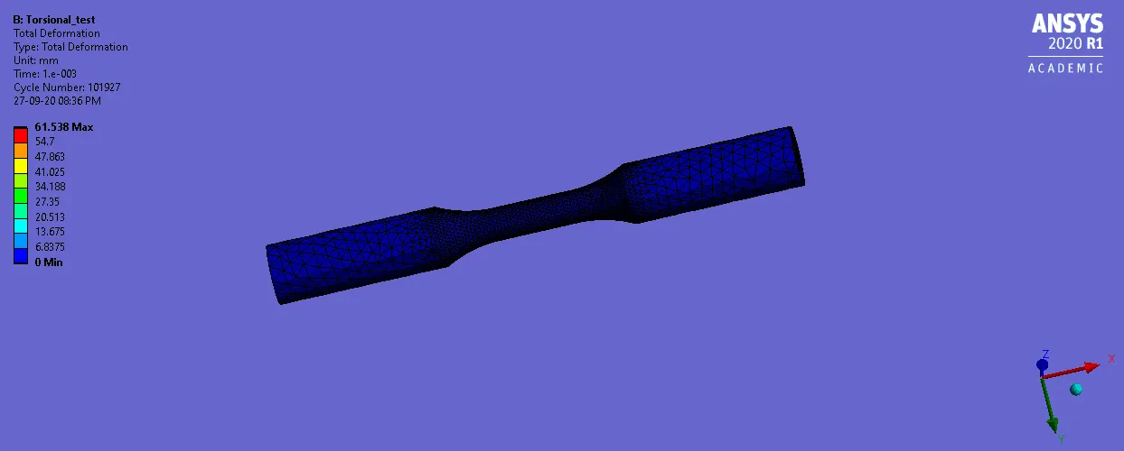
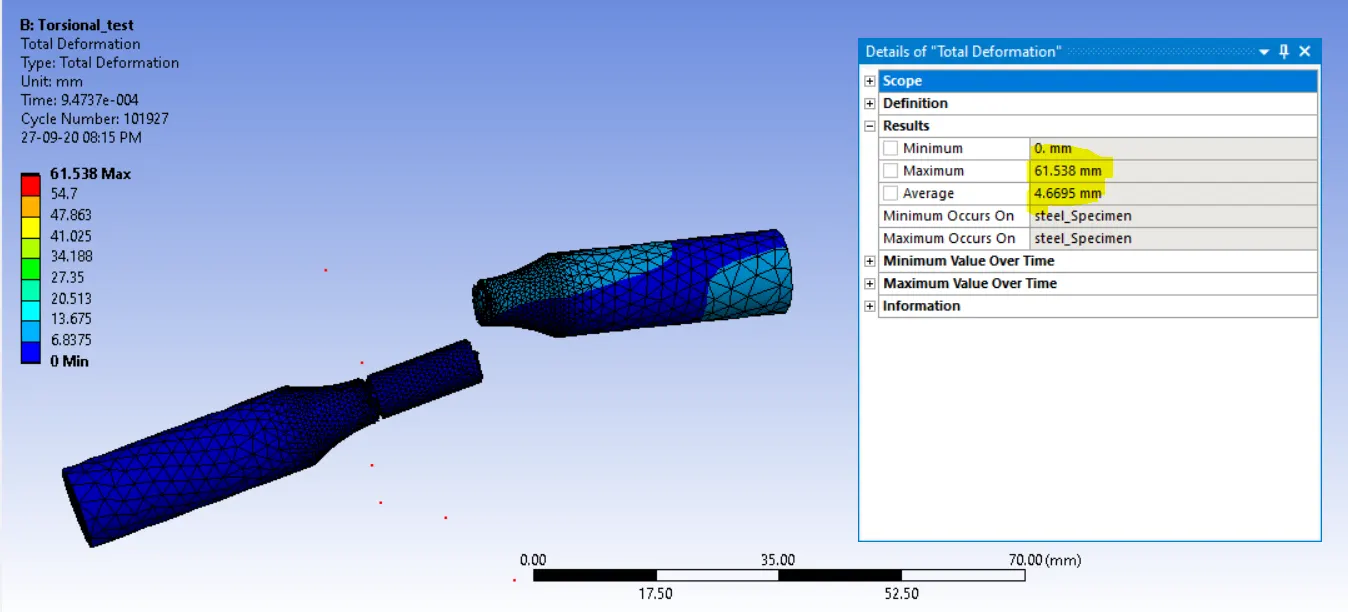
Max. Total deformation
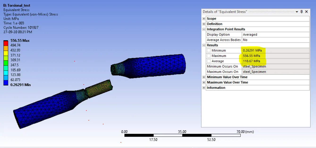
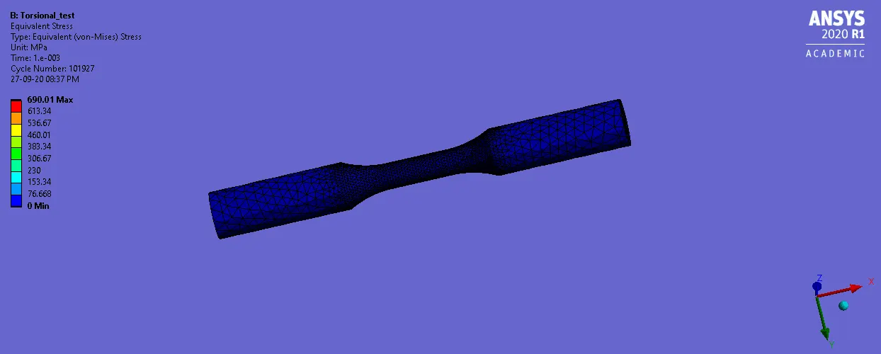
Max. Equivalent Stress
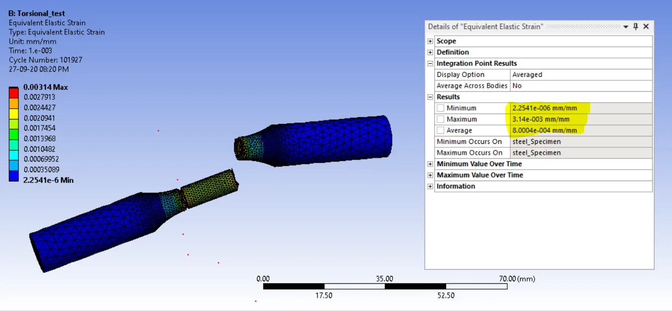
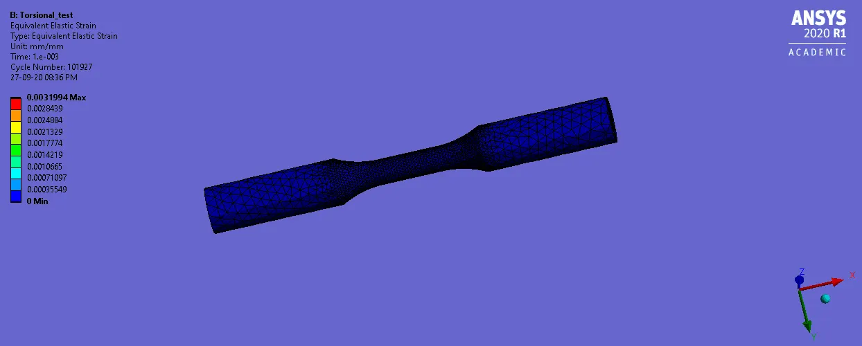
Max .Equivalent Strain
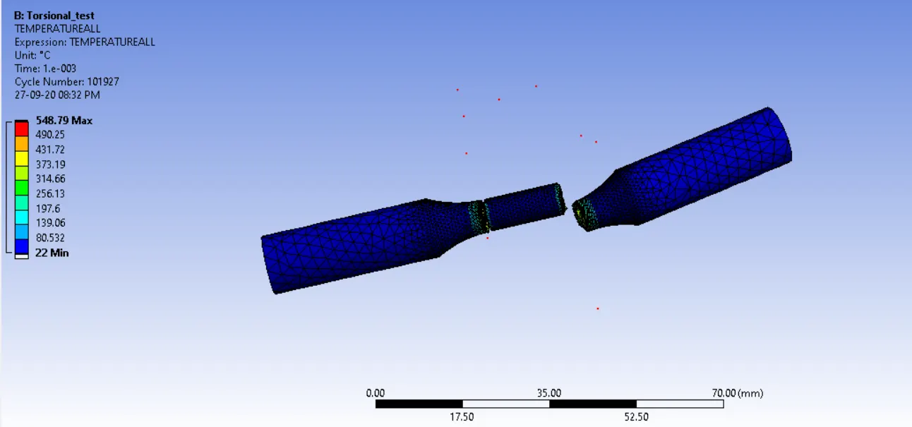
Temperature Max
Conclusions:
Max Equivalent stress is developed in the center portion of the work pieces.
Maximum Temperature is developed at the center portion