Radar Mast & Final Assembly of Yacht
Radar Mast

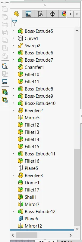
Modelling of yacht
Introduction:
In this project we are to learn the entire modeling of yacht tutorial on solid works and solid works visualize.
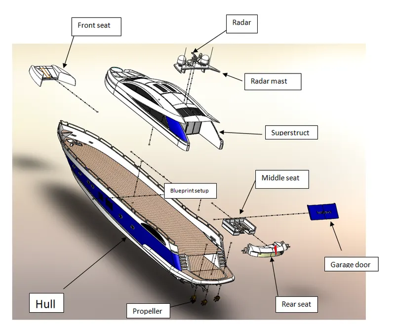
The different components of the yacht we deal with are:
- Propeller
- Radar
- Blueprint setup
- Hull
- Garage door
- Front seat
- Middle seat
- Rear seat
- Superstructure
- Radar mast
After designing the part components, we have worked upon the assembly and the photo rendering of the yacht which gives it a complete and realistic view.
Design approach:
Let we start with propeller and ending with rendering as shown in
below flow chart.
1. PROPELLER:
A propeller is a device with a rotating hub and radiating blades that are set at a pitch to form a helical spiral, that, when rotated, exerts linear thrust upon a working fluid, such as water or air. Propellers are used to pump fluid through a pipe or duct or to create thrust to propel a boat through water or an aircraft through the air. The blades are specially shaped so that their rotational motion through the fluid causes a pressure difference between the two surfaces of the blade by Bernoulli's principle which exerts a force on the fluid. Most marine propellers are screw propellers with helical blades rotating on a propeller shaft with an approximately horizontal axis.
In this modeling, a lot of features are used shown below.
- REVOLVE:
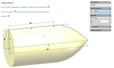
To create a revolve feature: Create a sketch that contains one or more profiles and a center line, line, or edge to use as the axis around which the feature revolves. Click one of the following revolve tools: Revolved Boss/Base (Features toolbar) or Insert > Boss/Base > Revolve.
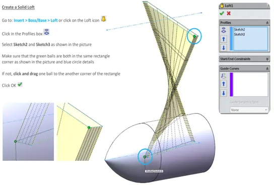
- LOFT:
The loft feature in SOLIDWORKS allows you generate complex geometry in a single feature. It does this by interpolating surfaces between various cross-sections of a model. These cross-sections can be sketches, faces, or edges. In the loft interface, these cross-sections are considered “Loft Profiles”.
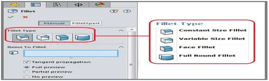
- FILLET:
Fillet/Round creates a rounded internal or external face on the part. You can fillet all edges of a face, selected sets of faces, selected edges, or edge loops.
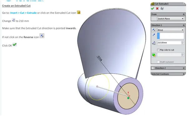
d.CUT EXTRUDE:
To create an extruded cut:
1) Sketch the profile for a cut.
2) Click Extruded Cut on the Features toolbar or select Insert, Cut, Extrude on the menu bar.
3) Under Direction 1, do the following: · Select an End Condition. Examine the preview and if necessary, click Reverse Direction to extrude in the opposite direction.
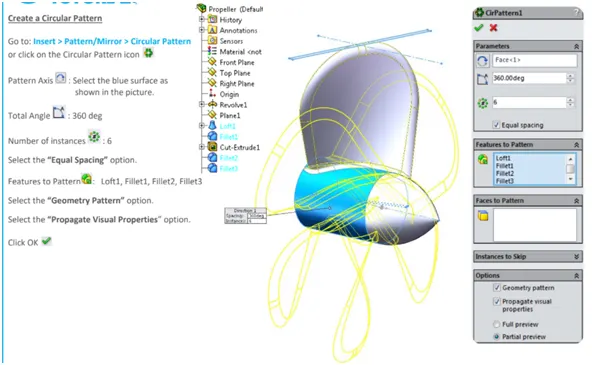
- CIRCULAR PATTERN:
Use circular patterns to create multiple instances of one or more features that you can space uniformly around an axis.
To create a circular pattern:
- Create one or more features to replicate.
- Click Circular Pattern (Features toolbar) or Insert > Pattern/Mirror > Circular Pattern.
- Set the PropertyManager options.
- Click ok.
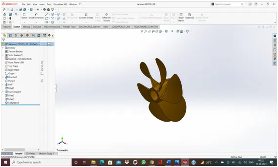
MODELLING OF PROPELLER:
2. RADAR:
It does so by detecting other ships and land obstacles, to give bearing and distance for collision avoidance and navigation while on water. A marine radar device acts as a major navigation aid for boaters. It helps in detecting boats, birds, landmasses, and weather systems - even if the visibility is less than usual.
In this modeling boss/base extrude, cut extrude, fillet, mirror, sketch pattern, a split line, etc.
- Boss extrude:
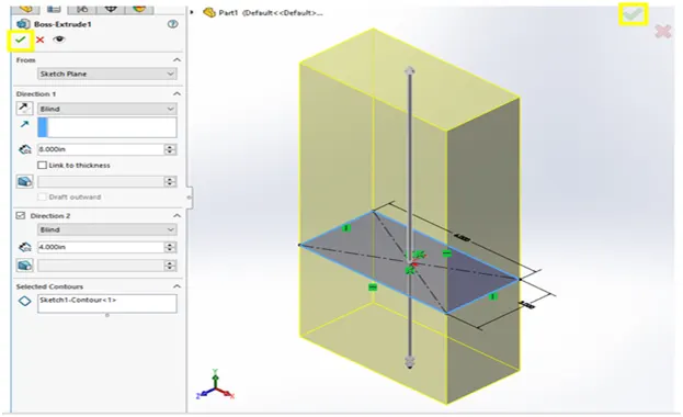
Extrude PropertyManager
- Create a sketch.
- Click one of the extrude tools: Extruded Boss/Base. on the Features toolbar, or click Insert > Boss/Base > Extrude. Extruded Cut. on the Features toolbar, or click Insert > Cut > Extrude. Extruded Surface. on the Surfaces toolbar, or click Insert > Surface > Extrude
- Mirror:
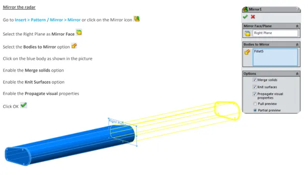
To mirror a feature: Do one of the following: In a part, click Mirror (Features toolbar) or Insert > Pattern/Mirror > Mirror. In an assembly, click Assembly Features (Assembly tab on the CommandManager) and click Mirror or click Insert > Assembly Feature > Mirror.
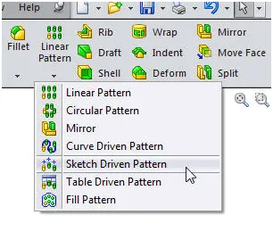
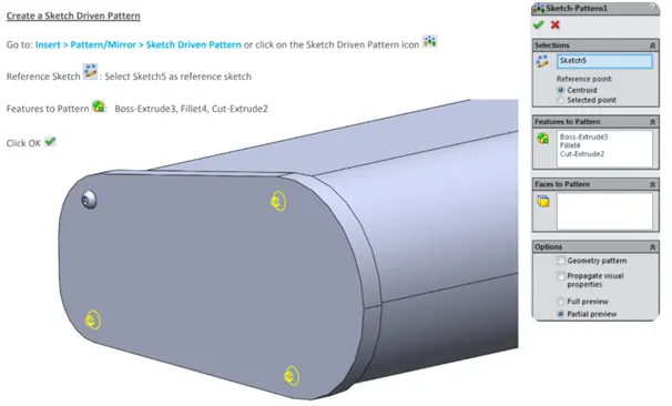
- sketch driven pattern:
Solidworks Pattern a Sketch
To build a sketch driven pattern:
- Open a sketch on the face of a part.
- Create a seed feature on the model.
- Click Point or Tools > Sketch Entity >Point, and add multiple sketch points to represent the pattern you want to create, based on the seed feature.
- Close the sketch.
- split line:
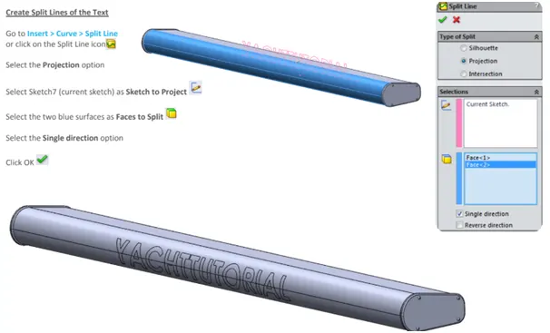
Using the split lines feature, the sketch lines are projected onto the selected faces and divide the faces into multiple regions as defined by the sketch. Once the split line is created, these selected regions can have a different appearance than the other regions, and function as a separate faces.
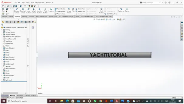
Modeling of radar:
3. blueprints setup:
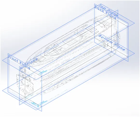
How to setting up blueprints in Solid Works?
- So, Let's Start the tutorial with New Part.
- start a sketch on the front plane by right click in the front plane Nd click the sketch icon.
- click in TOOLS after that click on Sketch Tools and after that click on sketch Picture.
4. HULL:
The hull of a ship is the most notable structural entity of the ship. To define the hull, it can be said that it is the watertight enclosure of the ship, which protects the cargo, machinery, and accommodation spaces of the ship from weather, flooding, and structural damage.
In this modeling, a lot of features are used.
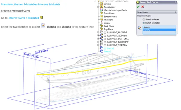
- project curve:
To project a curve: Click Project Curve on the Curves toolbar, or Insert > Curve > Projected. Use this selection to project a sketched curve onto a model face. Under Sketch to Project,select the curve in the graphics area or from the flyout FeatureManager design tree.
- surface loft:
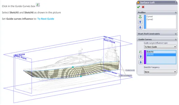
To create a lofted surface:
- Create a plane for each profile section of the loft. The planes do not need to be parallel.
- Sketch the section profiles on the planes. ...
- If necessary, create guide curves. ...
- Click Lofted Surface (Surfaces toolbar) or Insert > Surface > Loft.
- Set the PropertyManager options. ...
- Click OK.
- surface trim:
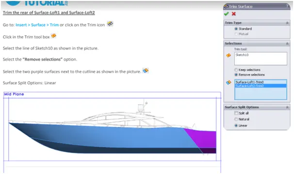
To trim a surface:
- Create two or more surfaces that intersect at one or more points, or create a surface that intersects with a plane or has a sketch on its face.
- Click Trim Surface on the Surfaces toolbar, or click Insert > Surface > Trim.
- In the PropertyManager, under Trim Type, select a type:
- Trims surfaces using surfaces, sketch entities, curves, planes, and so on.
- Trims multiples surfaces using the surfaces themselves.
- Under Selections, choose from these options:
- Trim tool (available with Standard selected under Trim Type). Select a surface, sketch entity, curve, or plane in the graphics area as the tool that trims other surfaces.
- Surfaces (available with Mutual selected under Trim Type). Select multiple surfaces in the graphics area for Trimming Surfaces to use to trim themselves.
- Select a trim action:
- Keep selections. Retains the surfaces listed under Pieces to Keep. Intersecting surfaces not listed under Pieces to Keep are discarded.
- Remove selections. Discard the surfaces listed under Pieces to Remove. Intersecting surfaces not listed under Pieces to Remove are retained.
- Select surfaces in Pieces to Keep or in Pieces to Remove, based on the trim action.
- If you selected Mutual Trim, Preview options are available. Select one of the following:
|
Show included surfaces |
Displays the regions that you are including as surfaces. All other surfaces are hidden. |
|
|
Show excluded surfaces |
Displays the surfaces that you are excluding as transparent. All other surfaces are hidden. |
|
|
Show both included and excluded surfaces |
Displays both included and excluded surfaces. Excluded surfaces appear transparent. |
- Under Surface Split Options, select an item:
- Boundaries extend tangent from the ends of the Trim tool.
- Boundaries extend from the Trim tool endpoints to the nearest edge.
- Optionally, select Split All.
Example: Trim Surface - Surface Split Options
- Click
- surface extrude:
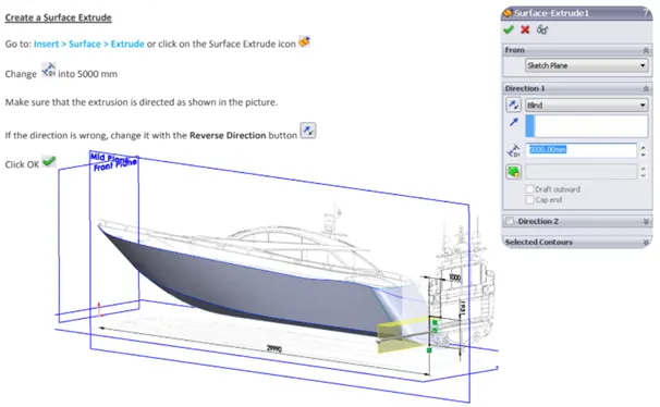
Extruding Surfaces from a 2D or 3D Face
- Click Insert > Surface > Extrude.
- Select a face: ...
- Select other faces to define the extrude as required. ...
- Select the end condition.
- For 3D faces, select a plane, edge, 2D face, or sketch line to define the direction of extrusion.
- shell:
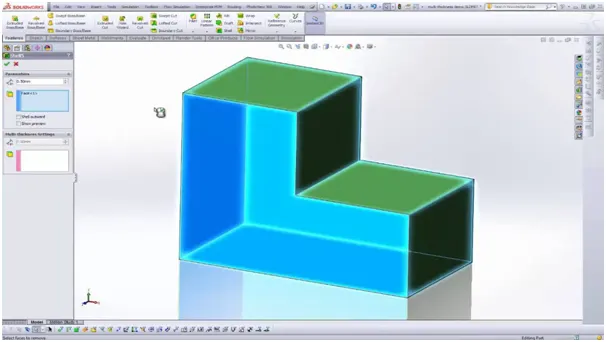
The shell tool hollows out a part, leaves open the faces you select, and creates thin-walled features on the remaining faces. If you do not select any face on the model, you can shell a solid part, creating a closed, hollow model. You can also shell a model using multiple thicknesses.
- chamfer:
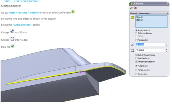
The chamfer tool creates a bevelled feature on selected edges, faces, or a vertex.
To create a chamfer:
- Click Chamfer (Features toolbar) or Insert > Features > Chamfer.
- Under Chamfer Parameters, select an item and set parameters. ...
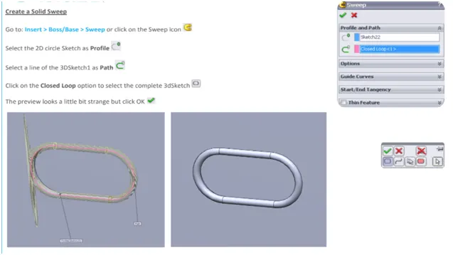
- sweep:
To create a sweep:
- Sketch a closed, non-intersecting profile on a plane or a face. If you use guide curves: ...
- Create the path for the profile to follow. Use a sketch, existing model edges, or curves. ...
- Click one of the following: ...
- In the PropertyManager: ...
- Set the other PropertyManager options. Click Ok.
- dome:
Click Dome on the Features toolbar, or click Insert > Features > Dome. Select one or more planar or non-planar faces. Set a value for the distance by which the dome expands. Click to create a concave dome (default is convex).
- LINEAR PATTERN:
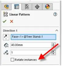
To create a linear sketch pattern:
- In an open sketch, click Linear Sketch Pattern. (Sketch toolbar) or Tools > Sketch Tools > Linear Pattern.
- In the PropertyManager, under Entities to Pattern, select the sketch entities to pattern.
- Set values for Direction 1 (X-axis). ...
- Repeat for Direction 2 (Y-axis). ...
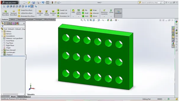
You can use linear patterns to create multiple instances of one or more features that you can space uniformly along one or two linear paths. Seed feature. Linear pattern - two directions. Linear pattern - one direction.
- COMBINE:
To add bodies together:
- Click Combine. (Features toolbar) or Insert > Features > Combine.
- In the PropertyManager, under Operation Type, select Add.
- For Bodies to Combine, select the bodies to combine. You can select bodies in the graphics area or the Solid Bodies. ...
- Click Show Preview to preview the feature.
- helix/spiral:
The diameter of the circle controls the starting diameter of the helix or spiral. Click Helix and Spiral (Curves toolbar) or Insert > Curve > Helix/Spiral. Set values in the Helix/Spiral PropertyManager. Click.
- move/copy/delete the body:
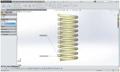
To move, copy, rotate, or mate a solid or surface body: Click Move/Copy Bodies (Features toolbar) or Insert > Features > Move/Copy. Specify parameters to move, copy, or rotate bodies. Apply mates between bodies.
Click Delete/Keep Body on the Features toolbar, or click Insert > Features > Delete/Keep Body. In the PropertyManager, select Delete Bodies or Keep Bodies. For Bodies to keep or Bodies to delete, select bodies in the graphics area or from the Solid Bodies folder for Solid/Surface Bodies to Delete/Keep. Click OK.
To move, copy, rotate, or mate a solid or surface body: Click Move/Copy Bodies (Features toolbar) or Insert > Features > Move/Copy. Specify parameters to move, copy, or rotate bodies. Apply mates between bodies.
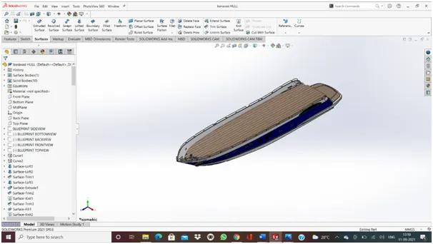
Modeling of hull:
5. garage door:
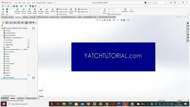
A garage door is a large door on a garage that opens either manually or by an electric motor (a garage door opener). Garage doors are frequently large enough to accommodate automobiles and other vehicles. Small garage doors may be made in a single panel that tilts up and back across the garage ceiling.
In this modeling, the tools and features are used as same as before models there are no new features here.
Modelling of garage door:
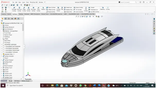
6.superstructure:
In the last modeling of the hull, I covered a lot of tools and features are used and showed how to use them and the remaining are shown in this modeling of the superstructure and next models.
a.surface sweep:
If you are using guide curves, create coincidently or pierce relations between the guide curves and the profile. Click Swept Surface (Surfaces toolbar) or Insert > Surface > Sweep. Set the PropertyManager options. Click OK.
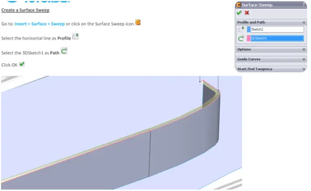
Sweep surfaces are surfaces that are generated from a section curve positioned along a path. ... Parallel Sweep is defined as a section curve moving along a guide path while maintaining the section curve to be parallel to the guide path.
b.surface knit:
Use the Knit Surface tool to combine two or more faces and surfaces into one.
Note the following about knit surfaces:
- Edges of the surfaces must be adjacent and not overlapping.
- Surfaces do not need to be on the same plane.
- Select the entire surface body, or select one or more adjacent surface bodies.
- Knit surfaces absorb the surface bodies you used to create them.
- Create a solid body when the knit surfaces form a closed volume or leave as a surface body.
- Select Merge entities to merge faces with the same underlying geometry.
- Select Gap Control to view the gaps or modify the knitting tolerance.
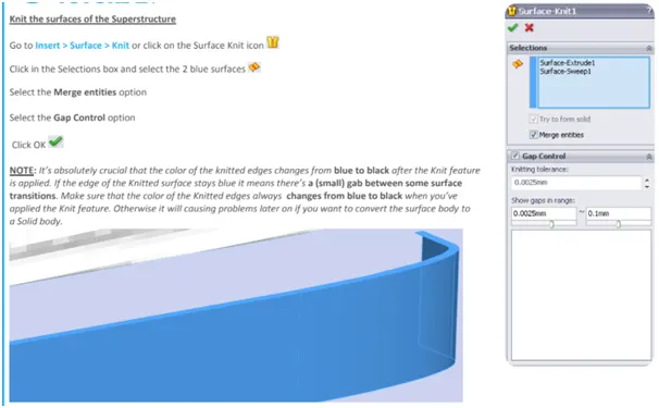
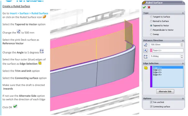
c.ruled surface:
To create a ruled surface: Click Ruled Surface on the mold Tools toolbar, or click Insert >molds> Ruled Surface. The ruled surface is tangent to the surfaces that share an edge. A ruled surface is normal to the surfaces that share an edge.
d.surface fill:
To create a filled surface, click Filled Surface on the Surfaces toolbar, or click Insert > Surface > Fill, set the PropertyManager options, and click OK. Set the PropertyManageroptions based on the type of filled surface you want to create
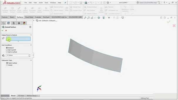
e.surface extend:
To extend a surface:
- Click Extended Surface (Surfaces toolbar) or Insert > Surface > Extend.
- In the Property Manager: Under Edges/Faces to Extend, select one or more edges or faces in the graphics area for Selected Face/Edges. For edges, the surface extends along the plane of the edge.
Modelling of superstructure:
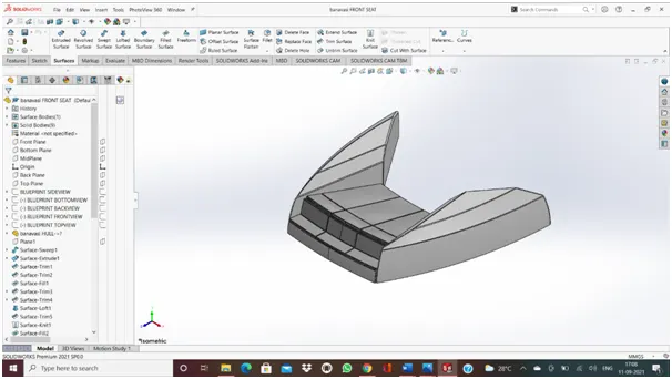
7. front seat:
In this modeling already use the tools and feature in the last model.
Modeling of front seat:
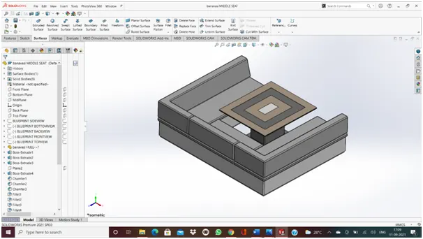
8. middle seat:
Modeling of middle seat:
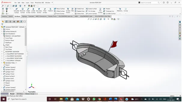
9. rear seat:
Modeling of rear seat:
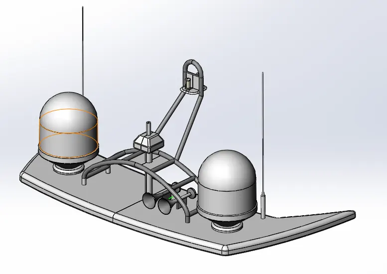
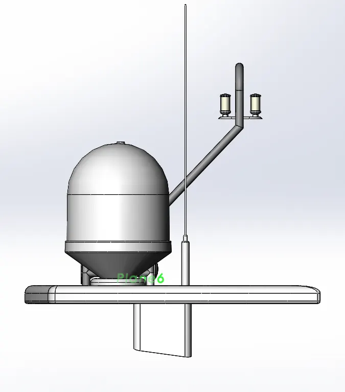
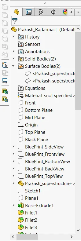
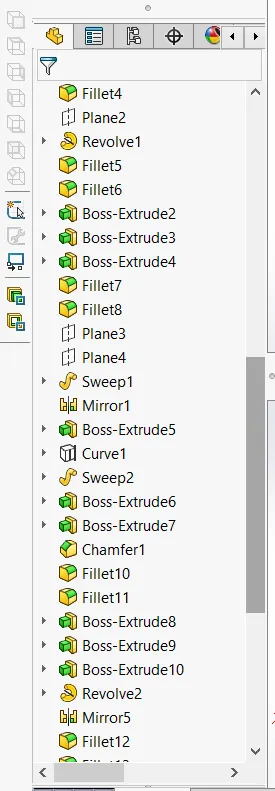
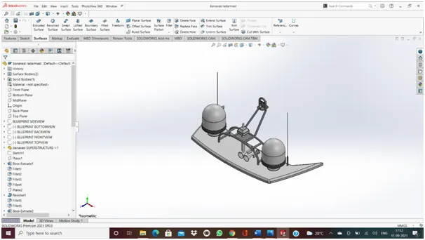
10. radar mast:
modelling of radarmast:
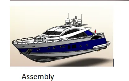
Assembly of yacht tutorial:
Front view of the yacht:
Side view of the yacht:
Top view of the yacht:
Isometric view of the yacht:
Back view of the yacht:
RENDERING:
Photo View 360 is a SOLIDWORKS add-in that produces photo-realistic renderings of SOLIDWORKS models. The rendered image incorporates the appearances, lighting, scene, and decals included with the model. Photo View 360 is available with SOLIDWORKS Professional or SOLIDWORKS Premium.
- With a model open, click Tools > Add-In and add in Photo View 360.
- Start a preview in the graphics area or open the Preview window to see how changes you make to the model affect the rendering.
- Edit appearances, the scene, and decals.
- Edit lights.
By default, lighting is off in Photo View. With lights off, you can use the realistic lighting provided by scenes, which is usually sufficient for rendering. You typically need additional lighting in Photo View to illuminate occluded spaces in the model.
- Edit PhotoView Options.
- When you are ready, perform a final render either now (PhotoView > Final Render) or later (PhotoView > Schedule Render).
If annotations or dimensions are visible in your model, a dialog box appears with options to include the dimensions and annotations or render without them.
If you have not added a camera or turned-on perspective view, which provides more realistic, higher-quality renderings, a dialog box appears. You can turn on a camera or perspective view from the dialog box or continue without them.
- Make detailed adjustments in the Final Render Window.
RENDERED IMAGES:
1.
2.
3.
4.
5.
6.
CONCLUSION:
All the parts of the yacht are modeled and assembled together successfully using solid works
We have used a lot of HDR environments, appearances, scenes, and finally rendered also.