DESIGN & ANALYSIS OF GLASS FIBRE FOR FORKLIFT ARM
DESIGN & ANALYSIS OF GLASS FIBRE FOR FORKLIFT ARM
INTRODUCTION
Because of the varieties, different shapes, different packaging of the goods, loading and unloading has always been a heavy process during transportations. Forklifts were naturally inverted and became the solutions to this problem; they save time and space. If cargos are being organized properly, the use of forklifts with the right attachments would be the best way to load and unload, which would make the whole process less time consuming and less labor intensive. In additions, forklifts optimize the use of storage space by eliminating the need for many people to handle the loading and unloading operations and enabling the stack-up of good
Objective
In this research, we investigate a forklift design that is new and different from existing design the new design offers two features: one is that the Forklift is attached to the truck body on the both end, and the other feature is that the new lifting mechanism is more compact. The remainder of the thesis elaborates this new feature in more compact. The remainder of the thesis elaborates this new feature in more details. The objective of this research work is to understand the fundamental of all the complex modes of failure which can occur in polymer laminated composites when subjected to flexural loading and to use this knowledge to design new materials with sufficient longevity for use in various applications in automotive industries
The Main objective of this project is as follow:
- To study different properties of Glass Fiber
- To use Glass Fiber for forklift arm
- To compare Glass fiber and Hardened steel
- Selection of high performance, high strength, lightweight, matrix and fibers.
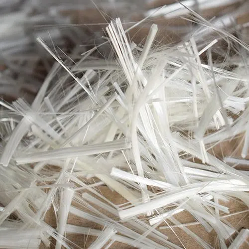
About forklift
A forklift Truck is a powered industrial truck used to lift and transport materials. The earliest forklift truck was inverted between 1914 and 1915 and put on the market since 1930s. After that, the increasing need of transporting military material during the World War 2 spurred the development of the Forklifts following the war, more efficient methods for storing products in warehouse were being implemented. Warehouse needed more maneuverable forklift trucks that could reach greater height. More new forklift model were made that filled this need. Since then, forklift trucks that could reach greater heights .More new forklift model were made that filled this need Since then, forklift truck have become indispensable equipment in manufacturing and warehousing operations . In 2011, the size of the forklift manufacturing industry was nearly $ 27 billion
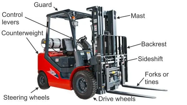
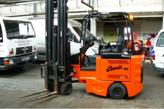
Types of Forklifts
Forklifts come in a variety of sizes, configurations and weight- lifting capacities.
Class1: In terms of power source, there are electric- powered forklifts and gas- powered ones
Class2: in terms of configuration, there are counterbalance forklifts (four-wheel and three wheel), reach truck, order picker,
Design of Arm
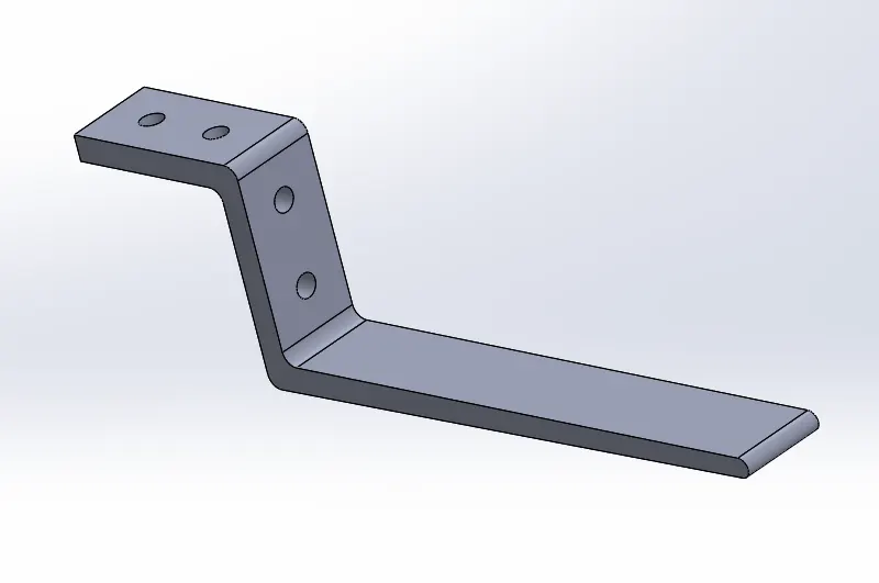
First we will create all parts with proper dimensions that needed in our design, then we will assemble some of them as subassembly and put them with the rest altogether as an entire assembly. 2D sketch of forklift arm is designed in solid works. The total length of arm is 580 mm and the height is 170mm with thickness of 20mm as shown in figure
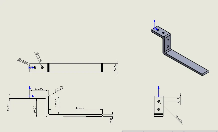
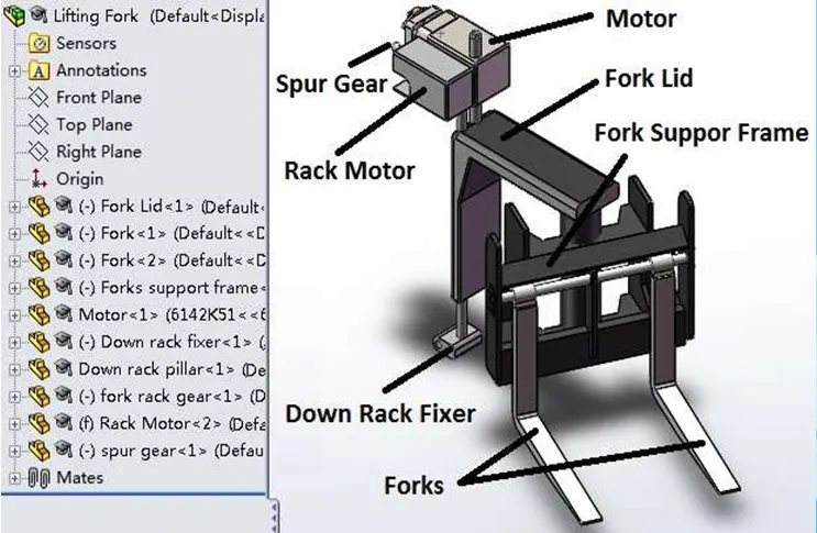
The 3-D sketch of arm is shown in fig. The lifting fork is one of the most important parts of the forklift its job is to grab the load for shelves and move it up and down during the loading process. It is placed in front of the whole truck and connected to the operator cabin first we will introduce the subassembly and its components then we will demonstrate how lifting fork work by demonstrating its three basic movement
There are two forks installed in front of the support frame and the support frame is attached to the fork lid thought a pillar which is rotatable to provide the lifting fork system with a rotation movement there are two axles connecting the fork support frame with its two motor and rack fixer. One motor lifts the fork lid and the other one (rack motor) move the whole system horizontally. We will discuss these three motions in detail in the next section the down rack fixer connect the fork lid with operations cabin to make sure the entire system is stable in front of the truck
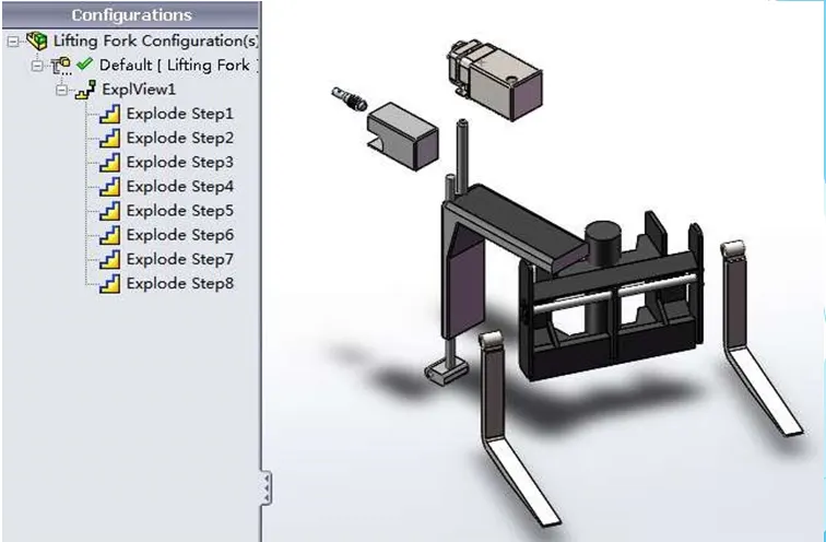
Movement of lifting fork can be simplified as three basic motions horizontal, vertical and rotation. Here we will use the lifting fork assembly and the cabin to demonstrate them. First the forks are at resting positions the forks usually rest on one side of the truck
Analysis of glass fiber Arm on Ansys:
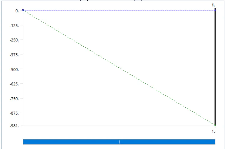
This sections covers both the static and dynamic (due to fatigue) analyses of the forks. For the static analysis, we already got the result that the maximum loading capacity of this forklift is 1000kg. 1000kg convert to force is about 10000N. There are two forks and the structure is symmetrical, so each one of them will carry half of the force, which is 5000N. As figure 6.2 shows this is model we get after meshing. Then we apply a normal 981N force on the surface of the fork. Since the top of the fork will be attached to a bar from support frame, so we will fix the top of the fork as its boundary conditions
Boundary conditions
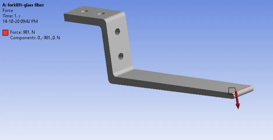
force of 981 is applied on free end in Y direction and forces from other direction is taken zero
Total Deformations
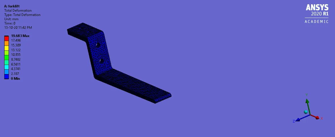
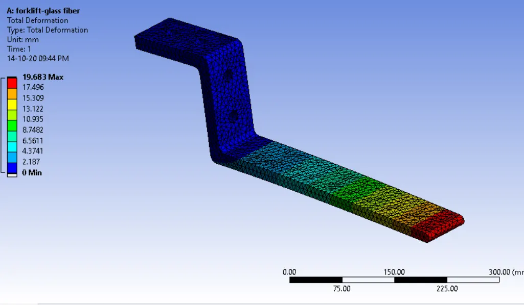
Total Deformation in arm due to force. Maximum Deformations will be 19.683 mm
Maximum Principal stress
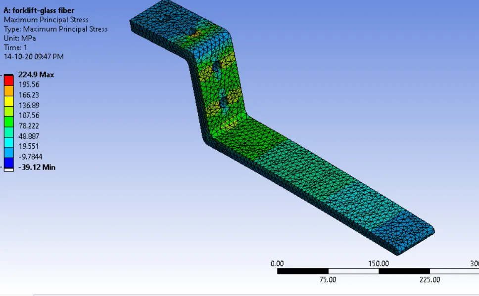
Maximum principal stress induced is 224.9 Mpa
Safety Factor
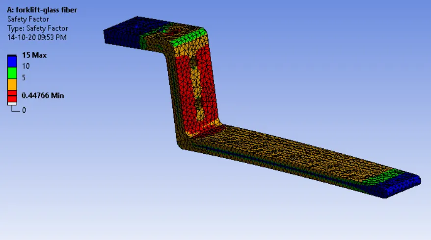
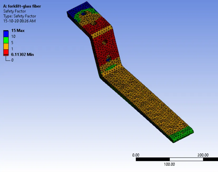
factor of safety of arm is 15
Tensile Test:
Compressive Test:
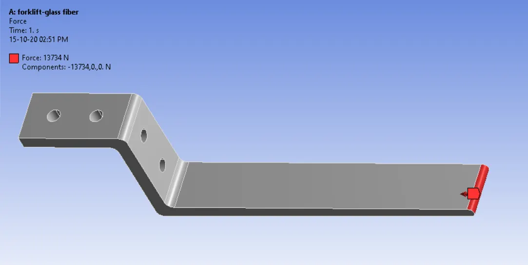
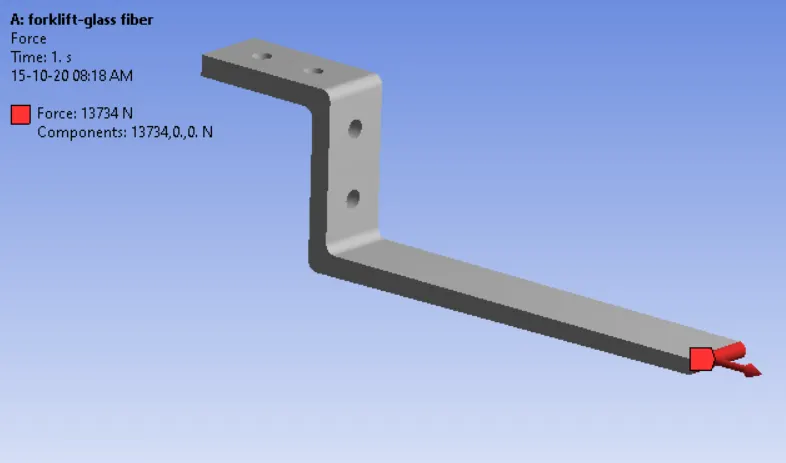
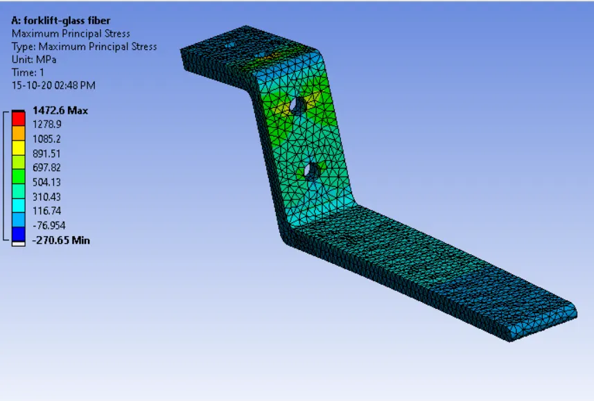
Force of -13734N is applied in X-direction and forces from other directions is taken zero
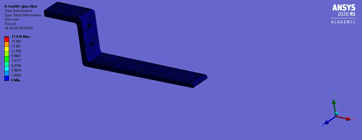
The compression specimen is prepared is prepared as per the ASTM D638 standard A compression test involves mounting the specimens ina machine and subjecting it to the compression. the compression process involves placing the test specimens in the testing machine and applying compress to it untile it fractures the compress forces is recorded as a functions of displacement. During the applications of compressions, the elongations of the gauge section is recorded against the applied forces
lenght=430mm, width= 70mm, thick= 20mm
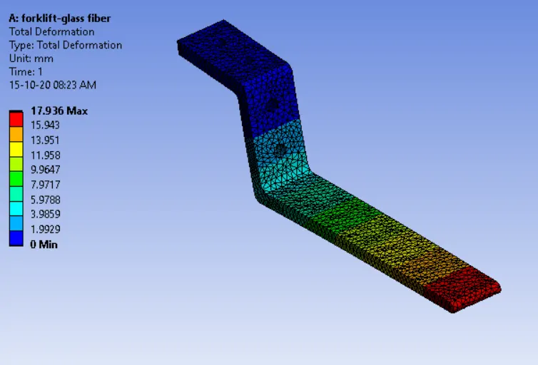
Total Deformations
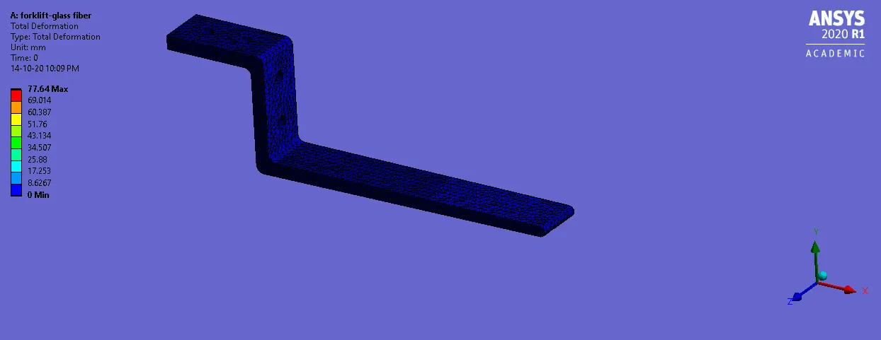
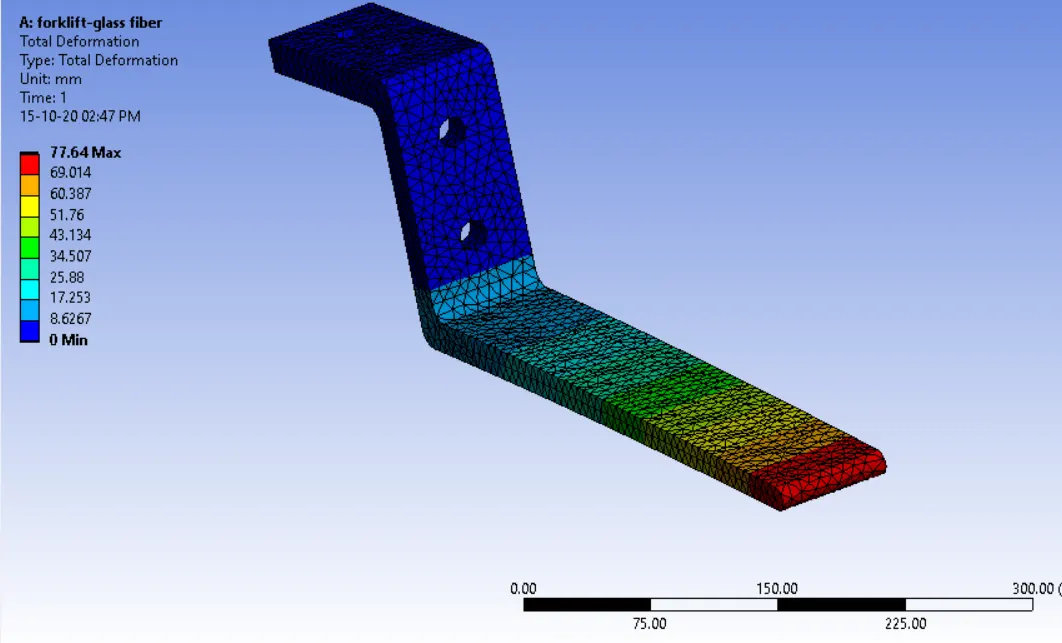
Total deformations in arm due to force. Maximum deformations will be 77.64`z
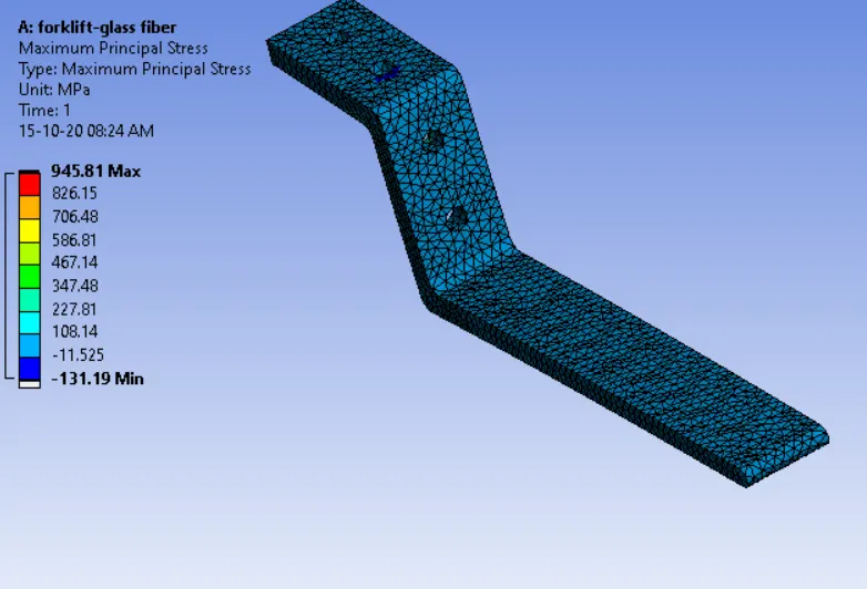
Maximum Principal stress
Safety Factor
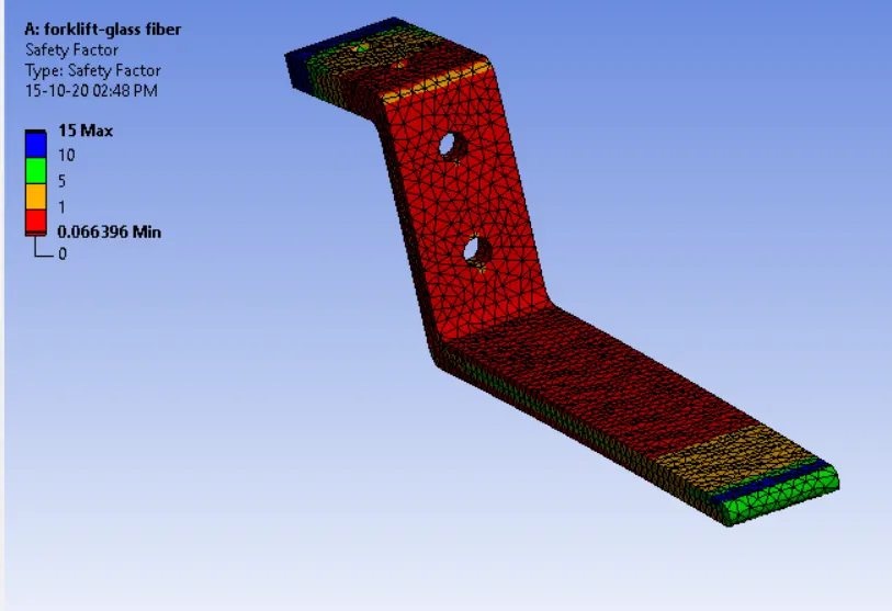
factor od safety of arm is 15
Units
| Unit System | Metric (mm, kg, N, s, mV, mA) Degrees rad/s Celsius |
|---|---|
| Angle | Degrees |
| Rotational Velocity | rad/s |
| Temperature | Celsius |
Model
Geometry Model > Geometry
Model > Geometry > Parts
Model (A4) > Materials
| Object Name | Materials |
|---|---|
| State | Fully Defined |
| Statistics | |
| Materials | 1 |
| Material Assignments | 0 |
Coordinate SystemsModel > Coordinate Systems > Coordinate System
Mesh
Model > Mesh
Static Structural
Model > Analysis
Model > Static Structural > Analysis Settings
Model > Static Structural > Loads
FIGURE 1
Model > Static Structural > Force
Solution (A6)
Model Static Structural > Solution
Model > Static Structural > Solution > Solution Information
Model > Static Structural > Solution > Results
Model > Static Structural > Solution > Total Deformation
Model > Static Structural > Solution > Total Deformation
| Time [s] | Minimum [mm] | Maximum [mm] | Average [mm] |
|---|---|---|---|
| 1. | 0. | 19.683 | 4.9726 |
Model > Static Structural > Solution > Maximum Principal Elastic Strain
Model > Static Structural > Solution > Maximum Principal Elastic Strain
| Time [s] | Minimum [mm/mm] | Maximum [mm/mm] | Average [mm/mm] |
|---|---|---|---|
| 1. | -3.0062e-006 | 2.8224e-003 | 2.8301e-004 |
Model > Static Structural > Solution > Maximum Principal Stress
Model > Static Structural > Solution > Maximum Principal Stress
| Time [s] | Minimum [MPa] | Maximum [MPa] | Average [MPa] |
|---|---|---|---|
| 1. | -39.12 | 224.9 | 17.194 |
TABLE 16
Model (A4) > Static Structural (A5) > Solution (A6) > Fatigue Tools
FIGURE 5
Model (A4) > Static Structural (A5) > Solution (A6) > Fatigue Tool
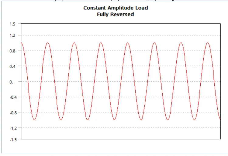
FIGURE 6
Model > Static Structural > Solution > Fatigue Tool
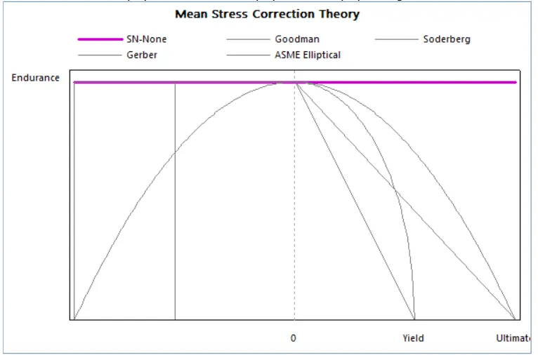
Model > Static Structural > Solution > Fatigue Tool > Results
Model > Static Structural > Solution > Fatigue Tool > Safety Factor
| Time [s] | Minimum | Maximum | Average |
|---|---|---|---|
| 1. | 0.44766 | 15. | 5.9124 |
Material Data
Glass fiber
Glass fiber > Constants
| Density | 2.57e-015 kg mm^-3 |
|---|---|
| Coefficient of Thermal Expansion | 1.2e-005 C^-1 |
| Specific Heat | 4.34e+005 mJ kg^-1 C^-1 |
| Thermal Conductivity | 6.05e-002 W mm^-1 C^-1 |
| Resistivity | 1.7e-004 ohm mm |
Glass fiber > Color
| Red | Green | Blue |
|---|---|---|
| 132 | 139 | 179 |
Glass fiber > Compressive Ultimate Strength
| Compressive Ultimate Strength MPa |
|---|
| 0 |
Glass fiber > Compressive Yield Strength
| Compressive Yield Strength MPa |
|---|
| 1.08e-003 |
Glass fiber > Tensile Yield Strength
| Tensile Yield Strength MPa |
|---|
| 3.5e-003 |
Glass fiber > Tensile Ultimate Strength
| Tensile Ultimate Strength MPa |
|---|
| 460 |
Glass fiber > Isotropic Secant Coefficient of Thermal Expansion
| Zero-Thermal-Strain Reference Temperature C |
|---|
| 22 |
Glass fiber > S-N Curve
| Alternating Stress MPa | Cycles | Mean Stress MPa |
|---|---|---|
| 3999 | 10 | 0 |
| 2827 | 20 | 0 |
| 1896 | 50 | 0 |
| 1413 | 100 | 0 |
| 1069 | 200 | 0 |
| 441 | 2000 | 0 |
| 262 | 10000 | 0 |
| 214 | 20000 | 0 |
| 138 | 1.e+005 | 0 |
| 114 | 2.e+005 | 0 |
| 86.2 | 1.e+006 | 0 |
Glass fiber > Strain-Life Parameters
| Strength Coefficient MPa | Strength Exponent | Ductility Coefficient | Ductility Exponent | Cyclic Strength Coefficient MPa | Cyclic Strain Hardening Exponent |
|---|---|---|---|---|---|
| 920 | -0.106 | 0.213 | -0.47 | 1000 | 0.2 |
T
Glass fiber > Isotropic Elasticity
| Young's Modulus MPa | Poisson's Ratio | Bulk Modulus MPa | Shear Modulus MPa | Temperature C |
|---|---|---|---|---|
| 73500 | 0.21 | 42241 | 30372 |
Glass fiber > Isotropic Relative Permeability
| Relative Permeability |
|---|
| 10000 |
Result and Discussions
The use of glass fiber materials in the different field is increasing day by day due to their improved properties. Engineers and scientists are working together for number of year for finding the alternative solutions for the high solution materials. In the present study natural fibers are added to the glass fiber reinforced composite material and their effect on mechanical properties is evaluated and their properties
Advantages:
- High Temperature Resistance
- Corrosions-resistance
- High tensile Strength
- Electric Resistance
- Smooth migrations
- It can be easily be mounded into any shape and size
Disadvantage:
- Needs to be re-gel Coated about every five years and can result in airborne fibers
- Loses effective if insulations becomes wet or damp
- Complex Shapes are difficult to Manufacture
Application:
- Forklifts are typically put to use in Distributions center or warehouse
- They are also used for transporting Drums, crates or stacked boxes.
- One of the most common uses of a forklifts is for indoor and outdoor materials movement
- Constructions Sites
- Warehouse
- Recycling Operations
- Dockyards
Fork Analysis
Forklift Loading parts are responsible for picking up the Load and carry it during the transportation. in this process, there are two kinds of failure: sudden fracture due to the Heavy Load and Fatigue Fracture due to the Vibration caused by uneven ground during the transportations. we will do stress analysis targeting both conditions
we divides a complex shape into lots of smaller element when the engineering design problem are too complicated a find a closed -form solution for their govering equilibrium equations . instead it converts the equilabrium equations of a continuum into a intergal , in another world , finite element method analyzes a whole design at the element level .Furthermore, as stated in finite element theory, using different meshing element would cause different analysis results. we Will use the actual results to prove this conclusions
Conclusions
This project is mainly about a new design of a forklift. We did some research on the products that already exists in the market for use .then we studies in more details about how forklifts work and the primaryy structure and some new design ideas were proposed. After comparing their advantage / Disadvantage, we finally have our new design proposal settled and finished the 2D design schematic
We want to make sure our forklift design here meets the safety requirements for use. We use mass ad centre of gravity measurements to run our stress analysis, under both resting and loading conditions. Then we discuss the stability triangle and how our forklift design is stable under resting conditions and its centre of weight stays inside the safety triangle. In working conditions, we working conditions, we change the load to see how centre of gravity of the whole truck change and get the capacity of our forklift, which is 1000 kg
We studied the design to ensure that it will meet the functional requirement like the stress analysis .first we ran the analysis on one of the two components in the stress analysis. First we ran the analysis on one of the two components in the lifting fork system, the fork. Not only we want to see if it is safe for use, we also want to see how different element type can change the result of the meshing model and the value so stress, strain and displacement. Then we ran test on the other component of the lifting system, the support frame. We also performed analysis on one of the most important subassembly, Scissor lift. The result are very satisfying , they are all safe for use
Reference
- LP Gas Cushion Tire Lift Trucks Brochure, Caterpillar, MFCA, 2013
- High Capacity Forklift Trucks H8.00-12.00XM-6, H13.00XM-16.00XM-6, HYSTER, 2013
- Top 20 Lift truck suppliers, Josh Bond, Modern Materials Handling,2013
- Toyota Material Handling Range, TP-Technical Publications, Sweden, 749803-040, 1304