Week 4 -Wire Bending Challenge
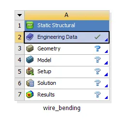
Understanding the effect of wire bending using Ansys workbench
Objective: To perform an structural analysis to simulate the bending of a wire considering three different case setup and compare their results.
Simulations setup
Case (1) – copper alloy (Non-linear)
Case (2) - Aluminum alloy (Non-linear)
Case (3) – Magnesium alloy (Non-linear)
Structural Analysis:
Structural analysis is the process of calculating and determining the effects of loads and internal forces on a structure or an object
Input Geometry
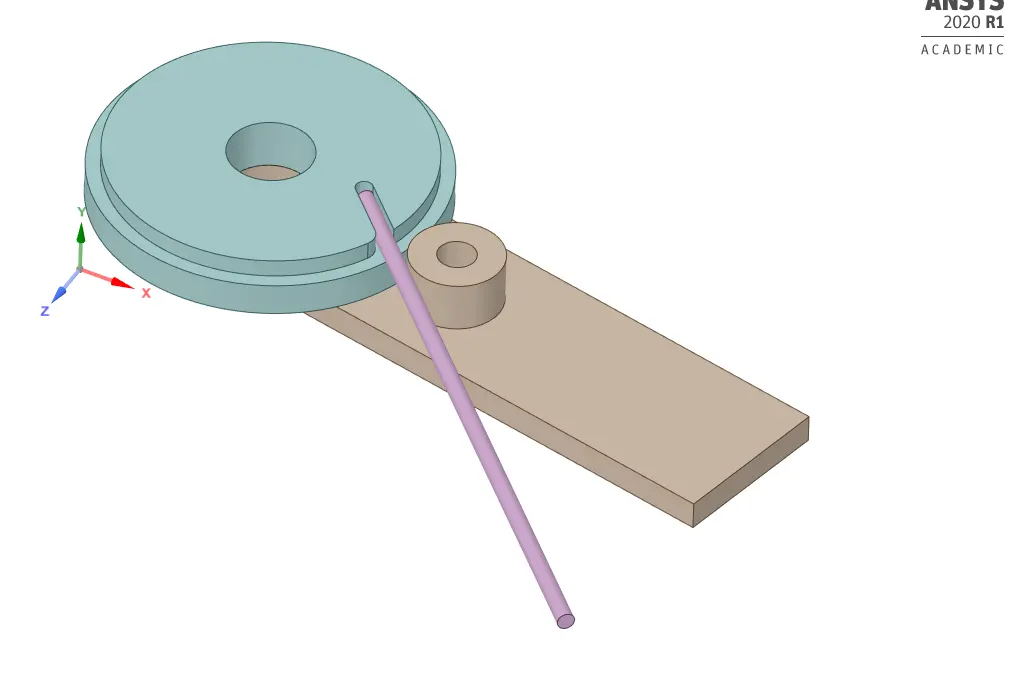
The CAD model is imported and viewed using space claim,
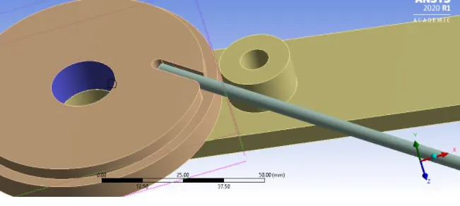
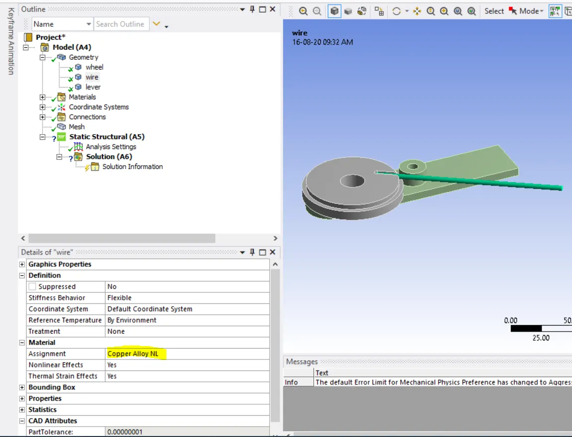
The geometry includes the following component wheel, wire, and lever
Material:
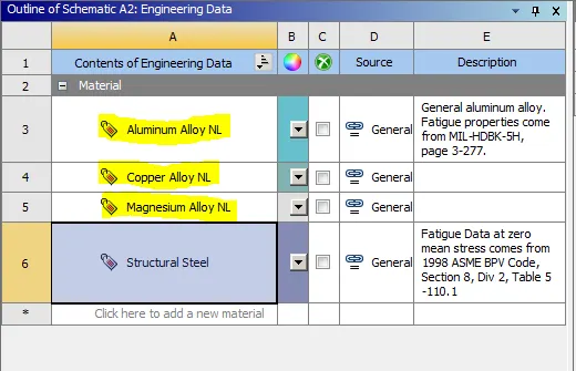
Wheel- structural steel
Wire- copper Alloy/ Aluminium alloy/ magnesium Alloy
Lever-structural steel
Contacts:
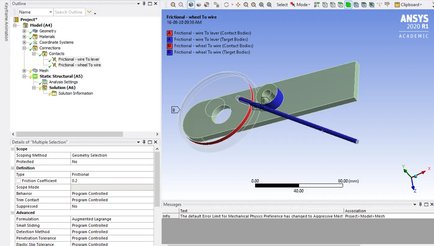
Two frictional contact (f=0.2) are setup one between the wire and lever. The other between the wire and the wheel as shown below.
Contact settings
Formulation- Augmented Lagrange
Normal Stiffness factor-0.1
Update stiffness-Each iterations
Interfaces treatment – Add offset, Ramped Effects
Joint creations
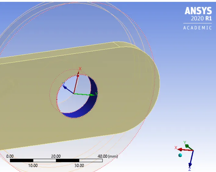
A body-ground revolute joint is defined by selecting the inner surfaces of the lever hole, with Z-axis as rotational axis
Mesh
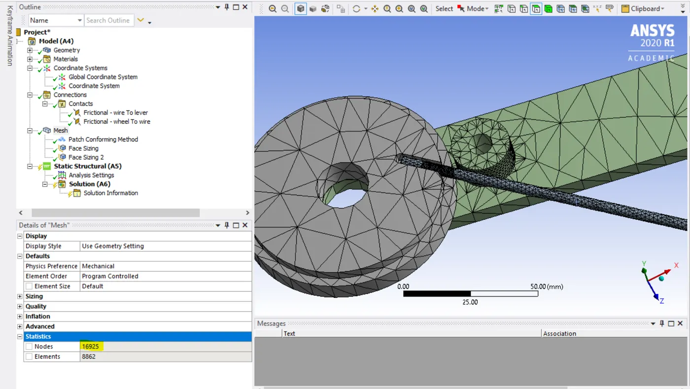
The mesh method is for all bodies are set to Tetrahedrons. The critical faces shown below are given a mesh sizing of 1.8mm
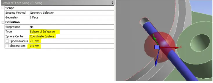
The mesh sizing is made finer (0.8) by choosing a sphere of influence(r=7mm) at the co-ordinate system shown
Analysis setting:
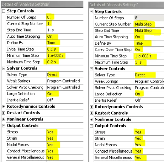
The analysis is set up for 8 steps with the following setting for all the steps.
When stabilizations are activated, it adds dampers to all the nodes. When the large displacement nodes try to move, the force is added to balance them thus favouring convergence. Energy Dissipations Ratio is given value between 0 and 1
step 1 steps 2-8
Boundary conditions
- The wheel is fixed by assigning the inner surface of the wheels hole as a fixed support .
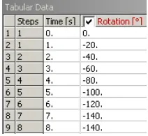
- The lever joint is given a rotation of about 140 degrees such that the wire bends around the wheel
Solutions:
All the necessary output variable are selected such as von Mesis stress, stress intensity, equivalent strain etc.
Results
The maximum time step was 2 the solver converged at various time steps and dropped down to a lower time step value.
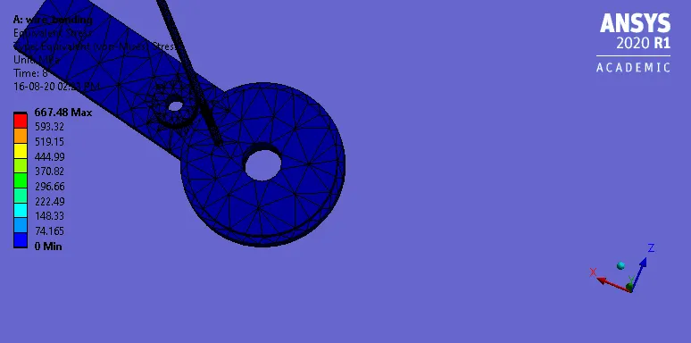
Case (1) – copper alloy (Non-linear)
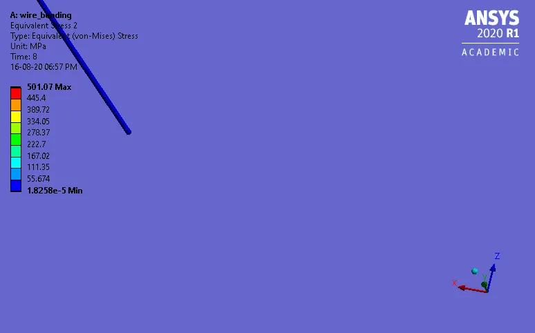
Equivalent stress
Equivalent strain
Case (2) - Aluminum alloy (Non-linear)
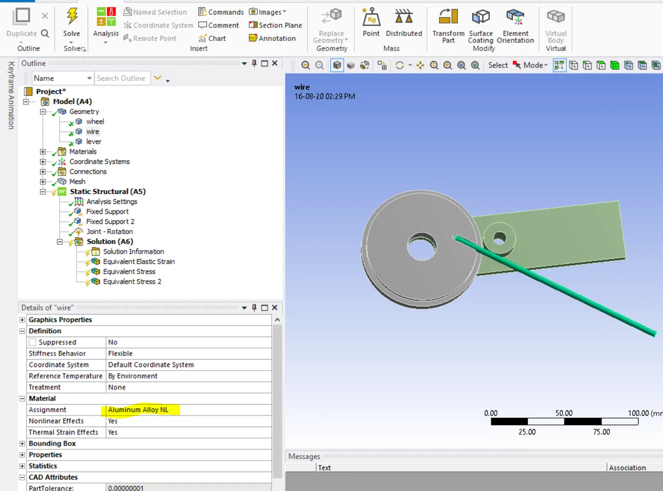
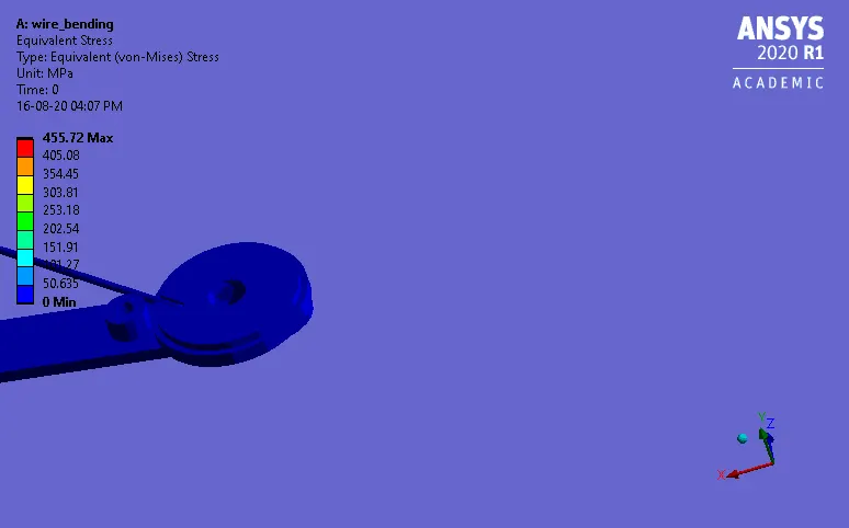
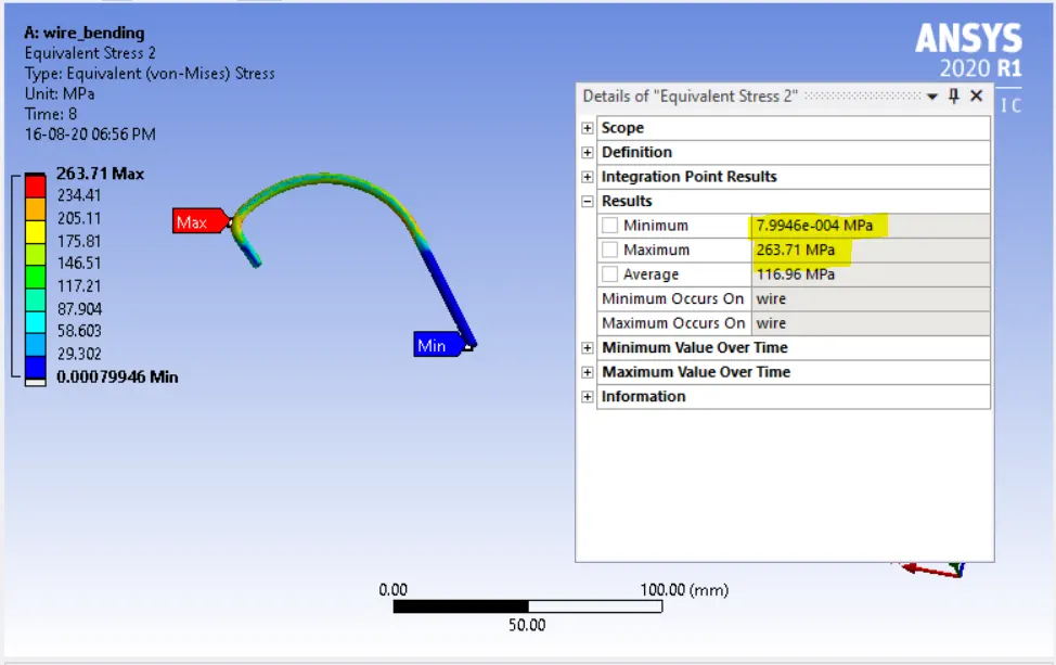
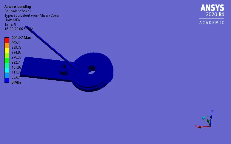
Equivalent stress
Equivalent strain
Case (3) – Magnesium alloy (Non-linear)
Equivalent stress
Equivalent strain
|
copper alloy (Non-linear) |
Aluminum alloy (Non-linear) |
Magnesium alloy (Non-linear) |
| Equivalent stress | ||
|
|
|
|
| Equivalent strain | ||
|
|
|
|
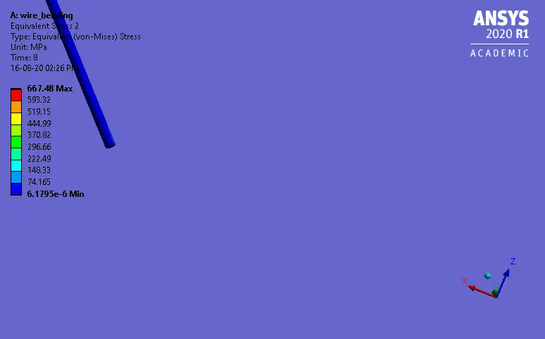
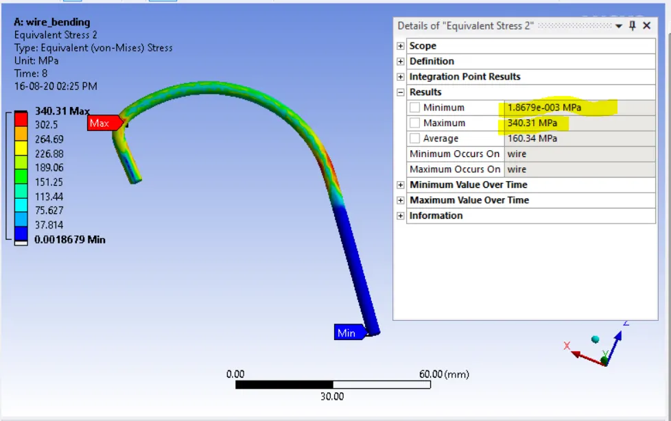
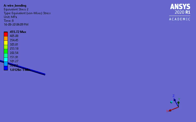
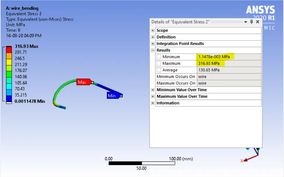
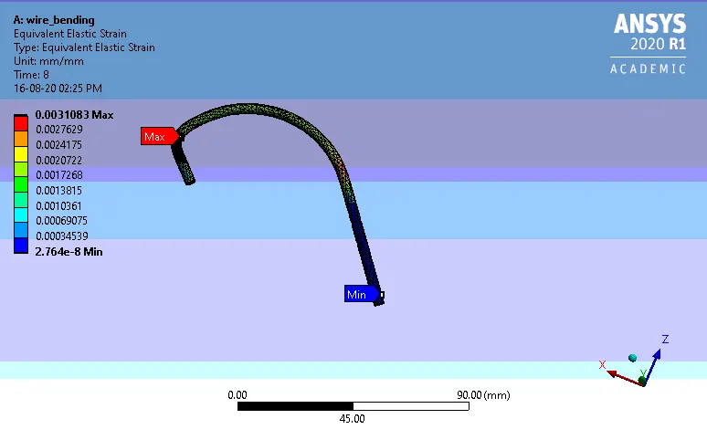
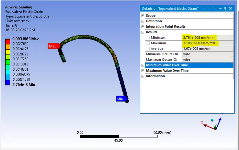
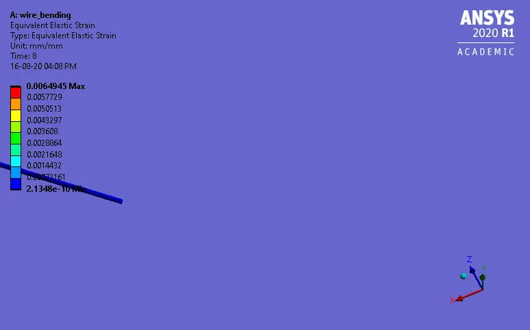
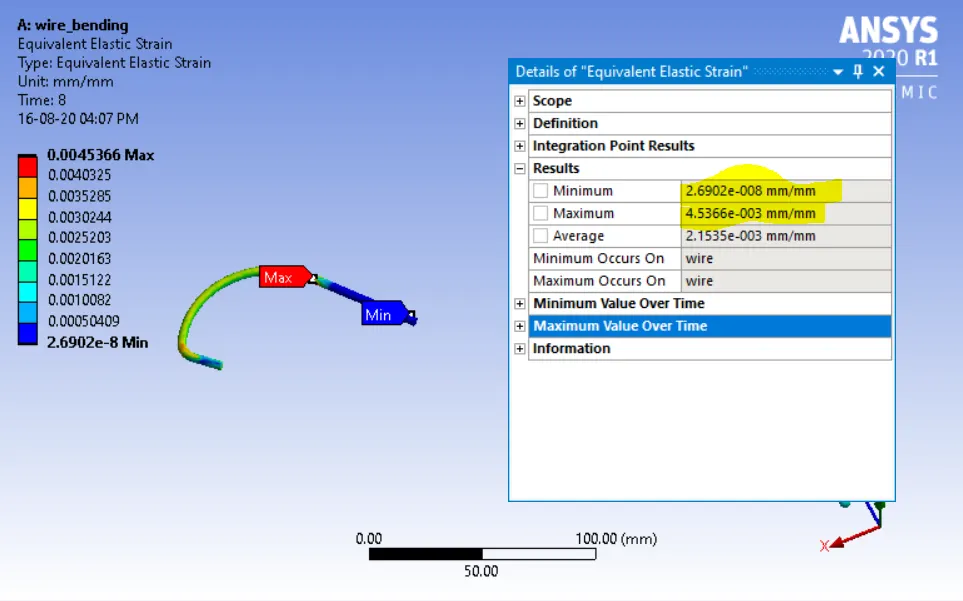
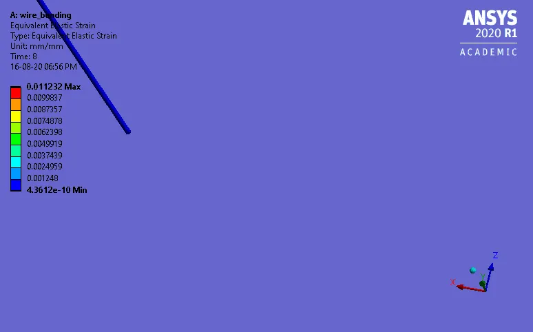
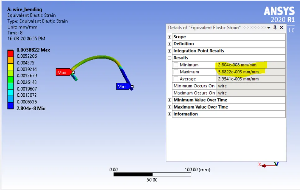
Based on the obtained results, we can find the aluminum alloy NL has the highest capacity to withstand the load while bending than the other two materials with the highest Equivalent elastic strain than the other two.
Conclusions
Thus structural analysis to simulate the bending of a wire considering three different case setup cases has been performed and the results were compared