Section Modulus calculation and optimization
A report on SECTION MODULUS
Section Modulus:
- Section Modulus is a geometric property used to calculate the bending stresses in a structural member.
- Mathematically section modulus is define as the ratio of total moment resisted by the section to the stresses induced in the extreme fibre.
- It gives information about how much load the structure can sustain without failure. Hence it determines the load bearing capacity of the structure.
- Higher the section modulus higher the moment of resistance. Hence the load bearing capacity becomes high.
S = I/Y
where,
S = section moduluds
I = moment of inertia
Y = distance between centroidal axis and outer most layer or fibre
Section geomerty and inertia calculation using NX:
- To get the section geomerty of the hood about Y axis, the intersetion curve is been used.
- First make sure that the hood assembly is activated and both inner and outer panel is been thickened.
- Select the 'intersection curve' option in curves tab. a window will pop up which will be ask for select face and specify plane. Before that in selection scope, 'entire assembly' should be selected. After selecting the hood, next is to specify the plane along which the intersection curve needs to get on the hood.
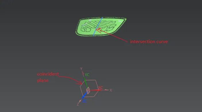
- To get the intersection curve about Y axis we need datum plane at the middle of the hood along the Y axis.
- For that the datum plane is created at 50% of arc length on the previous curve perpendicular to it.
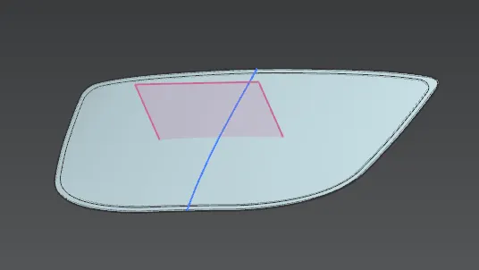
- Now the intersection curve is been generated using similar method used as previously.
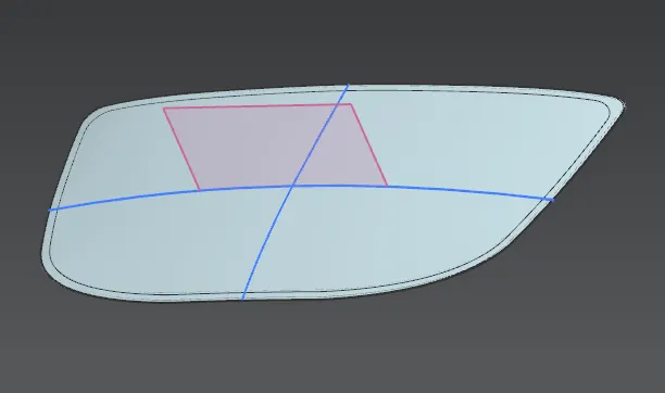
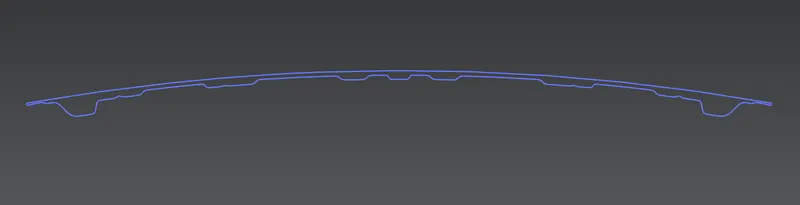
- Now the section geometry is formed along y axis. we can see it if we hide the inner and outer panel.
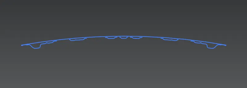
- To calculate the inertia for this perticular geometry using NX, it must be a closed profile.
- For that a sketch is been created on a plane and this curve is been projected on it. After that the open areas get closed by sketching splines in between.
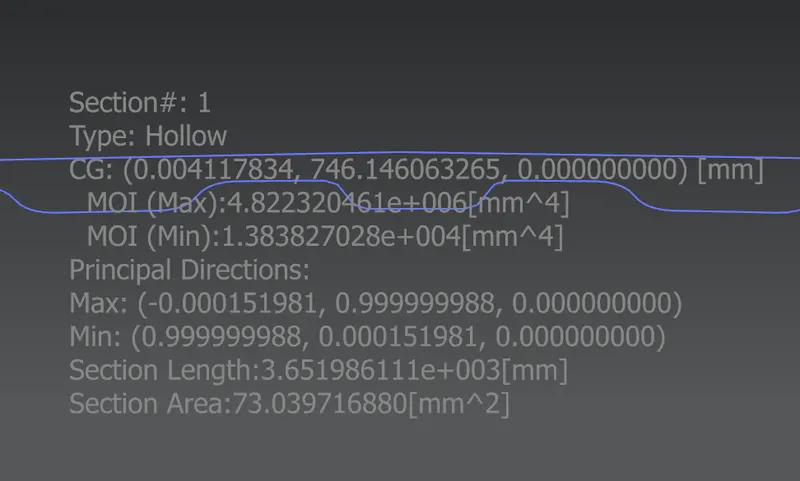
- To calculate inertia for this section there is a command called 'section inertia analysis'. using this command the maximum and minimum inertia is been calculated.
- To get the total distance of the section along y axis we can sketch two referece lines on the either ends and we can measure the distance between them using 'measure distance'.
- Hence L = 877.194 mm
Y = L/2 = 877.194/2
Y = 438.597
- Using above values we can determine the section modulus as follows.
S = I min/Y
= 1.383827028*10^4/438.597
= 31.551219 mm^3
- Now we can improve this value of section modulus by increasing the depth between outer panel boundry and inner panel boundry.
- This could be done by making changes in existing sketch of the section. The lower curve of the section is been offseted downward by 0.5mm and the geometry profile remains closed.
- The section inertia for new section is showned below.
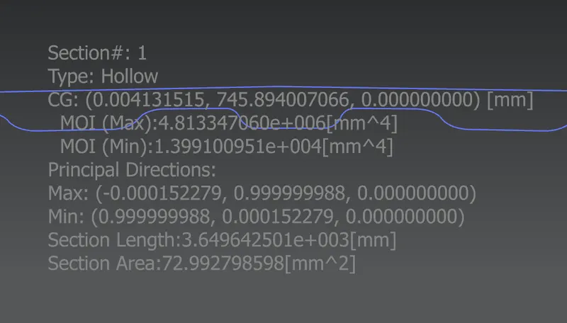
- Using this new inertia value we can determine the section modulus again and we can calculate % increase in section modulus.
S1 = I min1/y
= 1.399100951*10^4/438.597
= 31.899464 mm^3
- % change in section modulus
% change = (S1 - S / S) * 100
= ((31.899464 - 31.551219) / 31.551219) * 100
= 1.103 %