Wiring harness design in CATIA V5 - 3D modeling Week 4 Challenge
A report on routing a harness layout in electrical workbench
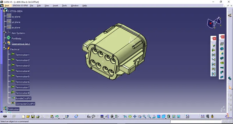
1) Defining all the connectors electrically and storing it in a catalogue document
- download all the given connectors from te.com and unzip it.
- open any of the connector mentioned in the given layout in catia's part design workbench
- give the geometrical parameters (point,axis) to it on it's connector connection and bundle connection side
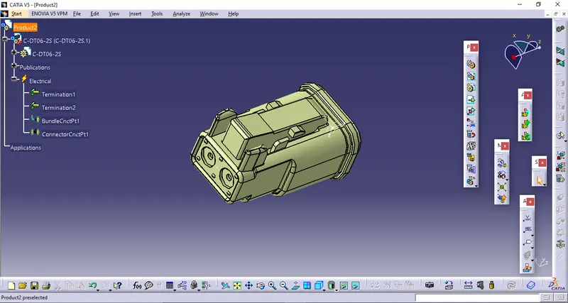
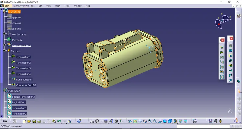
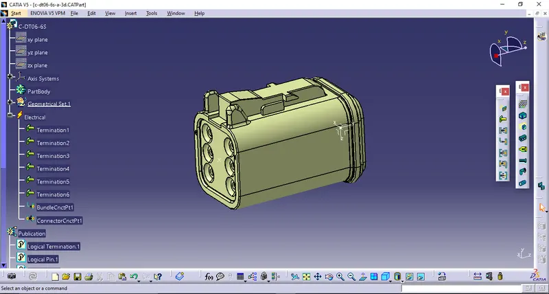
- switch the workbench to the electrical part design>select 'define connector option'>click on connector
- a window will pop up>give the no. of terminals accordingly>ok
- click on 'define bundle connection point'>click on the connector>a window will pop up.>click on the surface of the bundle connection side for representation>select the point>select the same surface for initial condition>ok.
- click on 'define connector connection point'>click on the connector>a window will appear>select point for the representation>select surface for contact>select y axis for coincidence>select x axis for the orientation>ok. now the connector is defined geometrically and electrically.
- save the connector.
- use the same process to define the remaining connectors and save all of them
- to create a catalogue for storing the connectors go to file>new>catalogue document>ok.
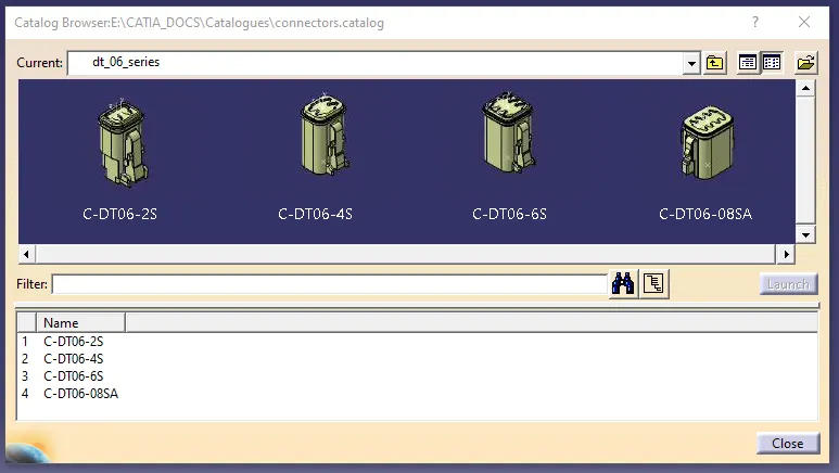
- a window will appear. select the add family option>a window will opo up>give the family name>select the type 'electrcal'>ok.>file>save>give the catalogue name>save
- open one of the connector in electrical part design workbench>click on 'store device option'>a window will pop up>brouse the catalogue and select it>select the family>ok.the connector has been stored in the catalogue.
- the same procedure can be used to store the remaining connectors.
2) Harness assembly
- prepare a 2d layout sketch in part design workbench with given dimensions using different sketch tools(line,point)
- switch the workbench to the assembly design with existing sketch
- click on catalogue brouser>brouse the catalogue in which the connectors are saved>open that one.
- double click on any single connector in order to bring it in the workbench>a small window will appear with the preview of the connector>click ok>close the catalogue window.
- now position that perticular connector closed to its place as shown in the given layout by using 'manipulate' option and by selecting respective axes to drag the connector along.
- place the compass on the connector by drag and drop method>once the compass placed on the connector properly> click on the connector>the compass will turned into green colour>click on the upper green dot of the compass and hold> move the mouse to orient the connector in 360 view>bring the bundle connection side opposite to its position point on the sketch>click on 'snap' option>select one of the longitudinal edge of the connector and select the line on which the position point is layed>the connector will get aligned with it>again select the 'snap' option>select the point of connector on bundle connection side>select the position point>the connector will get snap with its desire position.
- the similar procedure can be used to position all the remaining connectors.
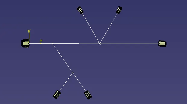
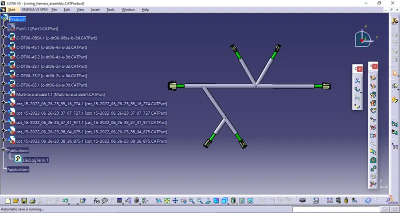
- now switch the workbench to the electrical harness assembly>select 'geometrical bundle' option>click on product1>click on 'multi-branchable document'>a window will appear>give the suitable diameter of the wire and bend-radius ratio>now hide the layout sketch by using tree so that the external curve could be added between the connectors>click on 'line' option> a window will appear>select line type as 'point-point'>draw a line between the connectors(dt06-8sa & dt06-6s) by snapping the points on them. the main wire path will form by this.>click on empty column next to the 'external curve' in 'branch defination' window>click on the path that has been created earlier>ok. the first multi-branchable will be form.
- click on 'add branch point'>select the multi-branchable>place the first point on 100mm distance from the left most connector>ok
- click on 'branch defination'>select the line tool>a window will pop up>select line type as 'point-point'>draw a line between branch point and right side dt06-4s connector's point>click on empty column next to the 'external curve' in 'branch defination' window>select the line which has drawn>ok. the wire will be formed between the branch point1 and dt06-4s connector.
- using this method of adding the branch points and constructing the erternal curves, the remaining connectors can be connected to the multi-branchable.
- after routing the wire with all the connectors, exit the electrical harness installation workbench by clicking 'exit' button on right side toolbar.
- click on 'add protective covering'>a window will pop up>click on brouse catalogue button>brouse the cot_tubes catalogue>select it>open the suitable corrugated tube>select it>click on multibranchable>the cot tube will be added on it>double click on 'start extrimity' present at the start of the cot tube>give the clearence value 30mm>ok.>double click on 'end extrimity' present at the end of the cot tube>give the clearence value 30mm>ok.
- using this method, the cot tube can be added to ramaining multibranchable and the clearence should be only at the connectors.