Advanced Sheet Metal Design Using NX Cad Challenge_1_Casing Design
A Report On Casing Design
Objective: To design a sheet metal casing using NX sheet metal application as per given guidelines.
Intorduction:
The NX sheet metal application is a powerful tool to design and develop the numerous sheet metal components in different sectors. It has been used in wide range of industrial sectors such as mechanical, automotive, structural design, medical sector and domestic sector etc. In this perticular exercise, the demonstration on designing of the casing have been carried out. Performing this practice gives the overall design methodology to create basic sheet metal parts with various features which will be
Design Methodology:
Recommended workflow to design simple sheet metal part-
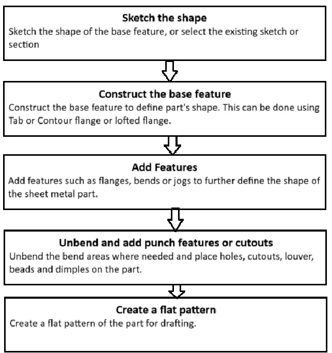
Features and commands used to generate the design:
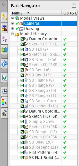
1) Sketching the base feature shape using sketch command
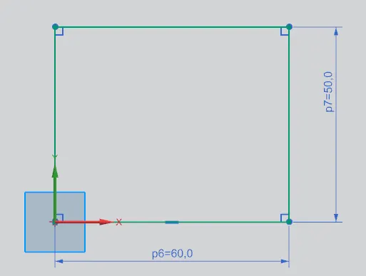
2) Tab
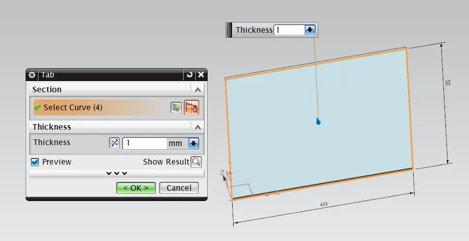
tab is the command used to which is used to create the base feature of the sheet metal part, i.e. the base sheet of the component from which other adjacent elements gets designed using other different commands.
3) Normal Cutout
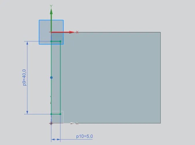
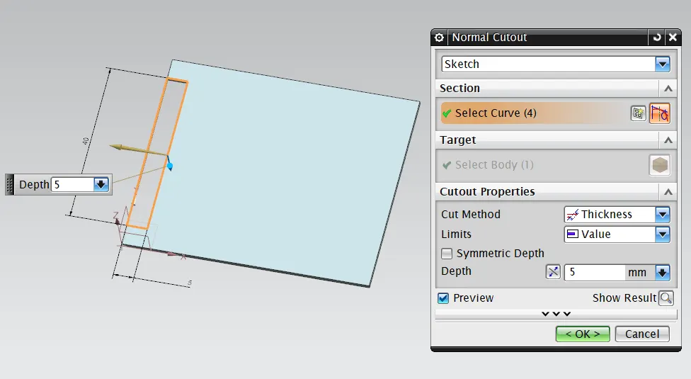 normal cutout is used to provide a cut on sheet metal of reqired peofile and this cut always makes 90deg angle with the sheet metal irrespective of it's own angle with the sheet metal.
4) Bend
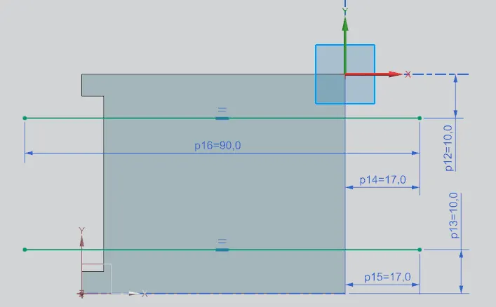
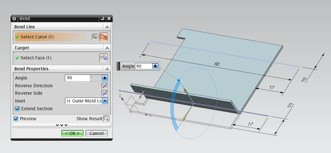
after sketching the lines on the part at required positions for the bend reference the bend command is further used to provide bend on the sheet metal with required bend angle.
5) Flange
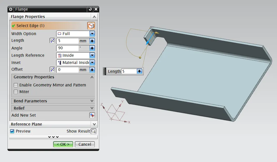
using flange command we can provide adjacent flanges to the existing sheet metal by selecting it's edges where required also we can provide different parameters such as bend angle, bend redius, bend relief, corner relief etc.
6) Break Corner
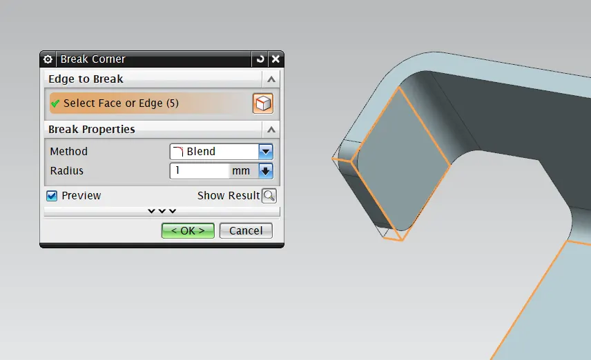
the break corner command is used to round the sharp corners of the sheet metal.
7) Unbend
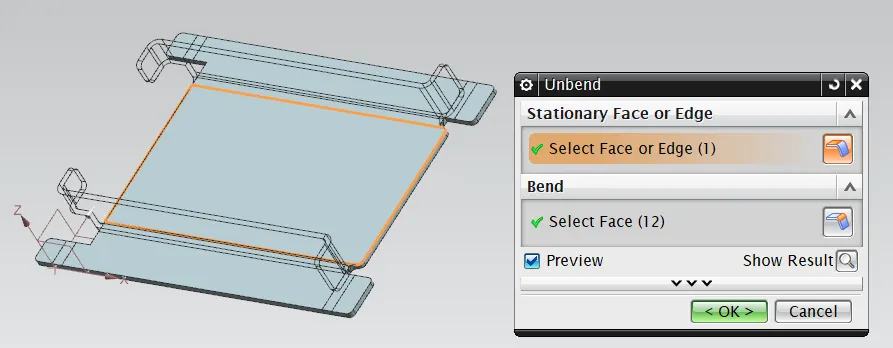
the unbend command is used to make the flanges flat w.r.t. the base feature.
8) Hole
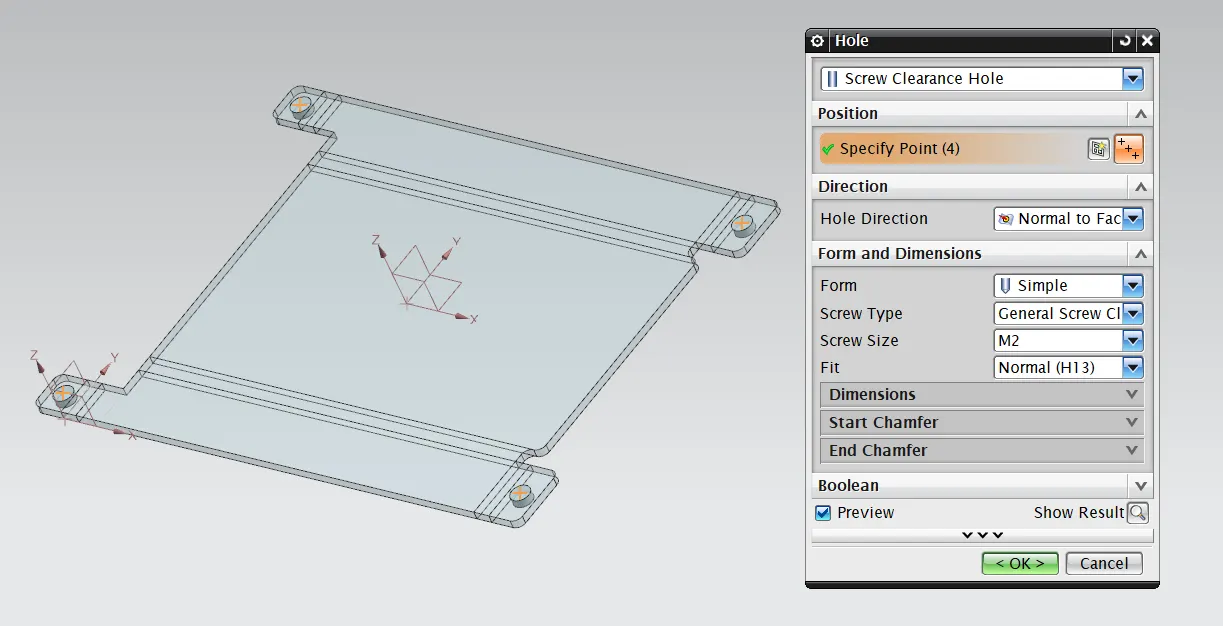
Using hole command, 'the screw clearance hole' has been porvided where the points were placed for it.
9) Dimple
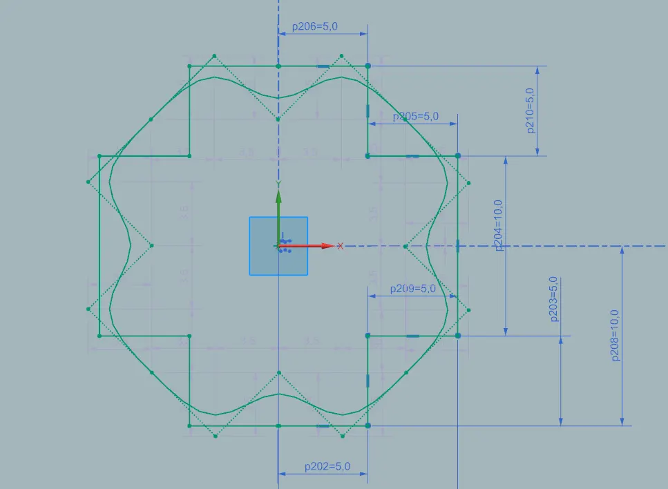
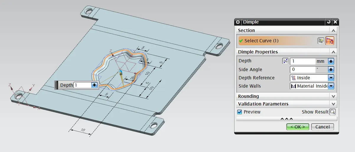
Firstly the sketch profile has been created for the dimple and using this profile the dimple is been provided using dimple command.
10) Bead
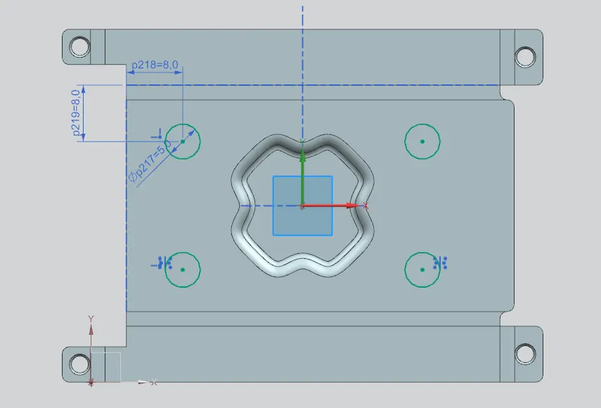
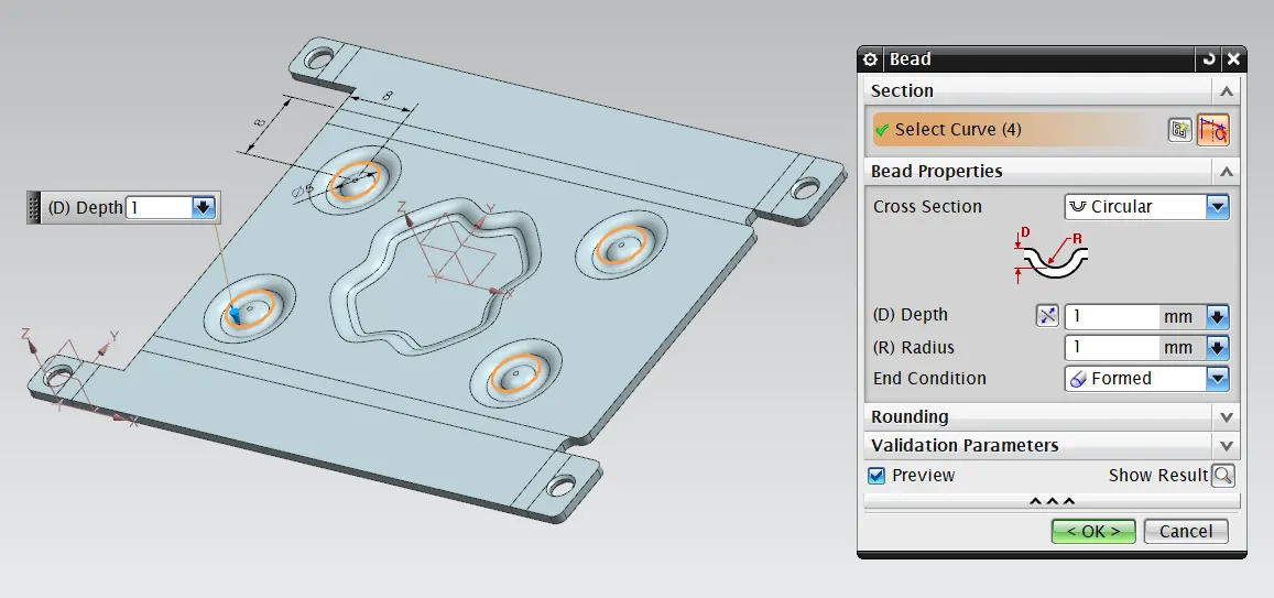
Firstly the sketch profile has been created for the bead, then using this profile the bead has been provided to the sheet metal using bead command.
11) Rebend
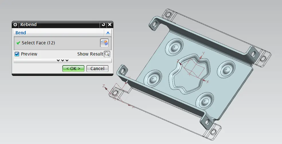
Using rebend command the sheet metal component gets it's bended form back.
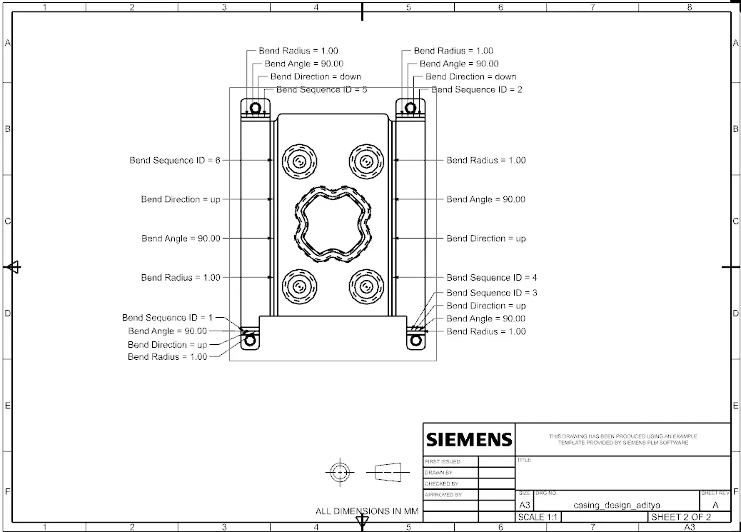
12) Flat Pattern
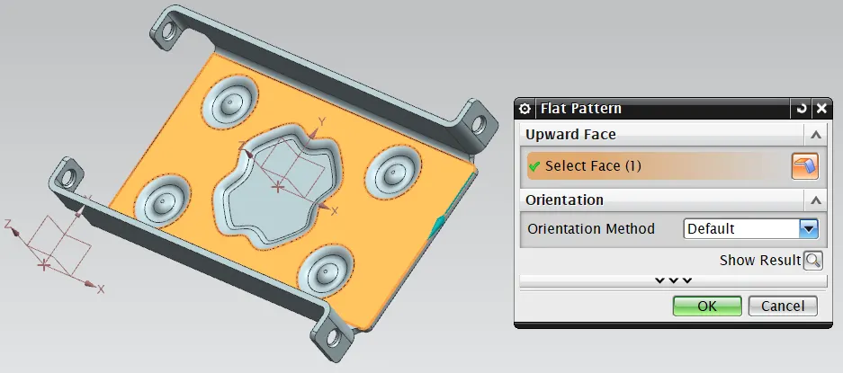
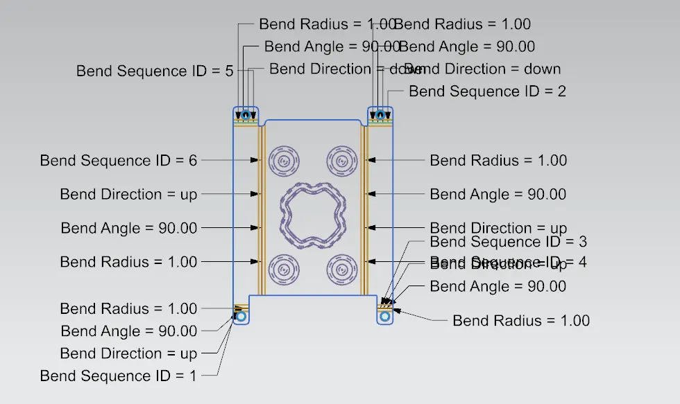
Using flat pattern command, a detailed 2d flat drawing got generated. By enabling the flat pattern view from model views in part navigator, the flat pattern could be seen in NX.
13) Drafting
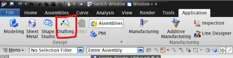
switch to the drafting application through the application tab.
then by selecting 'add base view' option to add the view of the model which is 'Flat Pattern' view.
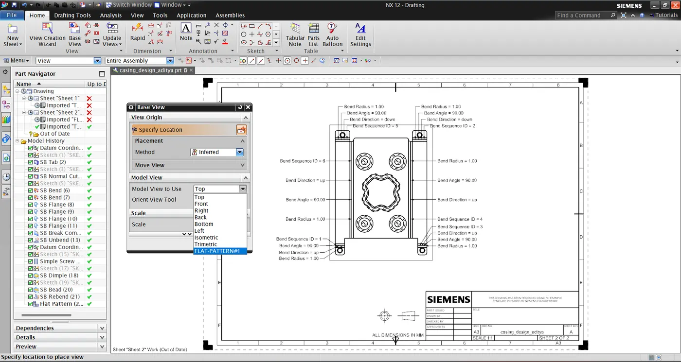
14) Part Navigator
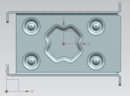
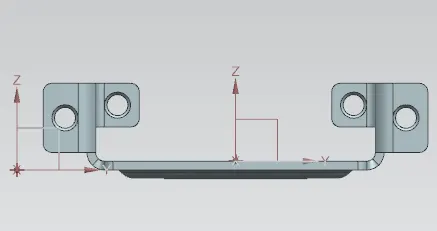
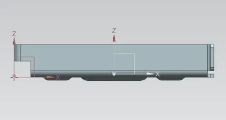
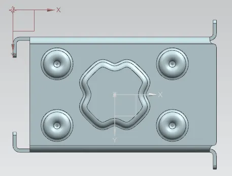
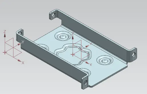
Screenshots Of The Part:
Conclusion:
In this way the casing design has been completed using NX sheet metal application by following the given guidelines.