Advanced Sheet Metal Design Using NX Cad Challenge_7_ Metal bracket-II
A Report On Metal Bracket Design
Objective: To design a sheet metal bracket using NX sheet metal application.
Intorduction:
The NX sheet metal application is a powerful tool to design and develop the numerous sheet metal components in different sectors. It has been used in wide range of industrial sectors such as mechanical, automotive, structural design, medical sector and domestic sector etc. In this perticular exercise, the demonstration on designing of simple sheet metal bracket have been carried out. Performing this practice gives the overall design methodology to create simple bracket and other similar sheet metal parts.
Design Methodology:
Recommended workflow to design simple sheet metal part-
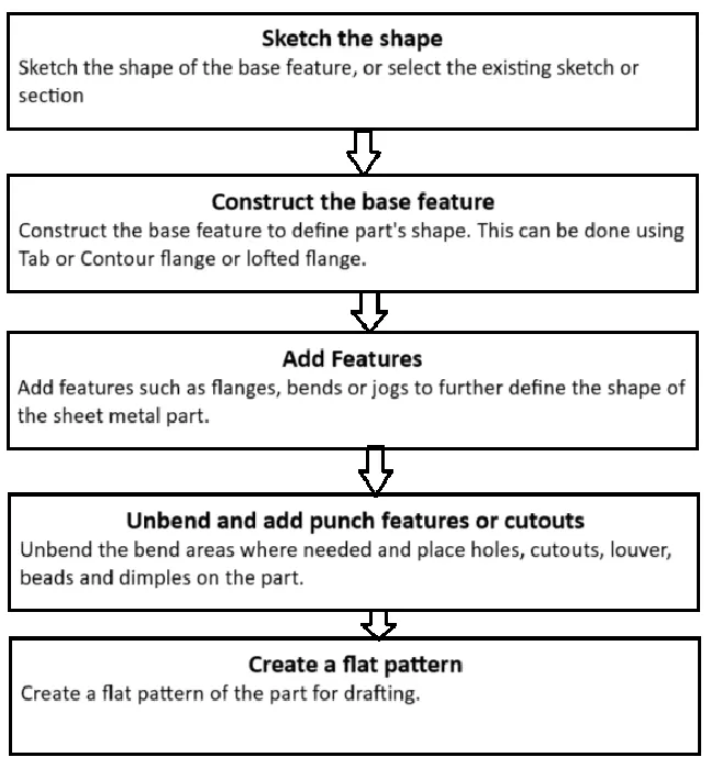
Features and commands used to generate the design:
1) Creating 2d sketch
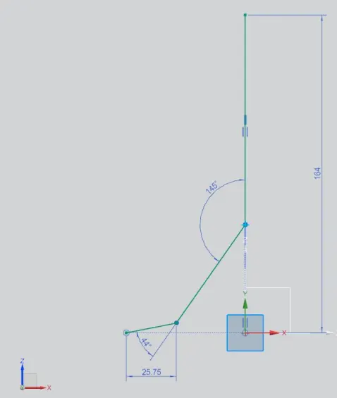
2) Contour Flange
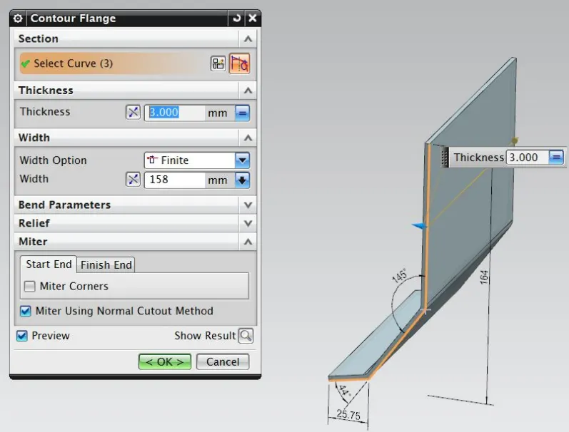
contour flange command creates a flange of selected sketch profile or a curve.
3) Normal Cutout
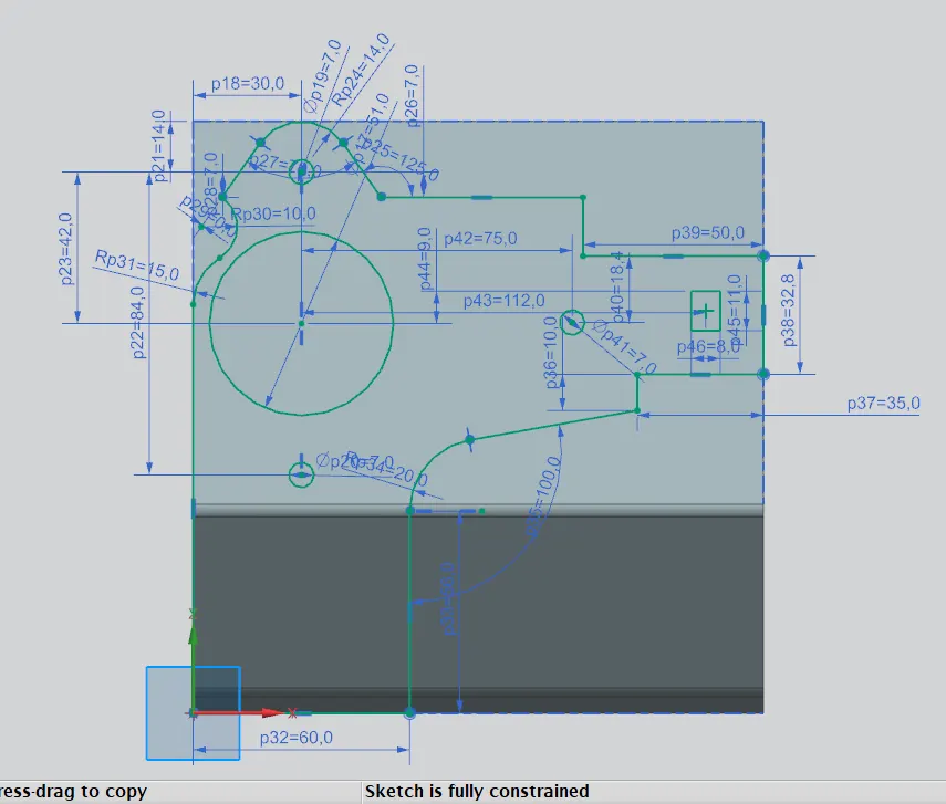
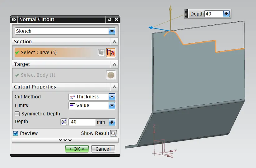
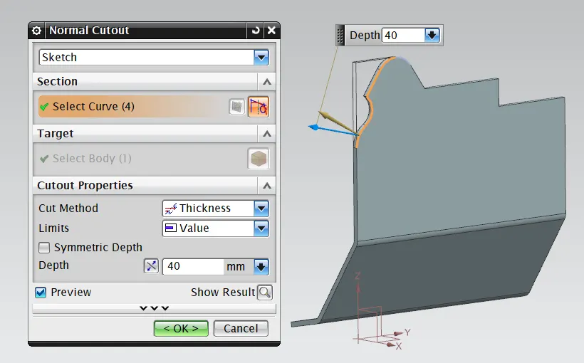
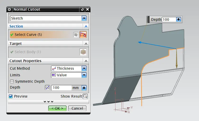
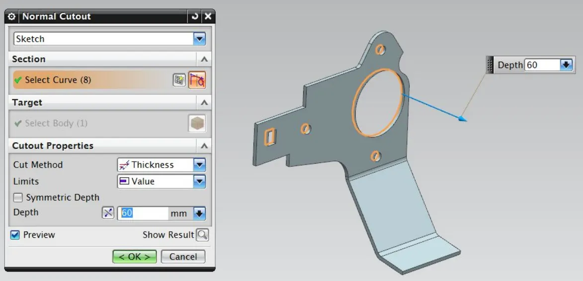
The normal cutout is used to provide the cut on the sheet metal of required sketch profile and this cut always makes 90 deg angle with the sheet metal irrespective of it's own angle with the sheet metal.
4) Break Corner
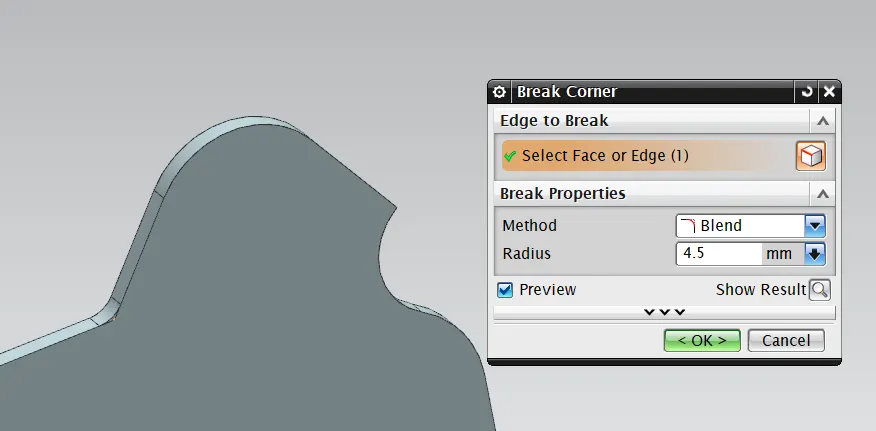
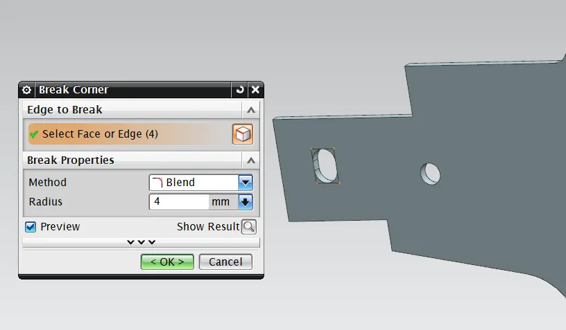
The break corner command is used to round the sharp edges of the sheet metal.
5) Unbend
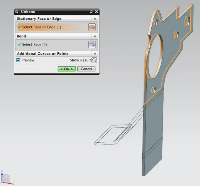
the unbend command is used to make the flanges flat w.r.t. the base feature.
6) Normal Cutout
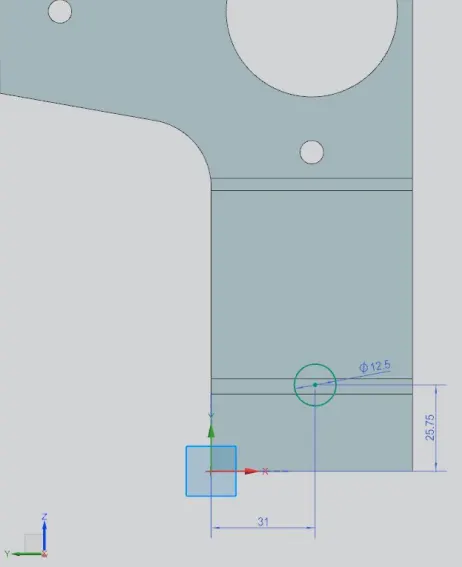
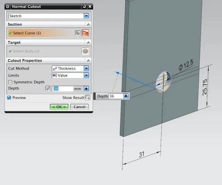
The normal cutout is used to provide the cut on the sheet metal of required sketch profile and this cut always makes 90 deg angle with the sheet metal irrespective of it's own angle with the sheet metal.
7) Rebend
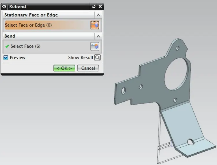
Using rebend command the sheet metal component gets it's bended form back.
8) Break Corner
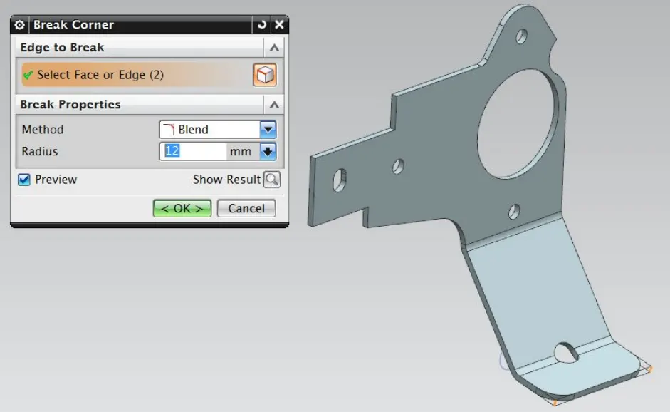
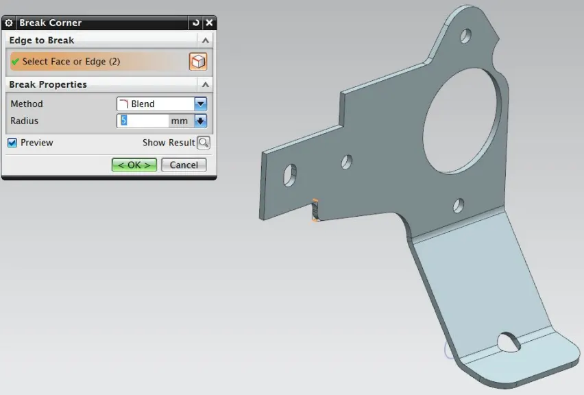
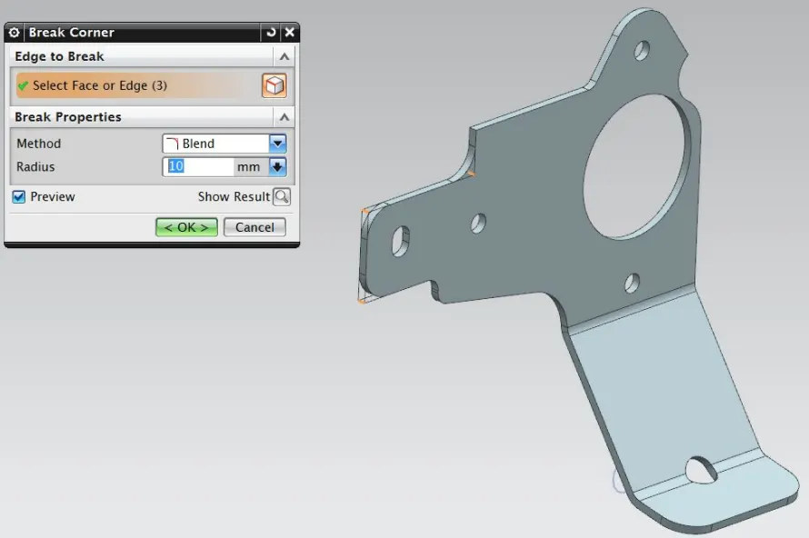
The break corner command is used to round the sharp edges of the sheet metal.
9) Advance Flange
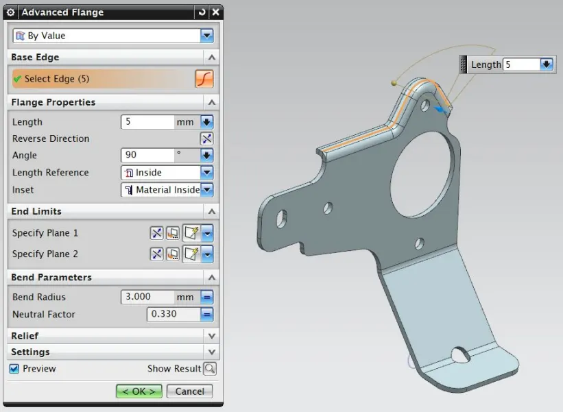
The advance flange command creates the flange along with the curved edge with perticular bend angle and flange length.
10) Unbend
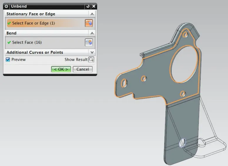
the unbend command is used to make the flanges flat w.r.t. the base feature.
11) Hole
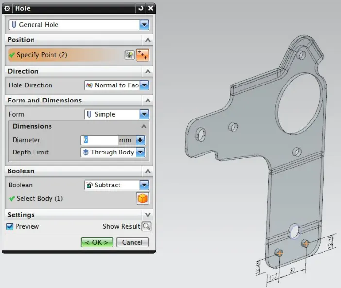
The points are provided on required positions by creating the sketch and the holes are generated using these points by hole command.
12) Normal Cutout
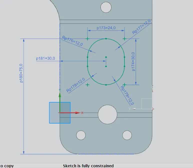
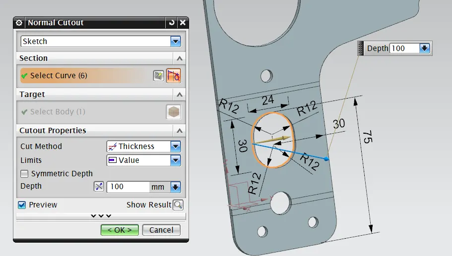
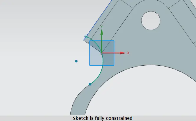
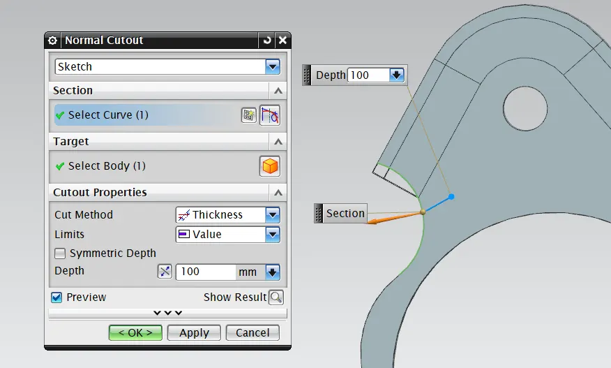
The normal cutout is used to provide the cut on the sheet metal of required sketch profile and this cut always makes 90 deg angle with the sheet metal irrespective of it's own angle with the sheet metal.
13) Advance Flange
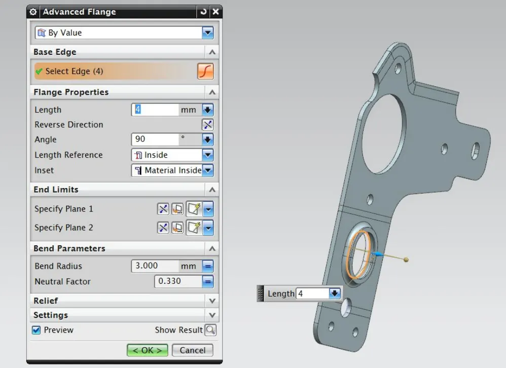
The advance flange command creates the flange along with the curved edge with perticular bend angle and flange length.
14) Rebend
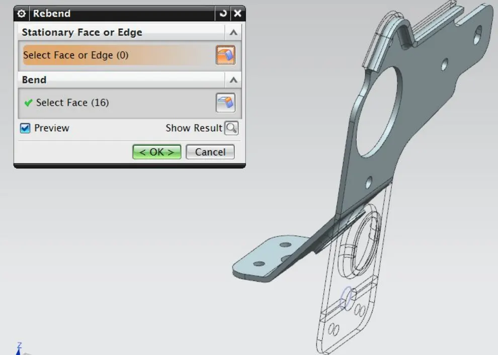
Using rebend command the sheet metal component gets it's bended form back.
15) Gusset
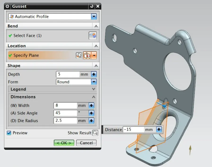
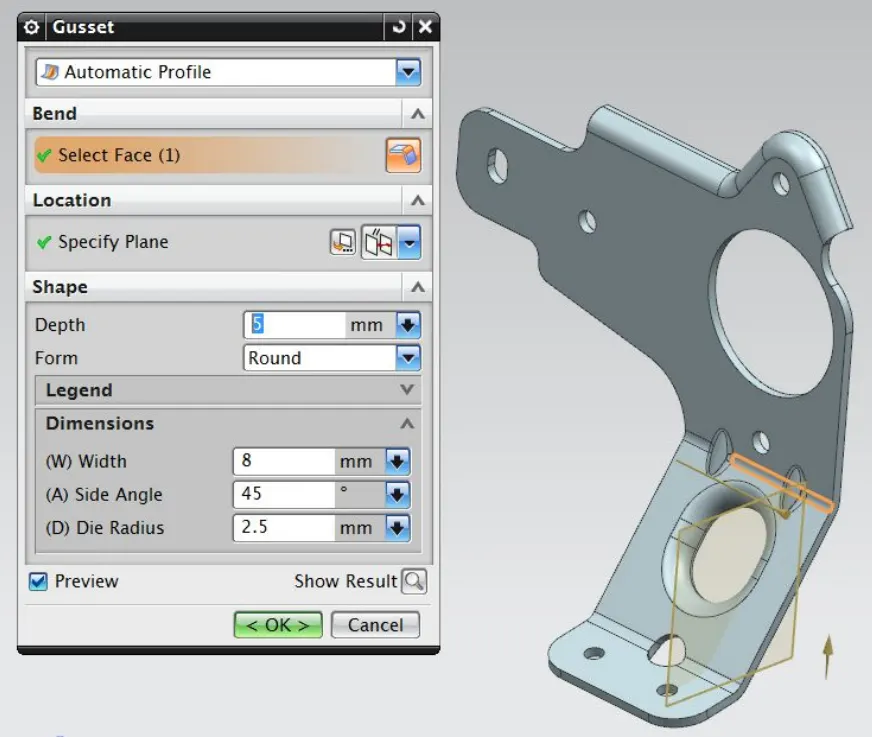
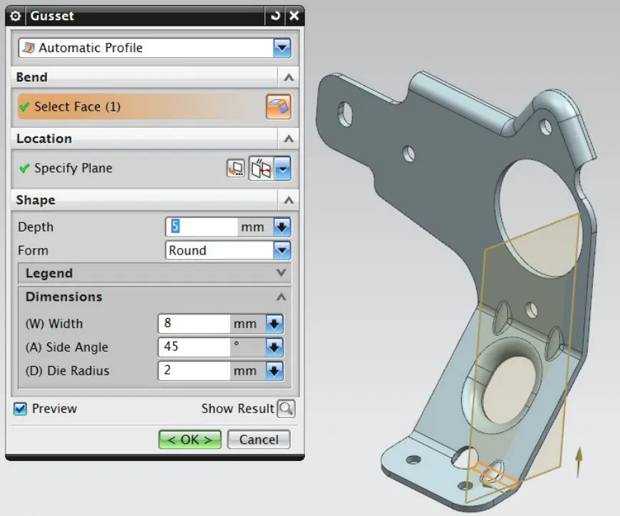
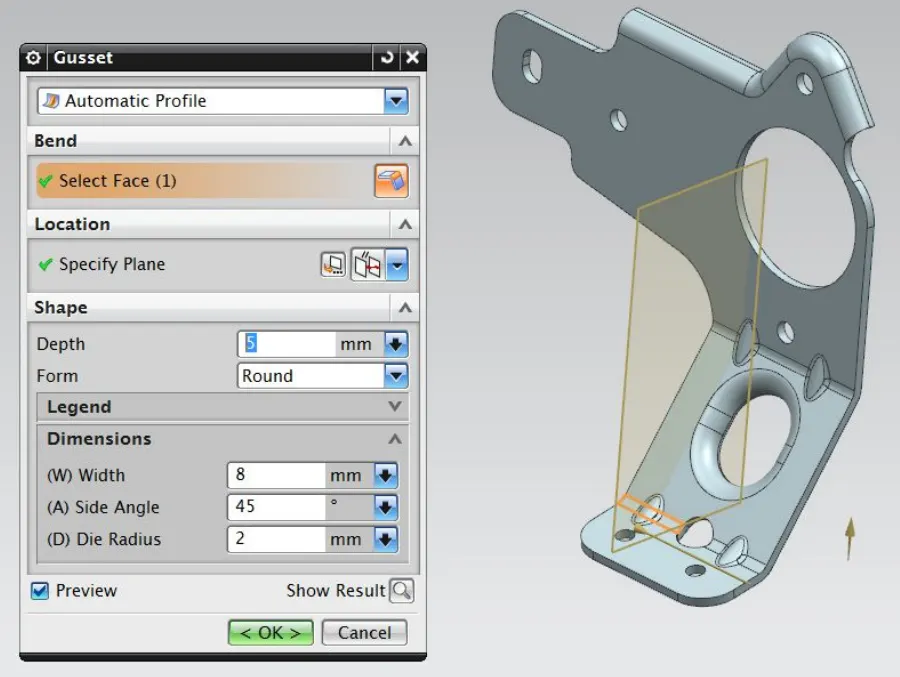
Gusset command creates the stiffening gusset on the bend edge with required dimensions and profile.
Screenshots Of The Part:
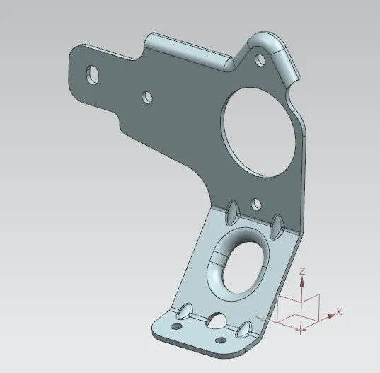
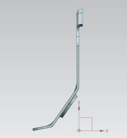
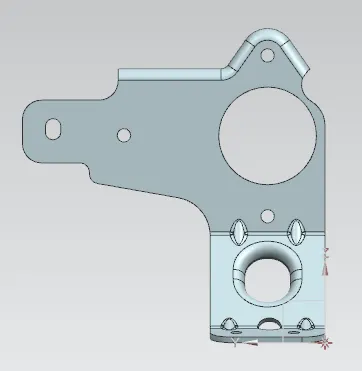
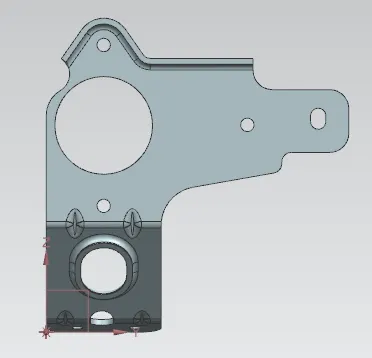
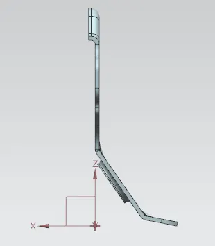
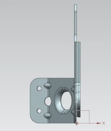
Conclusion:
In this way the bracket design has been completed using NX sheet metal application by following the given guidelines.