Roof Design
A report on 'Roof Design' of a passenger car
Objective :
- To design and model Front roof rail, Rear roof rail, Centre roof rail, Bow roofs and their assembly for the given skin part of the roof using NX12.
- Roof curvature study for :
1) Heat destortion criteria
2) Snow load criteria
- Draft analysis of roof rails
Roof :
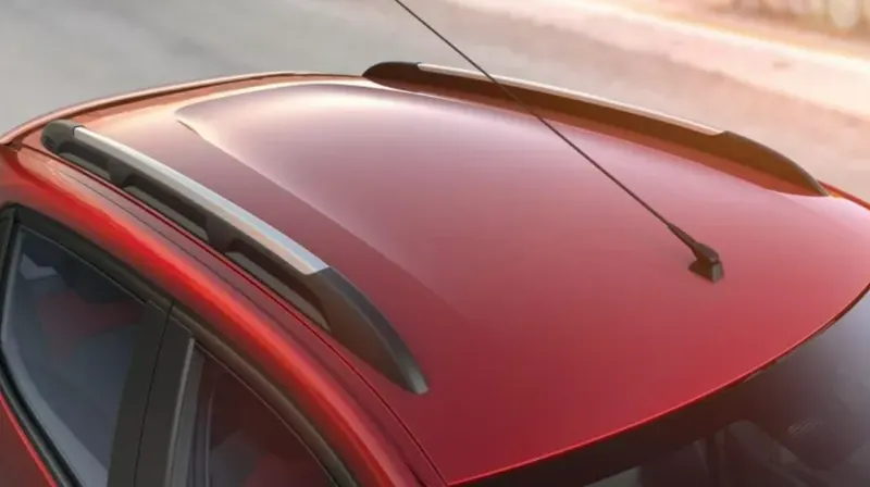
- A roof is one of the structural member of a car that covers the passenger's cabin from top and protects the cabin and passengers inside from the outer environment.
- It also provides safety to the passengers when the vehicle is subjected to crash situations like rolling and crash impact from top.
- The roof must have necessary structural properties that would help it to withstand different weather conditions, to maintain rigidity over a period of time, to sustain side roof crash etc.
- For that the roof is made up of number of components and all these are assembled together by permanent joints.
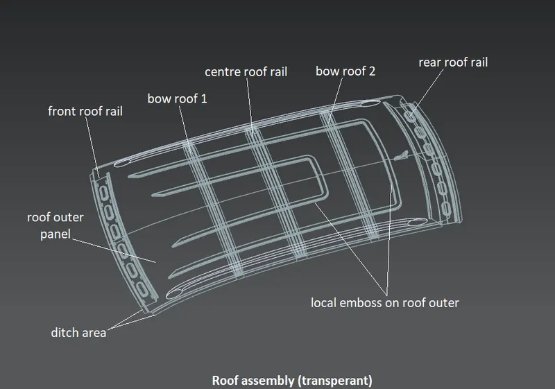
- The roof assembly consists of outer styling sheet, front roof rail, rear roof rail, reinforcement roof centre and bow roofs.
- The roof rails gives additional support and strength to the roof sheet at different sections to avoid structural failure.
- These all are joined together by joiing processes like spot welding, mastic glue and laser brazing etc.
Roof assembly and it's components:
Design steps and design considerations in roof design:
1) Given styling surface:
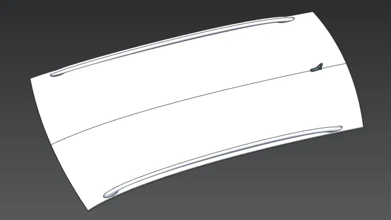
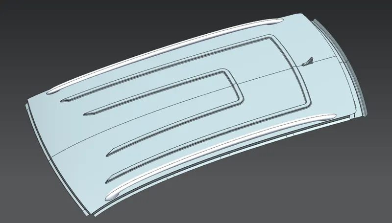
- The styling surface given by the OEM from which the offset surfaces will be created for the design of roof rails and ditch area will be design around it.
2) Ditch area and its's design considerations:
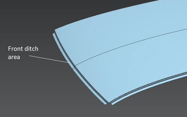
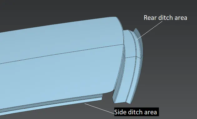
- Ditch area is the one within which flanges are designed around the outer edges of the roof to joine the roof with the roof rails as well as with bodyside outer.
- While designing ditch area all the dimensions like flange angles, flange lengths are given by considering the front and rear visibility criteria as well as the head room clearance because the positions of all roof reinforcements, head liner and the windshield glass are depends on the ditch area. The rear ditch area is designed considering the back door opening and closing. All flanges of ditch area must have positive draft to get drawn by deep drawing process.
3) Front roof rail and it's design considerations:
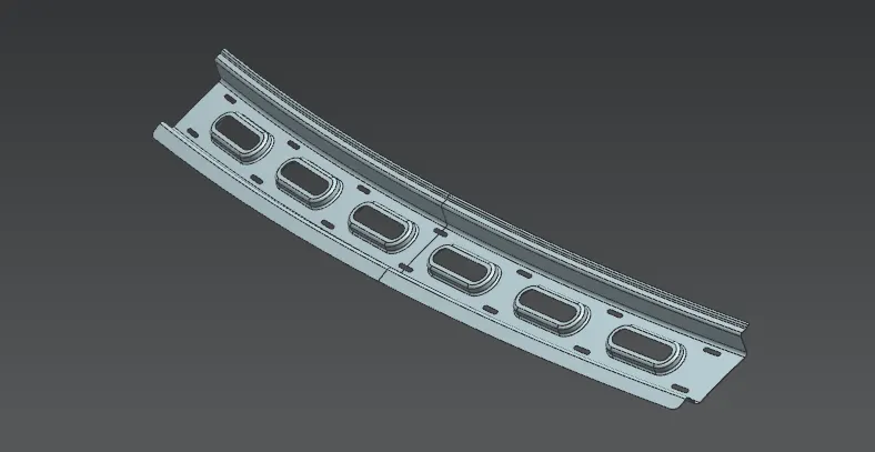
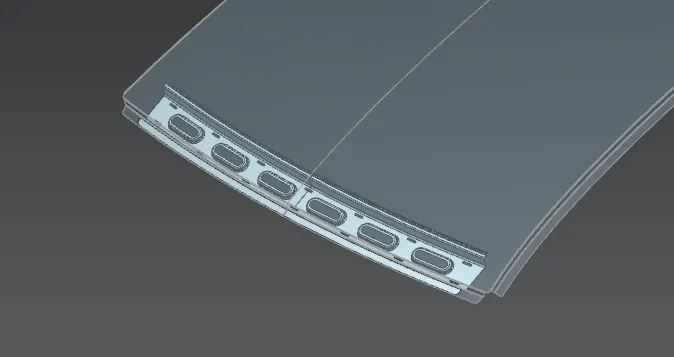
- The front roof rail is positioned at front of the roof and it's function is to support the windshield glass and to give additional strength to frontal portion of the roof. It also support some other commodities like bracket map lamp and room lamp.
- The offset distance of outer most surface of the front roof rail from the roof is set above the visibility criteria line to fulfill the front visibility criteria and width of front roof rail is given as 75-80mm for head room clearance. Also it should have positive draft to get drawn by the deep drawing.
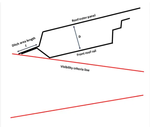
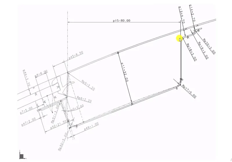
- The clearance between the roof and mastic region should be 5mm and there should be no gap between ditch area flange and front flange of roof rail for the spot welding.
4) Rear roof rail and it's design considerations:
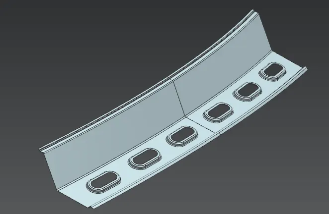
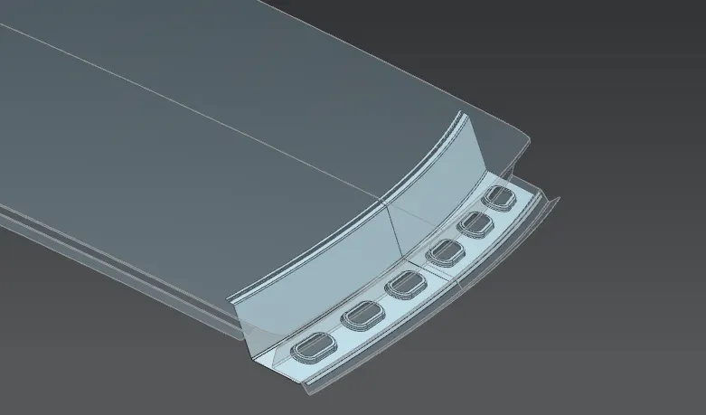
- The rear roof rail is positioned at rear of the roof and it's function is strenghten the rear portion of the roof and back door mounting.
- While designing the rear roof rail, again the rear visibility criteria and the head room clearance took under consideration according to the rear visibility criteria line.
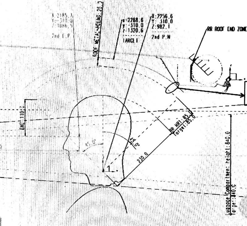
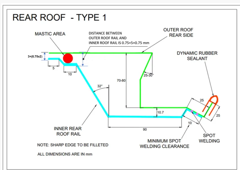
- The clearance between the roof and mastic region should be 5mm and there should be no gap between ditch area flange and rear flange of roof rail for the spot welding. For deep drawing the draft should be positive.
5) Centre roof rail and it's design considerations:

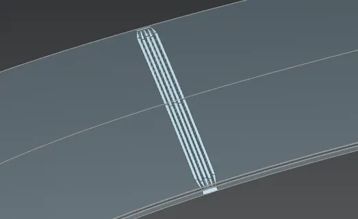
- The centre roof rail is positioned at the centre of the roof and it's function is to provide additional support and strength to middle portion of the roof. Also it holds bracket map lamp and room lamp and in some of the vehicles like station wagon, centre roof rail holds the AC vents on the top.
- The centre roof rail design must follow the head room clearance criteria and rear visibility criteria.
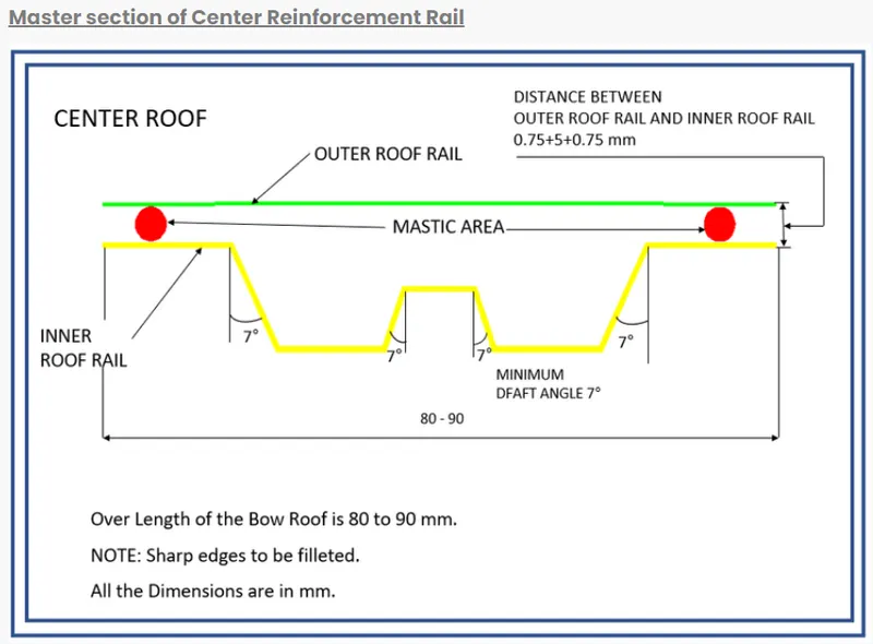
- The clearance for mastic should be 5mm for mastic region and for spot weld region there should be no gap between ditch area flange and the roof rail. The draft must be popsitive for deep drawing process for that draft angles should be greater than 7deg.
6) Bow roof 1 & 2 and their design considerations:
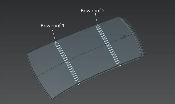
- Bow roof rail is the one which is joined to the roof where the roof has more flat curvature. If the roof has flat portion, then it is weak and may cause structural failure. The bow roof also has similar design considerations as that of centre roof rail but the most important thing is the positioning of the bow roof in the gap between FR roof rail and CTR roof rail and the gap between CTR roof rail and RR roof rail.
- For that there is Roof Curvature Study that determines whether the bow roof positions are correct or not.
Roof Curvature Study:
1) Heat destortion criteria
2) Snow load criteria
Heat destortion criteria:
- Heat destortion study determines the heat destortion temperature at which the material starts soften when it is subjected to fix load which results in structural failure of the roof. Heat destortion calculation gives the judgment condition values for the bow roof position to withstand this situation.
- Formula:
W = [1.73 x 10^(-3) x L] + [1.85 x 10^(-8) x (R^2)/t] + [ 1.10x10^(-3) x l] - 2.68
Where,
L = Roof Length in X-Direction[mm](Roof dimension in 0-Y)
R = Roof curvature
R = 2(Rx*Ry)/(Rx+Ry)
Rx = X curvature
Ry = Y curvature
t = Roof plate thickness [mm]
l = Bow Roof Span [mm]
Judgement Condition : OK W< 2.7
- Results:
-
Roof Rail Positions Rx Ry R l L t R2/t W OK/NG FR & 1st 5697.68 2979.32 3912.69 512.12 2027.68 0.75 20408330 1.76 OK 1st & CTR 4808.85 6854 5652.11 311.39 2027.68 0.75 42595129 1.95 OK CTR & 2nd 3977.66 10580.21 5781.68 379.89 2027.68 0.75 44570431 2.07 OK 2nd & RR 3294.29 14495.43 5368.51 377.40 2027.68 0.75 38427866 1.95 OK
Snow load criteria:
- In winter season heavy snowfall occures in some regions. During these kind of situations snow occumulates on the roof of the vehicle in large volume which causes bending of the roof. In order to limit this bending upto certain amount and let the roof ratain it's original shape after removal of snow, the appropriate positioning of the bow roof is very important.
- The following snow load calculations gives judgment condition values for bow roof positioning to ensure enough sustainability of the roof for this situation.
- Formula: Qr =[Iy x t^2] / [α x s x [(Rx + Ry)/2]^2 x 10^-8]
Where,
α = My x Lx^2 x 10^-12 , My = Y(Ly-Y)
t = Roof plate thickness [mm]
Ly = Distance between the front and rear roof Rails on the Vehicle along with 0Y[mm]
Length of Roof panel with the center point between Roof rail Front /Rear as the reference point of the front and the rear.
Lx= Distance between the Left and Right end of the roof on the Roof BOW [mm]
Width of the roof panel exposed on the surface.
Y = Distance front Front Roof Rail to Roof BOW[mm]
s= Distance for which Roof BOW bears divided load [mm]
s = L1/2 + L2/2
Iy = Geometrical moment of inertia of Roof BOW (Y cross-section )[mm4]
Rx = Lateral direction curvature radius of roof panel Y cross-section on Roof BOW [mm]
Roof panel curvature Radius of the Length Lx in Front view
Ry = Longitudinal Direction curvature radius of the Roof panel X cross-section on Roof BOW [mm]
Judgement condition = Qr ≥ 3.1
250 ≤ s ≤ 380
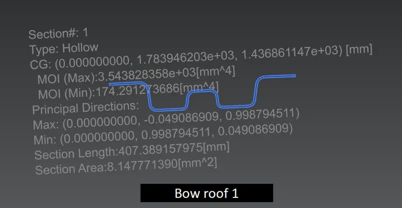
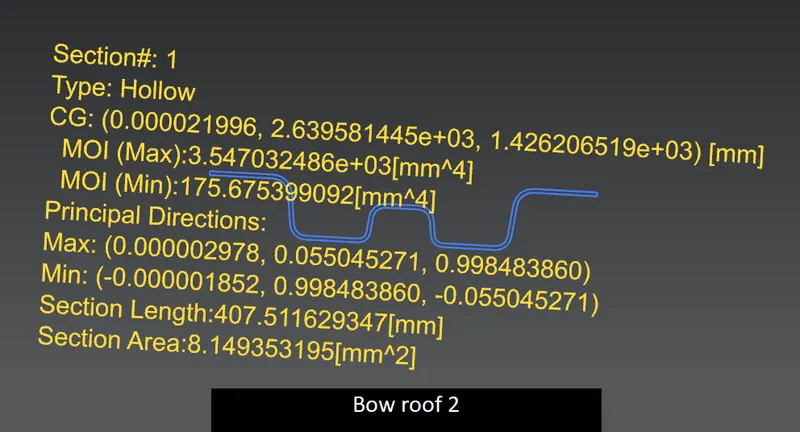
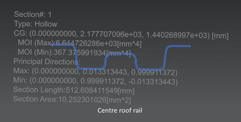
- Momemt of inertia of the bow roofs:
- Results:
-
Roof rail positions Iy α Lx Ly Y s Rx Ry t Qr OK/NG FR & 1st 174.29 1.04 1100.56 2031.46 606.85 500.13 4292.74 2985.17 0.75 1.42 NG 1st & CTR 367.37 1.18 1073.35 2031.46 997.69 428.17 3808.46 6780.45 0.75 1.45 NG CTR & 2nd 175.67 0.93 1054.26 2031.46 1456.98 480.91 4274.28 11063.12 0.75 0.38 NG
- From above results all three Qr values doesn't satisfy the judjment condition value. To compensate this issue, local embosses are introduced on the roof outer panel to withstand against snow load.
Draft Analysis:
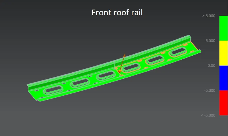
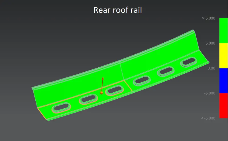
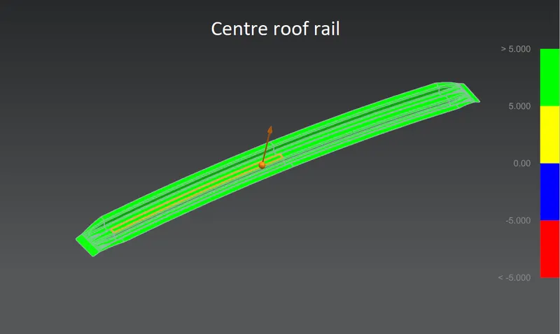
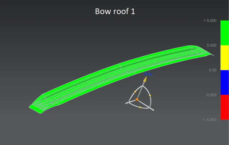
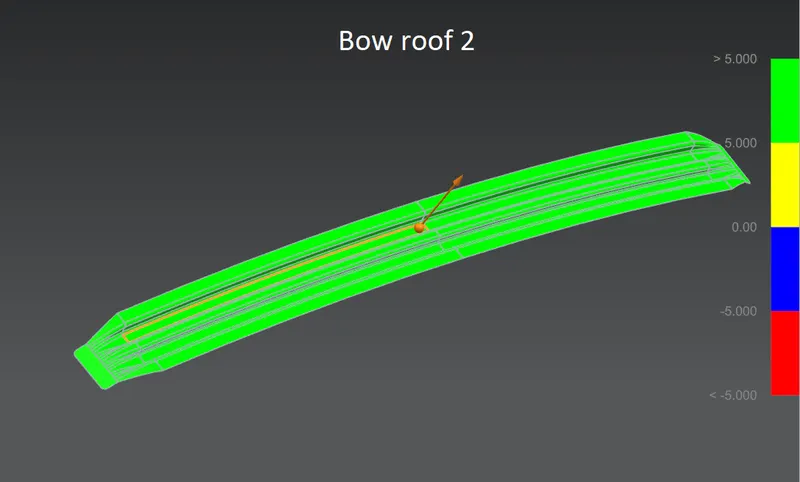
- Draft analysis is been done on each component of the roof assembly to check whether the draft is positive or negative.
- If there is a negative draft on any ragion of the component, the component might face structural damage issues also it afffects the product life cycle of the deep drawing tool.
Manufacturing Processes:
1) Forming process -
a) Deep drawing
b) Stamping
2) Joining Process -
a) Spot welding
b) Mastic glue joining
c) Laser brazing
Deep drawing:
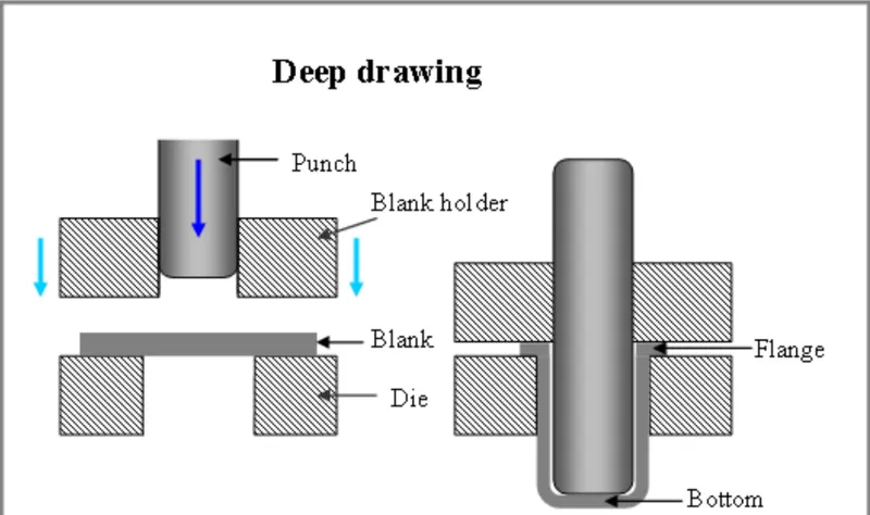
- Deep drawing is the most common metal forming process used to form the metal sheets in different shapes. The shape is given to the blank(sheet metal) by holding it above the die and the punch gradually forced the blank into the die to get required shape.
Stamping:
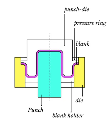
- The process of turning sheets of metal into a useful part or component is called sheet metal stamping. The metal is fed into a press, where the stamping tool, also known as a die, creates the desired shape. The die is pressed into or through the metal with tremendous force.
Spot welding:
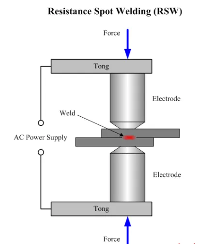
- Spot welding is a resistance welding process used primarily to weld two or more metal sheets together. It is achieved by applying pressure and electric current to the spot-weld area. The required heat is generated by the metal’s internal resistance to the electric current.
- The electric current and pressure are applied by copper alloy electrodes whose tips are placed on the opposite sides of the metal pieces. The generated heat melts the metal while the pressure from the electrodes squeezes the molten metal to form a weld.
- It’s called spot welding because this welding method creates a tiny dot weld, that looks like a spot. The weld created between the copper electrodes is also sometimes called a nugget.
Mastic glue joining:
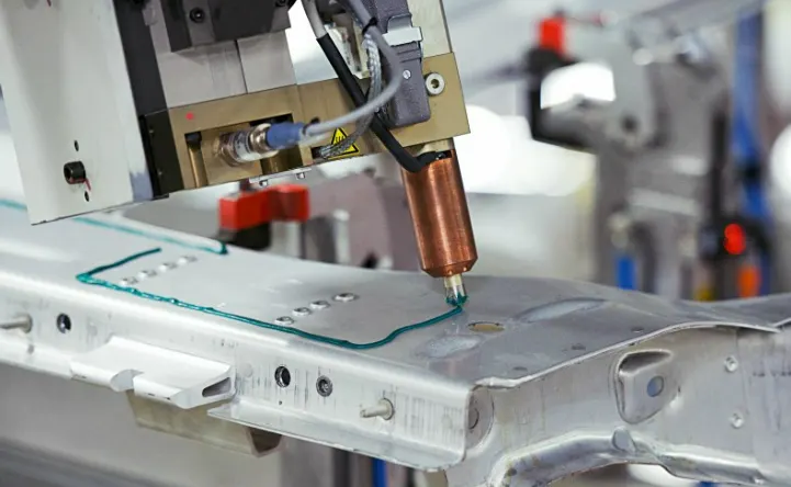
- In mastic joining process, the mastic glue is applied to the mastic(joining) region of the sheet metals and 5mm clearance is left between the sheets to be joined. After application of heat the mastic expands 5mm radially outward and make permanant adhesive bond between two metal sheets.
Laser brazing:
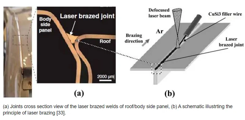
- Laser brazing is a thermal joining process in which, a filler metal is placed at or between the faying surfaces of the metals to be joined and heat is applied using a laser beam to melt the filler material, but not the parent metals.
- Brazing allows for a tighter bond in comparison to welding or soldering. The molten filler metal bonds with the base metal to form a strong, sealed joint.