Week 12- Final project
A Design Report On 'Door Trim Panel Assembly'
Objective:
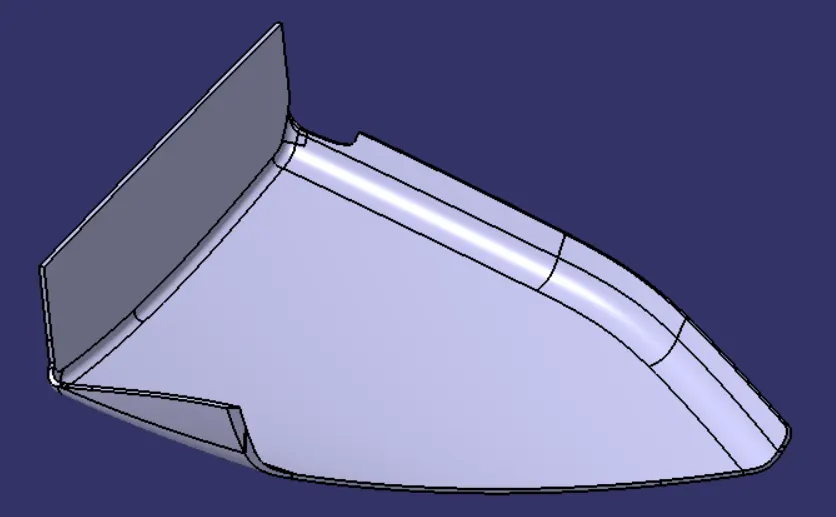
To design solid bodies of door trim panels from given class-A surface, design and develope B-surface engineering features like heat stakes, locators, doghouse, ribs, attachement flanges using given master-section. Perform draft analysis on each panel.
Introduction:
The automotive industry is on the brink of a revolution, and the plastics industry poised to play a major role. The real plastics revolution in automotive industry began in 1950 when thermoplastics made their debut, starting with ABS and going on to polyamide, polyacetal and polycarbonate together with introduction of alloys and blends of various polymers. The ongoing development of advanced, high-performance polymers has dramatically increased their usage. Originally plastics were specified because they offered good mechanical properties combined with excellent appearance, including the possibility of self-coloring. The application of plastic components in the automotive industry has been increasing over the last decades. Nowadays, the plastics are used mainly to make cars more energy efficient by reducing weight, together with providing durability, corrosion resistance, toughness, design flexibility, resiliency and high performance at low cost.
Plastics In Automotive:
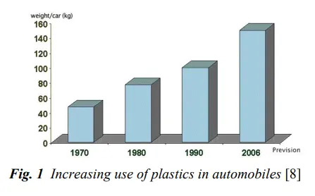
The average vehicle uses about 150 kg of plastics and plastic composites versus 1163 kg of iron and steel – currently it is moving around 10-15 % of total weight of the car (Fig. 1).
 During the enormous growth of plastics components in automotives, the advantages of using plastics have changed. Mounting costs are being met by the ability of plastics to be molded into components of complex geometries, often replacing several parts in other materials, and offering integral fitments that all add up to easier assembly. Many types of polymers are used in more than thousand different parts of all shapes and sizes. A quick look inside any model of the car shows that plastics are now used in exterior and interior components such as bumpers, doors, safety and windows, headlight and side view mirror housing, trunk lids, hoods, grilles and wheel covers.
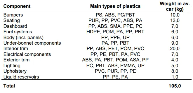
Although up to 13 different polymers may be used in a single car model (Fig. 3), just three types of plastics make up some 66 % of the total plastics used in a car: polypropylene (32 %), polyurethane (17 %) and PVC (16 %).
1)Polypropylene(PP):
polypropylene is extremely chemically resistant and almost completely impervious to water. Black has the best UV resistance and is increasingly used in the construction industry. Application: automotive bumpers, chemical tanks, cable insulation, battery boxes, bottles, petrol cans, indoor and outdoor carpets, carpet fibers.
2)Polyurethane(PUR):
polyurethane materials are widely used in high resiliency flexible foam seating, rigid foam insulation panels, microcellular foam seals and gaskets, durable elastomeric wheels and tires, automotive suspension bushings, electrical potting compounds, hard plastic parts (such as for electronic instruments), cushions.
3)Poly-Vinyl-Chloride(PVC):
poly-vinyl-chloride has good resistance to chemical and solvent attack. Its vinyl content gives it good tensile strength and some grades are flexible. Colored or clear material is available. Application: automobile instruments panels, sheathing of electrical cables, pipes, doors, waterproof clothing, chemical tanks.
4)Acrylonitrile-Butadiene-Styrene(ABS):
acrylonitrile-butadiene-styrene is a durable thermoplastic, resistant to weather and some chemicals, popular for vacuum formed components. It is a rigid plastic with rubber like characteristics, which gives it good impact resistance. Application: car dashboards, covers.
5)Polyamide(PA):
polyamide is known as nylon 6.6 or nylon 6. Both these nylons have high resistance to abrasion, low friction characteristics and good chemical resistance. They also absorb water easily and components in wet or humid conditions will expand, precluding their use in applications where dimensional stability is required. Application: gears, bushes, cams, bearings, weather proof coatings.
6)Polystyrene(PS):
polystyrene is very popular, ease to manufacture, but has poor resistance to UV light. Application: equipments housings, buttons, car fittings, display bases.
7)Polyethylene(PE):
polyethylene has good chemical resistance. Two types are used, low density polyethylene (LDPE) and high density polyethylene (HDPE) can be manufactured in a range 30 of densities. Application: glass reinforced for car bodies, electrical insulation, packaging, where strength and aesthetics are important.
8)Polyoxymethylene(POM):
polyoxymethylene (also know as polyacetal or polyformaldehyde) has big stiffness, rigidity and excellent yield, which are stable in low temperatures as well. Very good chemical and fuel resistance. Application: interior and exterior trims, fuel systems, small gears.
9)Polycarbonate(PC):
polycarbonate has good weather and UV resistance, with transparency levels almost good as acrylic. Applications: security screens, aircraft panels, bumpers, spectacle lenses, headlamp lenses.
10)PMMA:
acrylic is more transparent than glass, has reasonable tensile strength (shatter proof grades are available) and good UV and weather resistance, high optical quality and surface finish with a huge colour range. Application: windows, displays, screens.
11)Polybutylene Terephthalate(PBT):
polybutylene terephthalate has good chemical resistance and electrical properties, hard and tough material with water absorption, very good resistance to dynamic stress, thermal and dimension stability. Easy to manufacture - fast crystallization, fast cooling. Application: foglamp housings and bezels, sun-roof front parts, locking system housings, door handles, bumpers, carburetor components.
12)polyethylene terephthalate(PET):
polyethylene terephthalate has similar conditions as PBT, good thermal stability, good electrical properties, very low water absorption, excellent surface properties. Application: wiper arm and their gear housings, headlamp retainer, engine cover, connector housings.
13)acrylonitrile styrene acrylate(ASA):
acrylonitrile styrene acrylate material has great toughness and rigidity, good chemical resistance and thermal stability, outstanding resistance to weather, aging and yellowing, and high gloss. Application: housings, profiles, interior parts and outdoor applications.
Manufacturing Process:
Injection Moulding:
Injection moulding is one of the most commonly used production processes for plastics. It offers a viable solution for the mass production of high-quality injection automotive parts from a broad range of polymers. In the automotive industry, where consistency, safety, and quality are of utmost importance, automotive plastic injection moulding is an important manufacturing process.
Plastic injection moulding is the process of melting plastic pellets that once malleable enough, are injected at pressure into a mould cavity, which fills and solidifies to produce the final product.
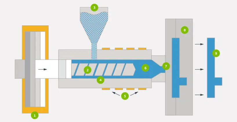
From left to right, the components of a rapid injection moulding press include ram (1), screw (2), hopper (3), barrel (4), heaters (5), materials (6), nozzle (7), mould (8), and part (9).
Door Panel Plastic Trim:
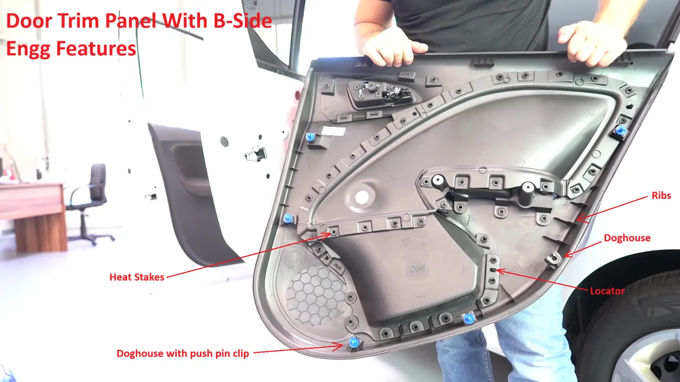
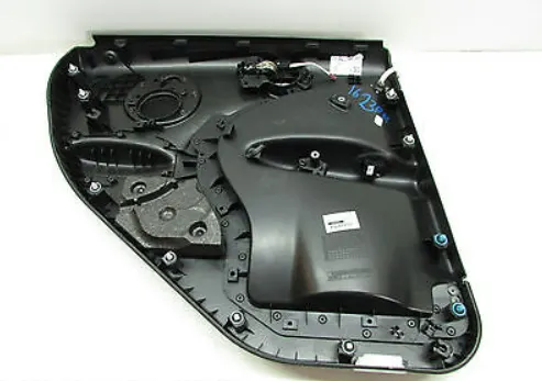
Inputs:
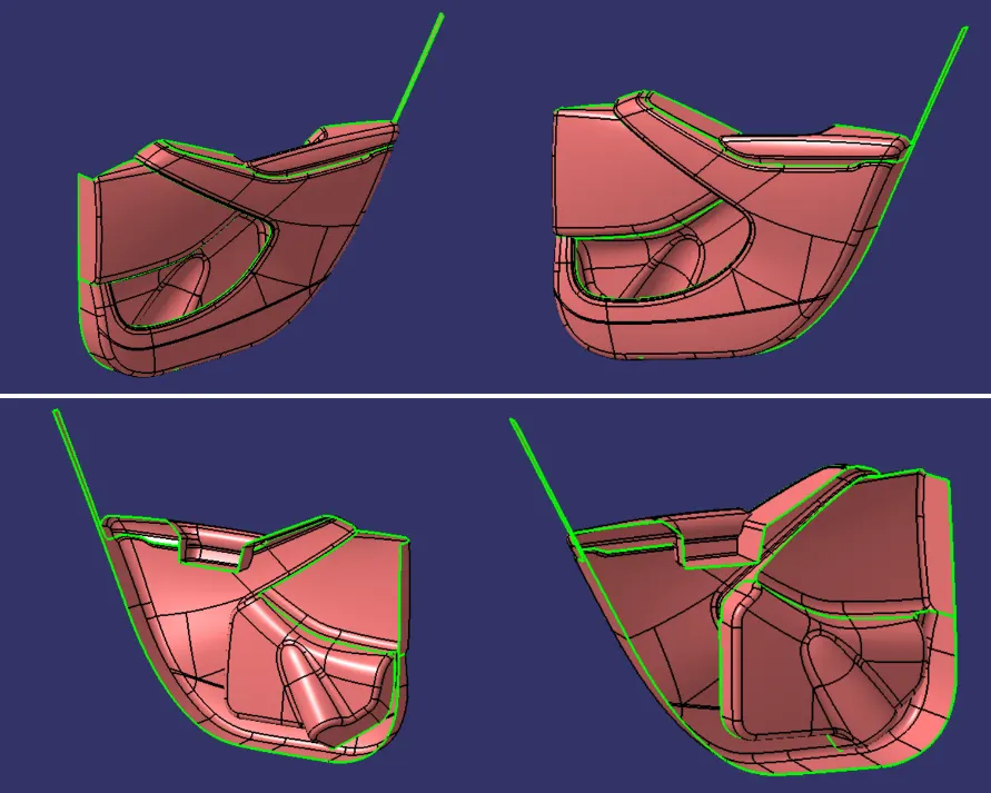
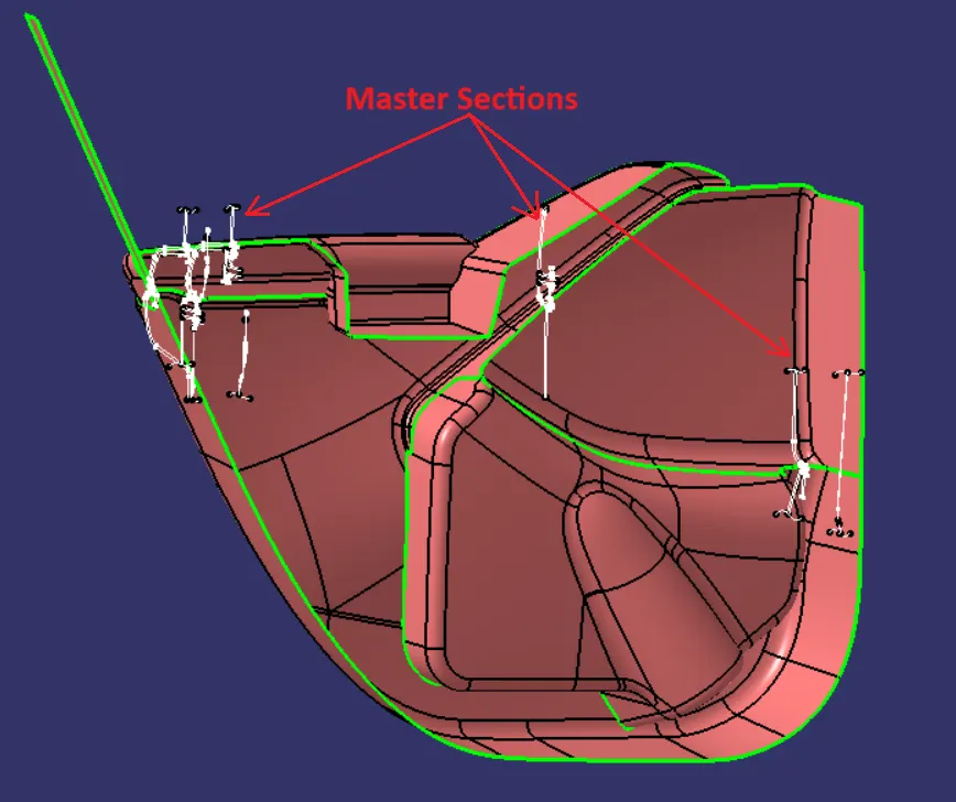
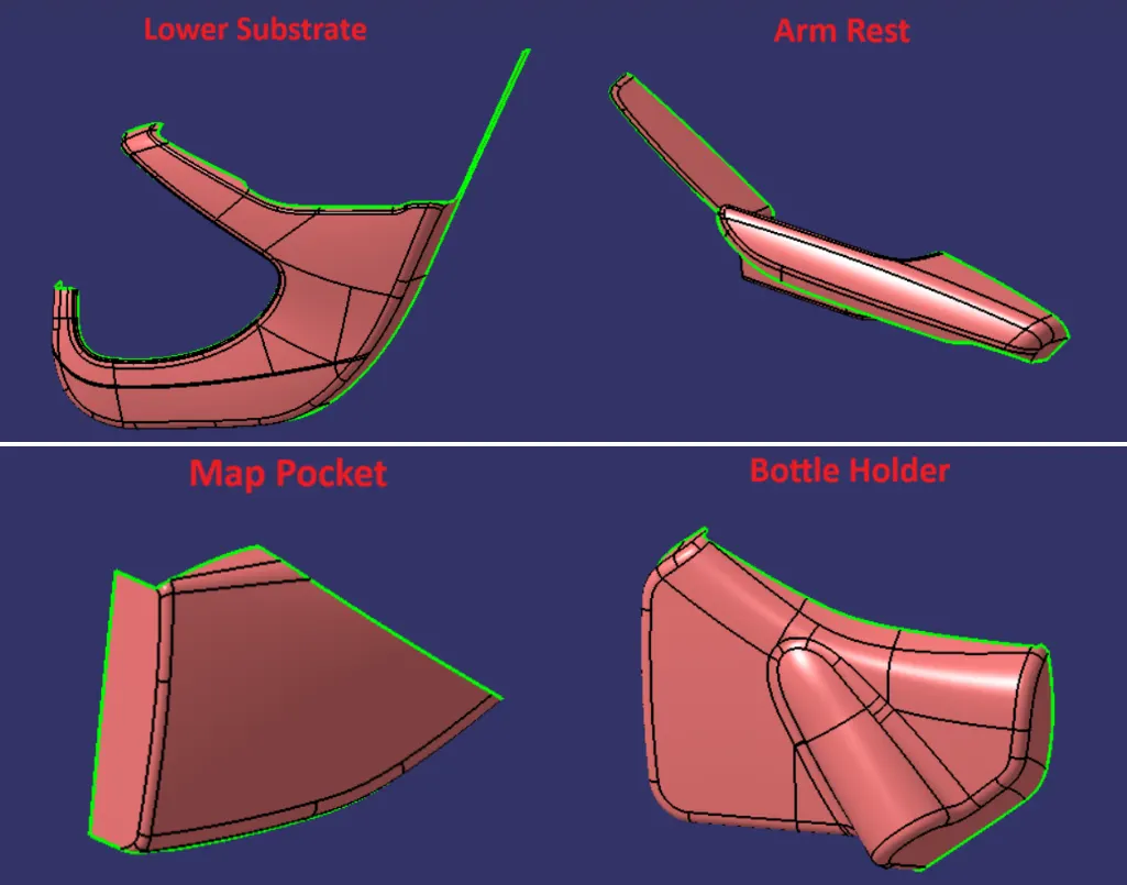
Extracetd Surfaces To Work Individually:
Draft Analysis:
- The draft analysis determines whether the part is manufacturable or not. The forming processes which uses the core and cavity to manufacture the parts, always required some draft(opening angle). Draft allows the formed part inside mold to get eject from the core and cavity.
- It helps the part to leave the mold surface in the erlier stage of ejection or mold opening. Hence reduces the friction between the part and mold which results long life of core and cavity and production of finished parts.
- Therefore while designing a cad model it is always important that the draft must be positive for convenient manufacturing. If the part has negative draft then this will affect the mold opening and part ejection, hence results in improper manufacturing process and the output part.
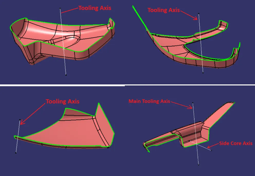
Axis Of Tooling Direction For Each Surface:
Draft Analysis Of Each Class-A surface:
1) Bottle Holder:
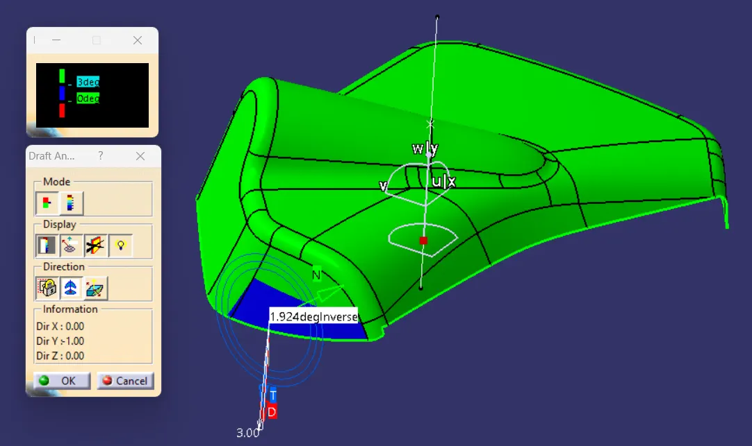
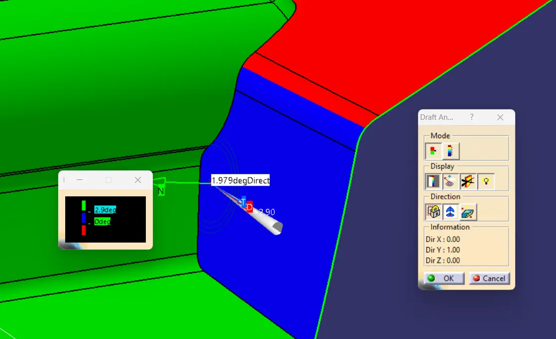
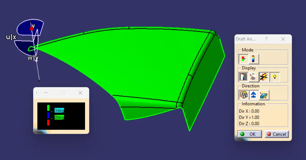
The nominal draft angle value is considered as 3 deg. which is shown on green area. The areas represented in blue colour has 0.1 & 0.5 deg minimum draft. Red coloured area has negative draft value. This is a concern with the class-A surface which doesn't follows the design rule but for the project level work it is neglected.
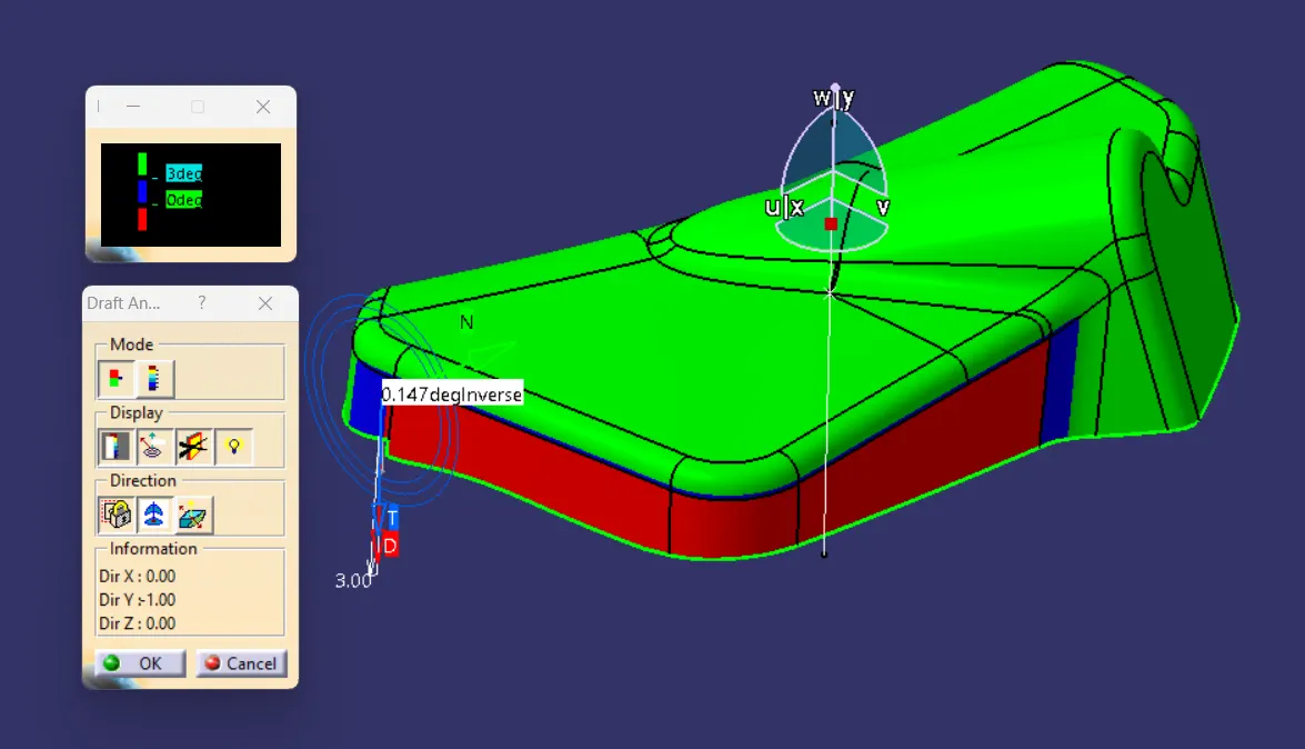
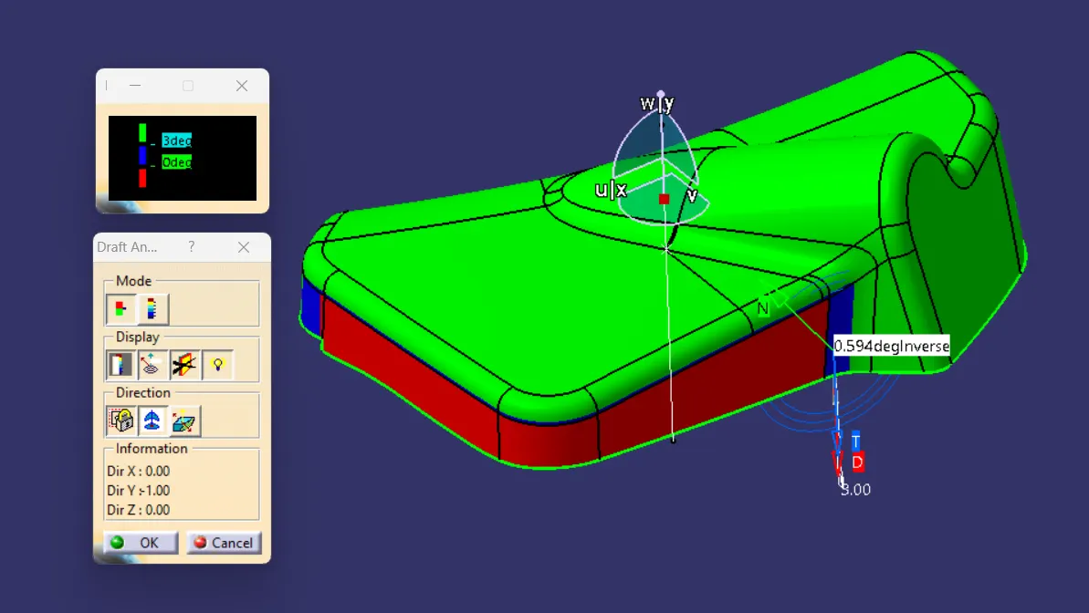
The minimum draft value on blue patch in below image is 1.9 deg.
2) Arm Rest
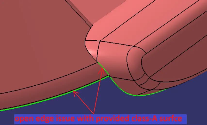
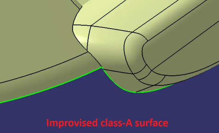
The arm rest class-A surface has to be improvise firstly due to previous open edge issues that are solved in below images.
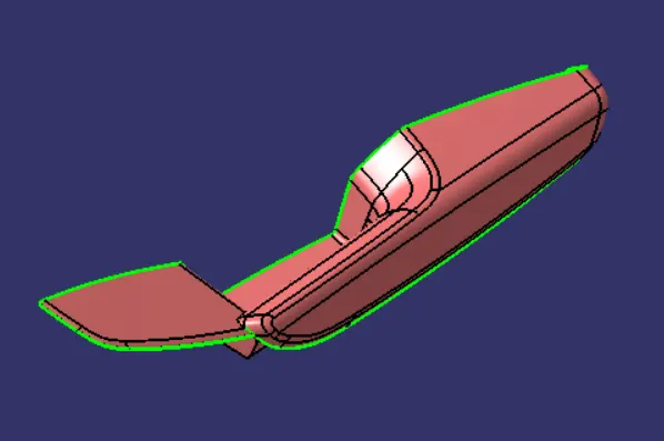
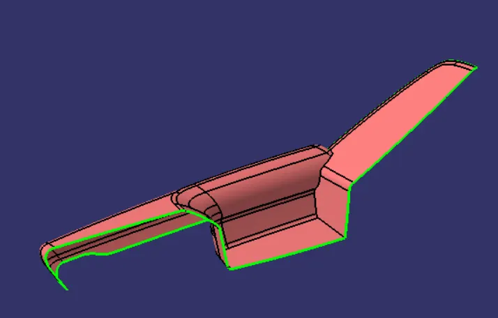
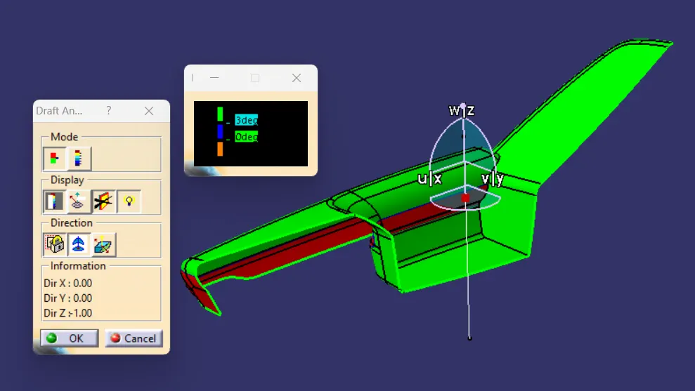
Draft analysis of arm rest surface with the main tooling direction (nominal angle is kept as 3deg.)
NOTE:
The arm rest class-A surface is originally made with two different surfaces and both the surfaces has their own tooling directions and drafts. But here we kept the surface as a single surface and perform draft analysis on it. The maximum draft results achieved are shown in below images.
The green colour area has positive draft and the patches shown in red colour has negative draft that will be cleared with the side core tooling direction.
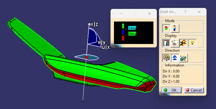
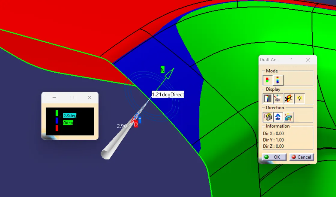
Draft analysis with side core tooling direction, the angle is kept as 3deg.
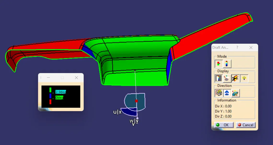
The minimum drafts on blue patches are close to 2 deg. and 1.2 deg respectively in below images.
3) Lower Substrate
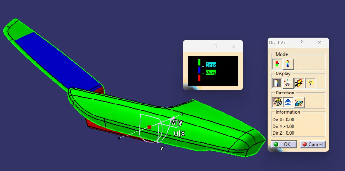
The nominal draft angle for lower substrate is kept as 3 deg and the surface has fully cleared the draft.
4) Map Pocket
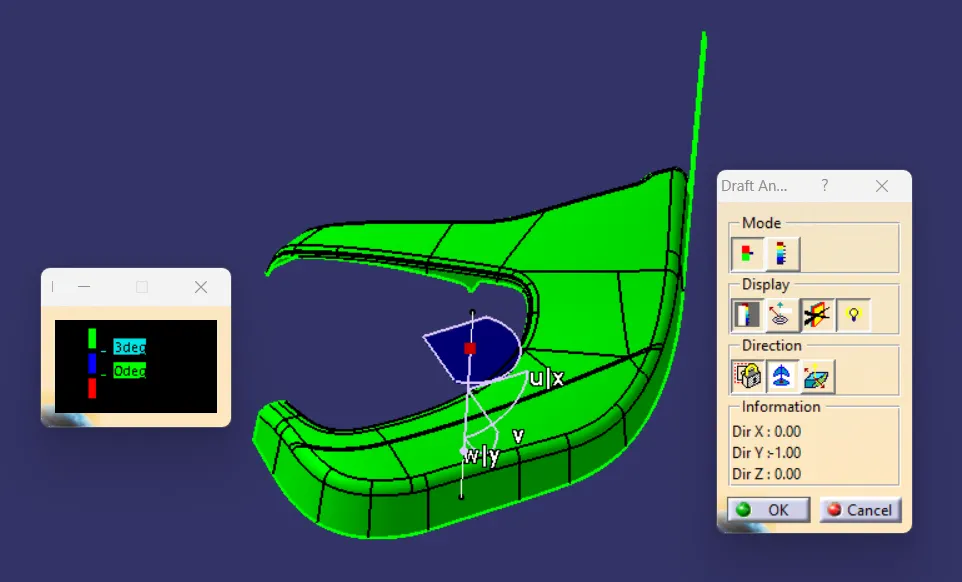
The nominal draft angle for map pocket is kept as 3 deg and the surface has fully cleared the draft.
Class-B, Class-C, Close Surface & solid body Creation:
1) Bottle Holder:
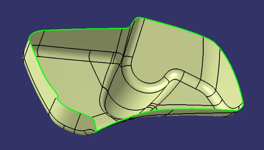
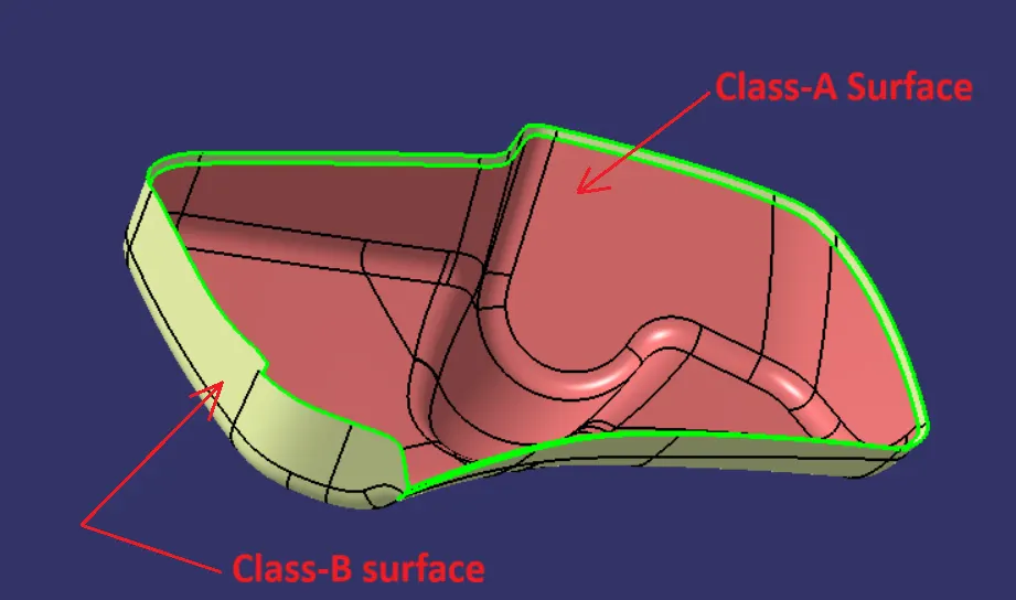
a) class-B surface -
Offseted by 2.5mm from class A surface.
b) class-C surface -
c) closed surface and final trim -
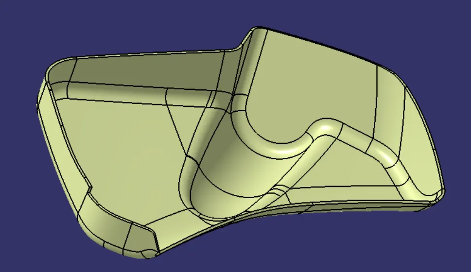
d) solid part body by close surface method -
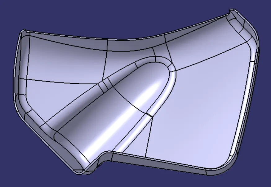
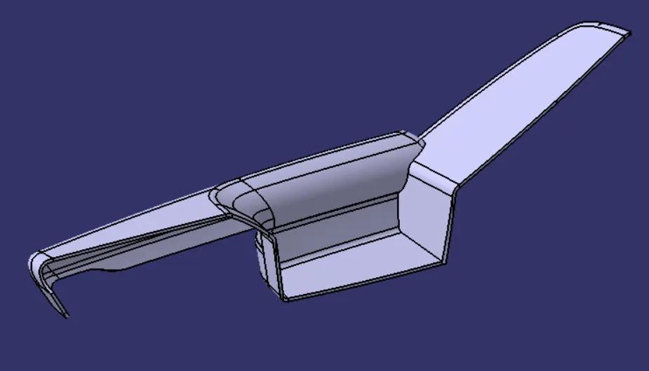
2) Arm Rest:
a) Class-B Surface -
Offseted by 2.5mm from class A surface.
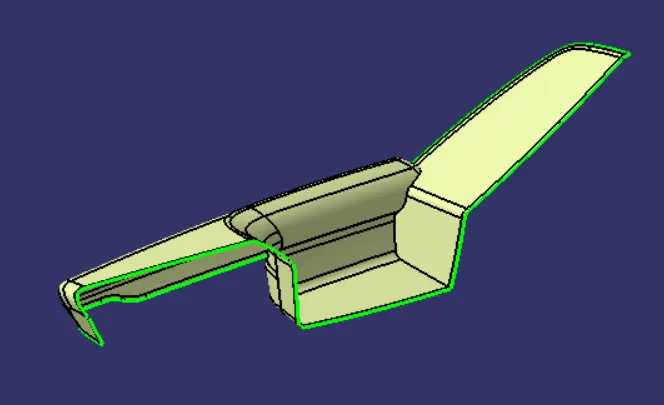
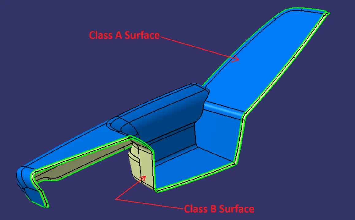
b) class-C surface -
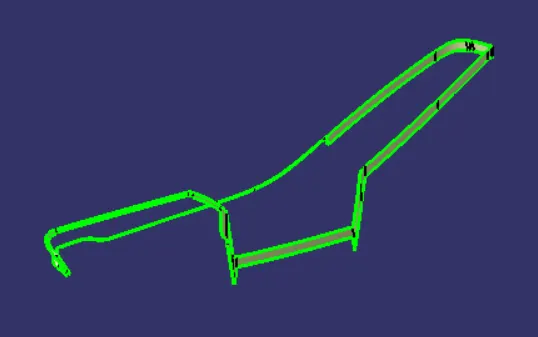
c) closed surface and final trim -
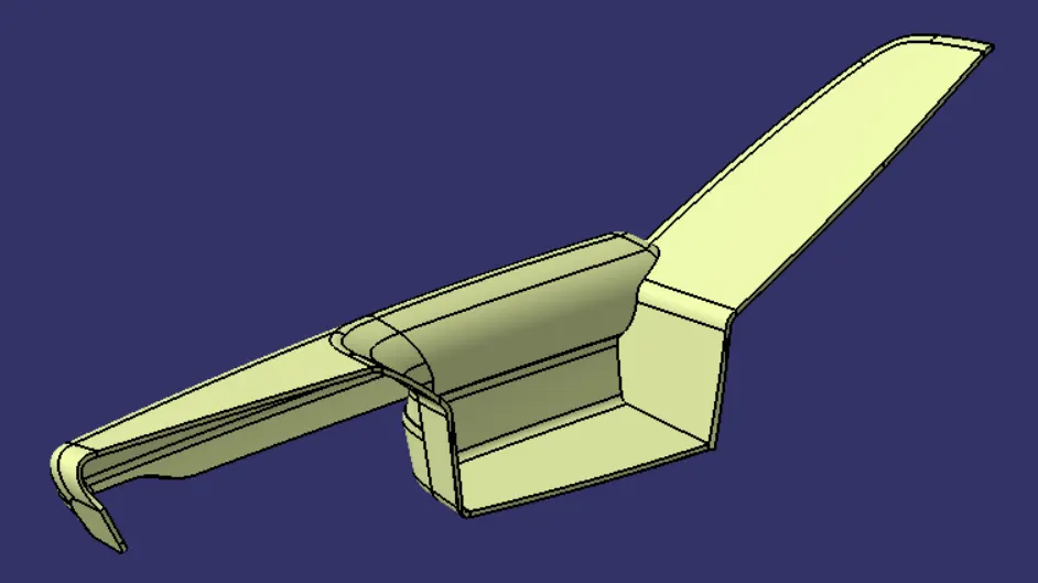
d) solid part body by close surface method -
3) Lower Substrate:
a) Class-B Surface -
Offseted by 2.5mm from class A surface.
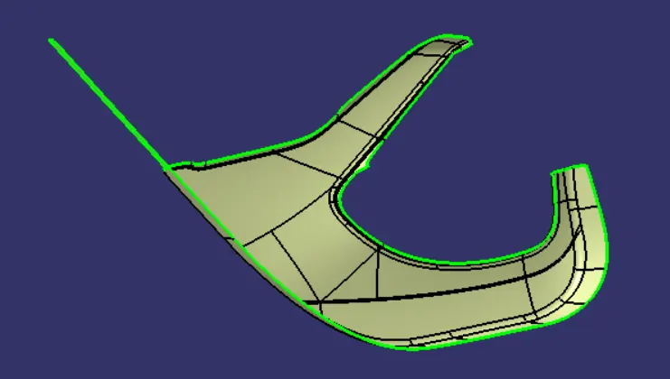
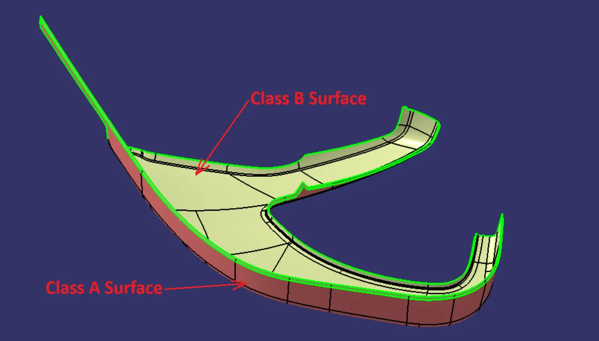
b) class-C surface -
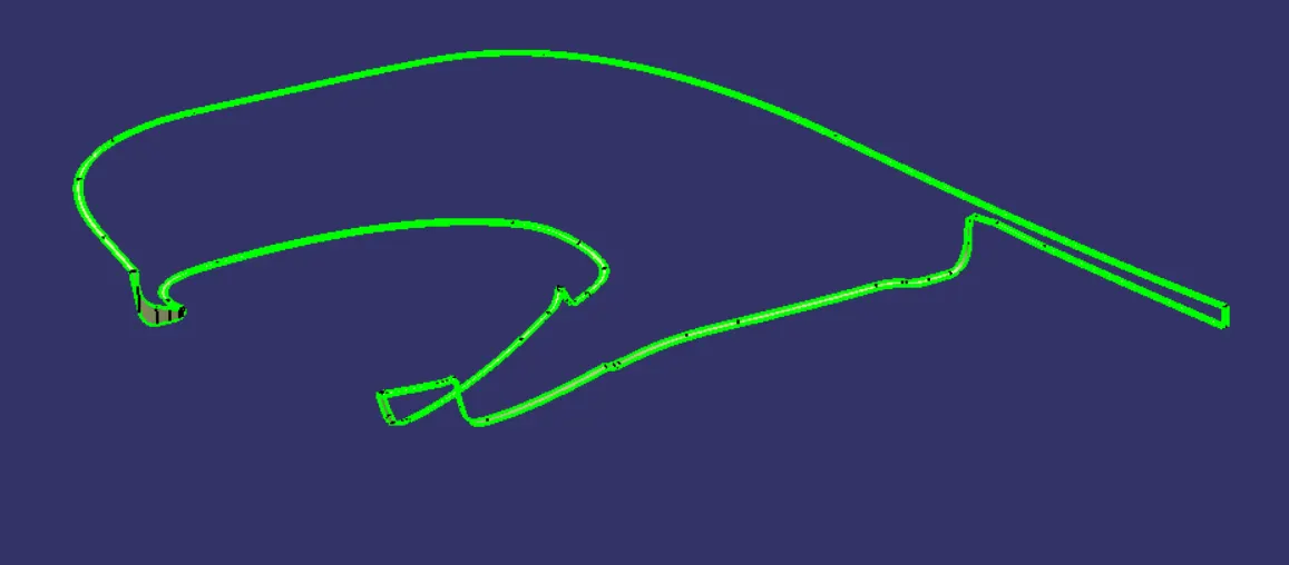
c) closed surface and final trim -
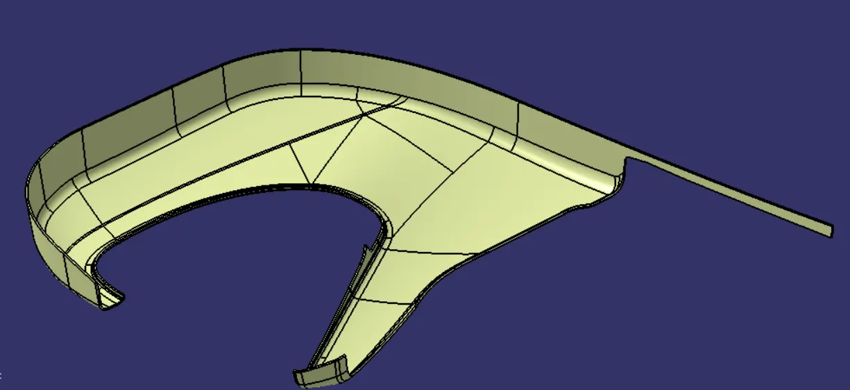
d) solid part body by close surface method -
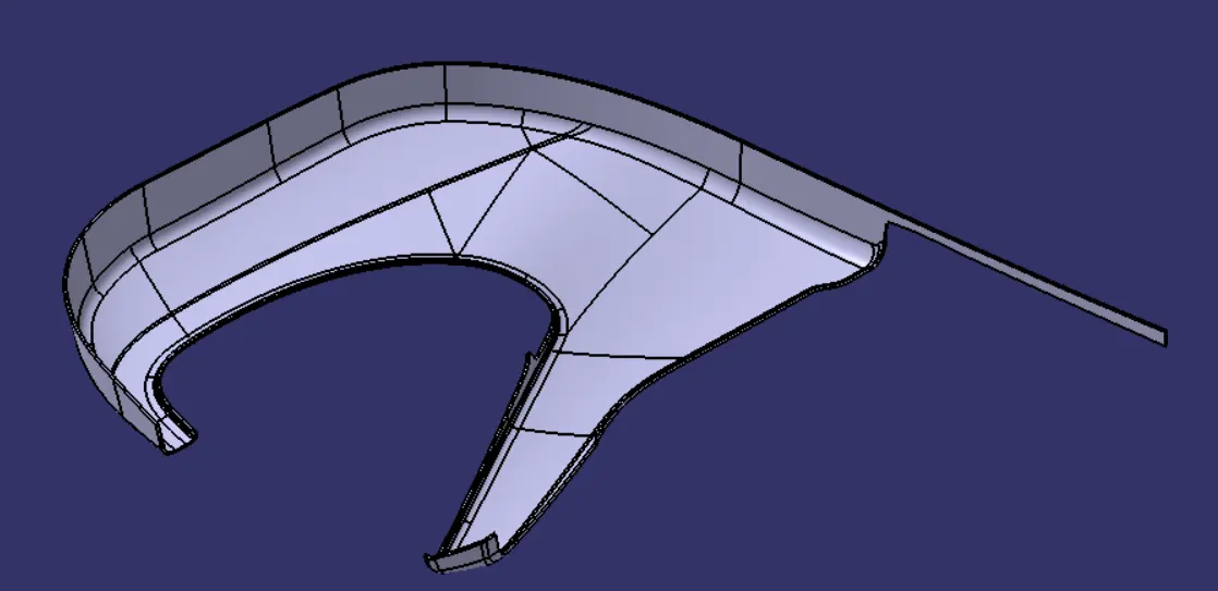
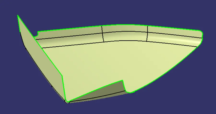
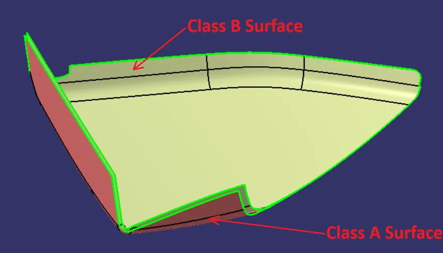
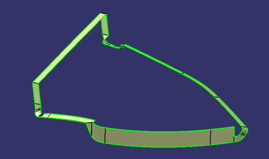
4) Map Pocket:
a) Class-B Surface -
Offseted by 2.5mm from class A surface.
b) class-C surface -
c) closed surface and final trim -
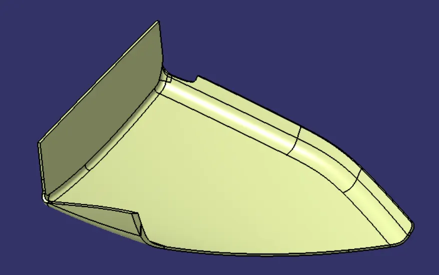
d) solid part body by close surface method -
B - Side Engineering Features Design:
1) Heat Stakes
2) Locator Pins
3) Support Ribs
4) Dog House
5) Attachment Flanges
1) Heat Stake
a) Significance of heat staking for plastic assembly:
- While multiple industrial processes for high quality plastic assembly exist, heat staking continues to earn a significant amount of market share for the sectors.
- While the industrial products of yesteryear were attached using hardware fasteners, this practice become obsolete once heat staking technology became the industry standard.
- Heat staking eleminates the need of extra hardware, which can become defective, break or otherwisw suffer from quality control issues. Additionally, hardware fasteners tend to be more expensive and labour intensive than heat staking plastic fastening options.
b) Plastic assembly with heat staking - how does it work?
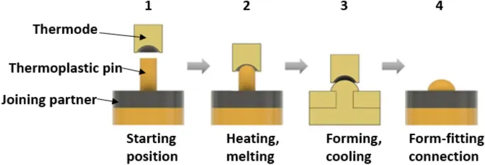
- Heat staking technology is quite simple in concept. When two or more components need to get attached to one another, and at least one is made of thermoplastic, a combination of heat and pressure can be use to reform the plastic to the many shapes or profiles to retain or join the parts together.
- This creates a solid and hardware-free bond that uses a plastic's inherent strength to keep the finished assembly together.
- The main advantage to heat staking, when compare to fastener base technologies, is that manufacturer can perform all heat staking in one machine cycle and motion versus individual motions required for each fastener.
- A secondary benifit is that the manufacturers do not need to change the base material - it can remain 'AS-IS' while the plastic is heat staked to conform to it's final dimensions.
c) Heat stake CAD design and design considerations along with draft analysis :
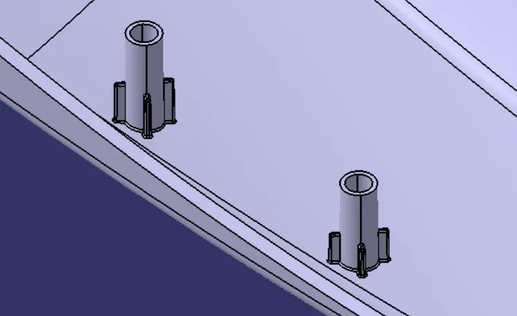
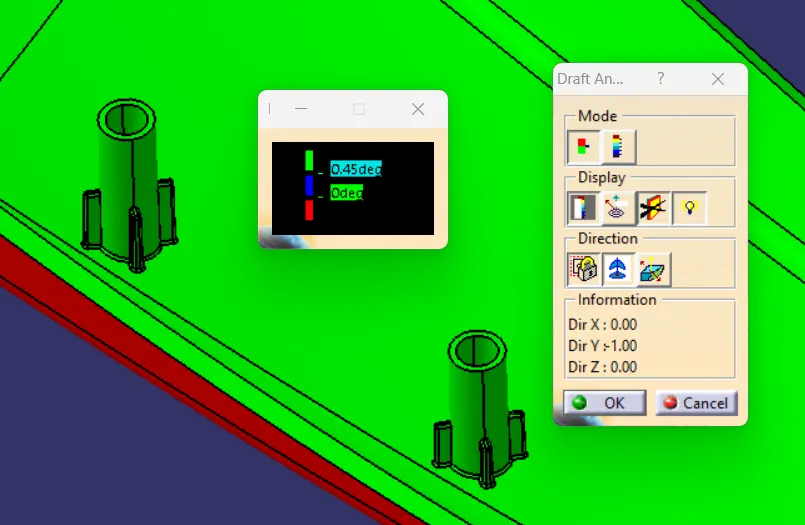
- The size of inner and outer diameter of the heat stake or thermoplastic pin is kept as per the manufacturer's preferance as long as it's wall thickness doesn't lie within 0.4 times of base wall thickness (wall thickness of main component).
- Both the inner and outer walls of the heat stake are drafted with the draft angle value of 0.5 deg.
- The remaining design is been kept according to the mastersection.
2) Locator Pins :
a) Application Of Locator Pin:
- The locator pin are of two types which are two way and four way locator whose function is to arrest the degrees of freedom of the component which is tobe fitted on the parent component.
- The locator pins also act as a guiding element while aligning two mating components, helps to locate the required position while assembly and act as a limiting element.
b) CAD design and design considerations of the locator pin along with draft analysis :
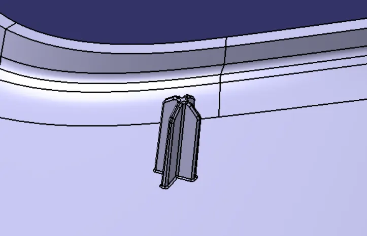

- The wall thickness of the locator pin should be 0.4 times of the thickness of parent component and height of the locator pin should be 5 times of the thickness of parent component.
- The draft angle value is 0.5 deg per side. Because of the draft, the tip thickness of the locator get reduces.
- The tip thickness must have minimum value of 0.75mm.
3) Support Ribs :
a) Functions of Ribs:
- Ribs improves stiffness and strength of the molded part without increasing overall wall thickness.
- They also facilitate locating and arresting the parts in assembly, provides alignment in mating parts of assembly and acts as a stops or guides for mechanism.
b) CAD design and design considerations of the support ribs along with draft analysis :
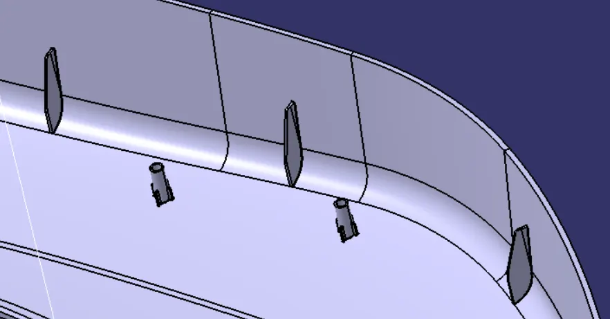
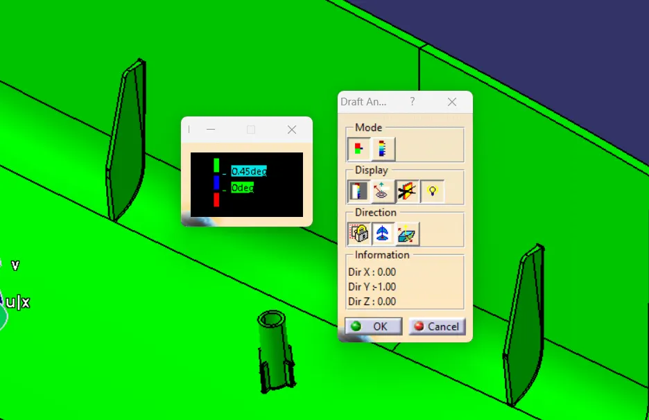
- rib height = 5 times component thickness
- draft per side is 0.5deg
- rib base thickness is 0.4 or 0.5 times component wall thickenss
- rib top thickness should minimum 0.75mm
- rib root thickness- 30% of wall thickness
- rib fillet - 0.25mm or upto 0.5mm if the thickness is more
4) Dog House :
a) Functions of dog house :
- The primary function of the doghouse is to avoid sink marks on the class A surface occures due to other B side features that could be later provide on the doghouse.
- Doghouse could be design with very less cross section area at the base which helps in elimination of the sink marks on class A surface.
- The secondary function of the doghouse is the length compensation in order to have proper reach of the B side features at required positions.
b) CAD design and design considerations of the Doghouse along with draft analysis :
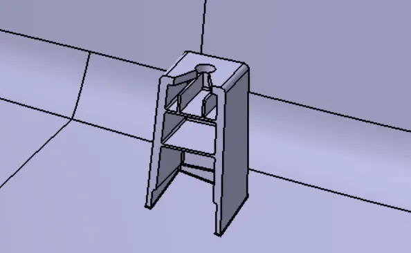
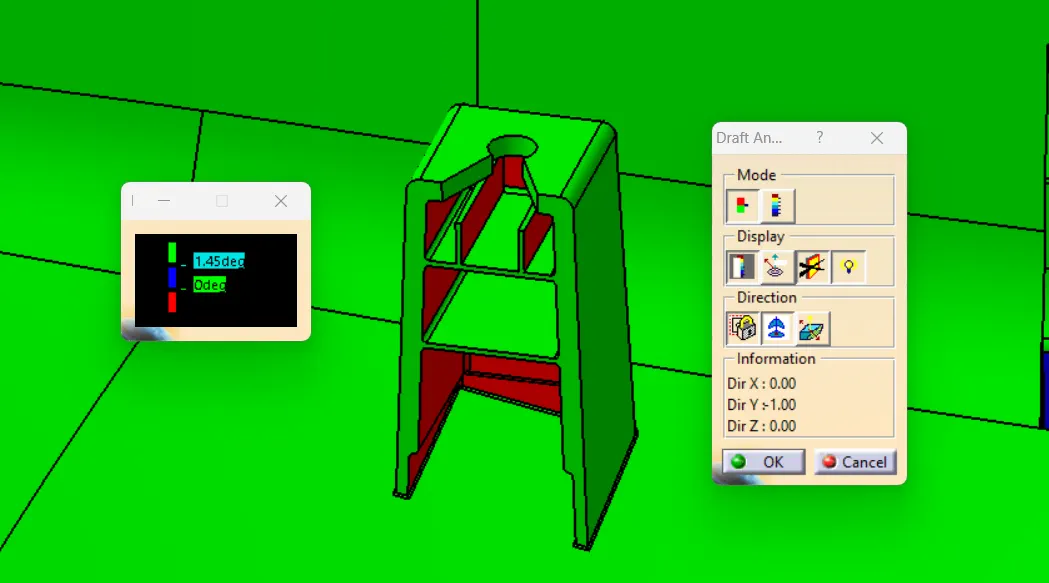
- The outer wall thickness of the doghouse is kept as 2.5mm and draft given to this wall is 1.5 deg.
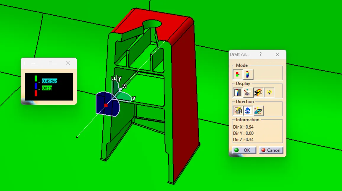
- The inner wall surfaces has 0.5 deg draft for the lifter opening.
- The outer wall of the doghouse has a inside cut at the bottom to reduce the wall thickness at the base. This ratio is shown in below image.
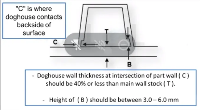
- draft analysis of main doghouse body along with main tooling direction with 1.5deg draft.
- draft analysis for side core with draft angle 0.5deg
5) Attachment Flanges :
a) Function :
- These flanges are created on the C surface and having a hole, so that the heat stake will pass through it and they both can have a permanant bond by forming a plastic weld.
b) CAD design and design considerations of the attachment flange along with draft analysis :
- There are two types of flanges on the basis of application, one is the heat stake falnge and another one is the locator flange.
- For heat stake flange the hole diameter is kept in sauch a way, the clearance between the hole and heat stake is 0.5mm.
- There should be enough surface are of the flange, so that the heat stake could form fastener head on top of the flange after thermal staking in order to have strong bond.
- For locator flange the hole diameter is kept in such a way, the clearance between the hole and locator is 0.1mm.
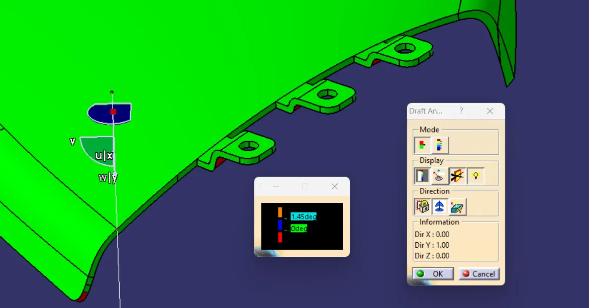
- The thickness of flange is same as that of the main plastic trim which is 2.5mm and outer sides of the flanges are drafted with 1.5deg draft.
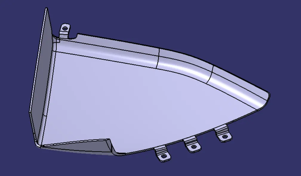
- Below pictures shows flange design and it's draft analysis example for the map pocket only. In exact similar way the flanges are designed for all ramaining components.
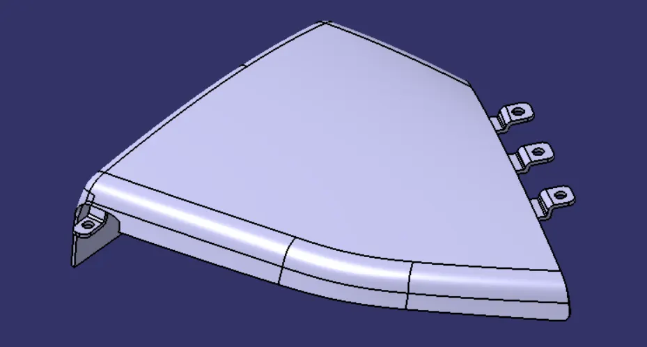
- draft analysis along the main tooling direction with 1.5deg draft.
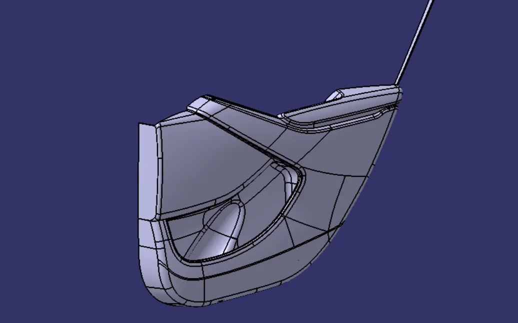
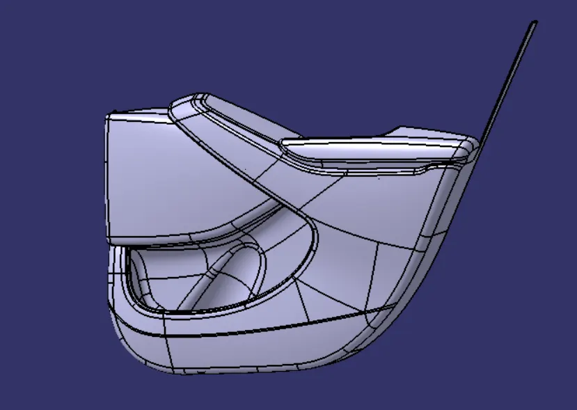
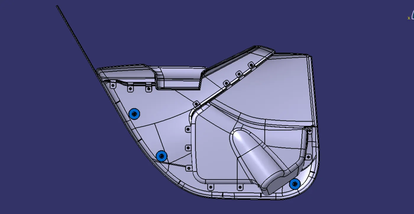
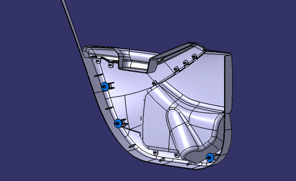
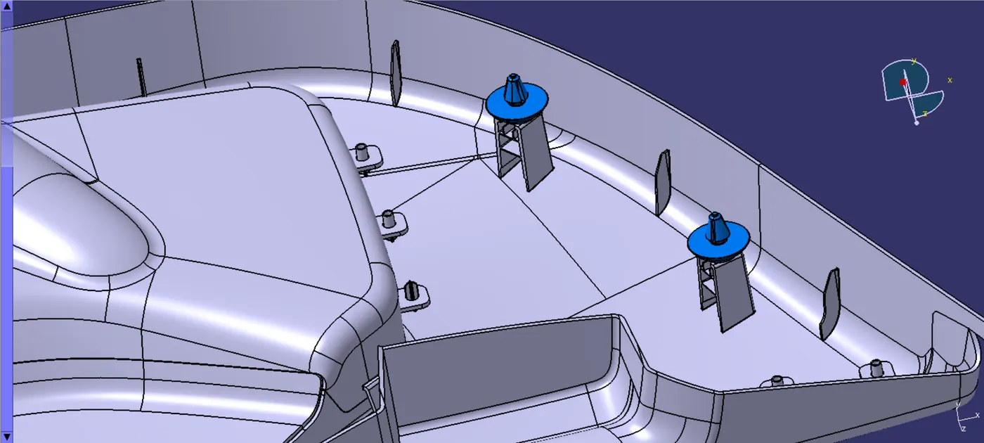
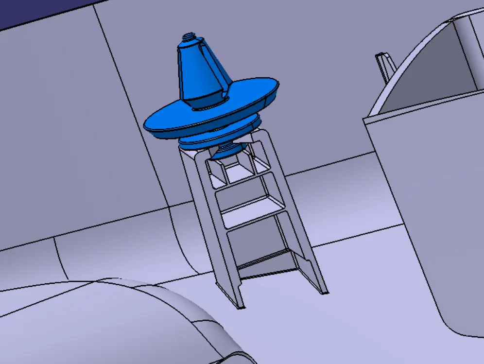
The complete assembly of the door trim :
Conclusion :
In this way, the complete door trim panel has been designed using the initial input data i.e. class-A surfaces and mastersections by following the plastic design rules and guidelines.