Hood design-Week 2
A report on hood design
Hood:
- hood is an essential part of an automobile vehicle which covers and protects the engine as well as other important components which assembled with the engine inside the engine bay.
- It also act as a door with locking mechanism which opens and closes in order to access the engine bay for serviceability.
- It is one of the impotant structural member which plays vital role in strengthen the overall vehicle's structure.
- It also provides safety for the passengers inside the vehicle as well as pedestrians during the collision.
Design steps of the hood using SIEMENS NX tool :
1) Design of hood inner panel as per the master section
- In the initial stage the styling department provides the outer skin data. After analysing the skin part, the hood outer panel and inner panel needs to be design accordingly.
- The design approach being use in here is bottom to top method in which an assembly file is been created and all the necessary parts been added into it. (hood outer panel, hinge assembly, striker)
- After creating an assembly file in nx and saving it in a folder, all the necessary components is been added into the assembly with proper naming and saving all those in the same folder.
- By doing so, all the components will be there in the assembly navigator.
- In this assembly environment, it is important to have a datum csys for referance around which all the necessary work will be done.
- therefore a datum csys is been created at (0,0,0) in assembly space.
- Now the assembly constrains needs tobe apply w.r.t. datum csys.
- here the hood outer panel is the main platform for the entire assembly, so the fix constrain is been given to it.
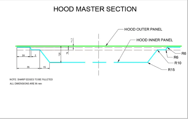
- The further design will be proceed according to the provided master section.
- Get into assembly navigator. inside the assemblies tab, select 'create new' option, a window will pop up. name it as inner panel and say ok. the inner panel will be there in assembly navigator as an empty part file in which the inner panel will be design.
- Now activate the inner panel by double clicking on it. now the hood outer panel will be the reference surface on which the inner panel gets designed. so we have to get linked surface from the outer panel to create inner panel.
- for that the command 'wave geometry linker' is been used and the exact same surface is created by selecting outer panel at 1.7mm downward offset from it as per the master section.
- This is going to be the exact surface on which all the necessary work will be done to form the inner panel.
- Before starting work on inner panel again it's important to make sure that, in assembly navigator the inner panel is activated and provided with datum csys.
- As per the master section we can see from the front, the panel looks symmetric on either sides from the centreline. So we can do all the work just on half of the section and then we can mirror it on the other side. so it will eliminate lot of efforts and time to design it.
- For that the command 'intersection curve' is been used which is present in the 'curve' tab. it will create the intersection line right at the middle of hood inner panel.
- To cut the panel in half, the command 'trim sheet' is been used which is present in 'surface' tab
- Now we have half section of the panel on which all the necessary work will be done.
- As we look the master section, the panel got deep drawn in two steps. first is at 4mm downward and second is at 25mm downward from the outer panel.
- Since we have to offset the same surface multiple times, the environment might get little busy for visualise the panels. so we can hide and show the panels from part navigator as per the requirement for better access to select individual panel to work with.
- After offseting the panels accordingly we got the entire half panels below the outer panel. But we just want a perticular profile form these panels with given dimensions.
- In case of the first offseted panel (1.7mm from outer panel) we just want the outer most strip at 20mm distance. So we create the outer curvature profile using 'offset curve in face' (present in 'curve' tab) at 20mm distance(inward). And we trim the inner section of the panel using that offseted curve as a trim tool by 'trim sheet' (surface tab).
- Now in case of the surface which has been offseted at 4mm from outer panel, we want a strip from it whose edges are situated at 22mm and 35mm from the outer edge.
- For that again the offset curve in face is been created on the surface at both of the distances and the surfaces across the curves is been trimed using trim sheet.
- This is how we get the 2nd surface strip.
- Now for the last offseted surface which is at 25mm from the outer panel, we want complete surface with reduced dimension which is 50mm less from the outer panel edge.
- For that again the offset curve in face is been created at 50mm inward and used it as a trim tool for trim sheet.
- Now we get all surfaces at required distances and with required profiles, we are ready to join them by using 'through curves' command in surface tab.
- In order to joine the adjacent surfaces, select 'through curves' command, a window will pop up which will be asking for selecting curve or point. then select the inside edges of both of the surfaces one after another and the prewiew will be displayed showing the surfaces is been joined within the edges. say ok.
- The similar process is been repeated to join the last surface with the middle surface.
- Now its time to apply edge blends to all the sharp edges.
- But before that all the surfaces needs to get sew together. for that select 'sew' option in surface tab, a window will pop up and will be asking for selecting the surfaces tobe sewed.
- Select all the surfaces and say ok. all the surfaces is been joined together and will became as a single surface.
- Now provide edge blends to the sharp edges using 'edge blend' command with required radius.
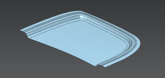
2) Emboss definations and embose creation
- Its very important to reduce the weight from the hood inner panel in order to improve the performance and fuel efficiency of the vehicle.
- This could be done by cutting some portion off from the inner panel
- Emboss defination plays vital role during the crash and the pedestrian's safety.
- When any vehicle subjected to frontal crash, the first impact from the opposite side always faced by the hood and the entire impact force transmitted through it towards the passenger's cabin.
- So it becomes really important how the emboss section cutting has been done on the inner panel in order to transmit crash impact outside from the passenger's cabin to minimise the injuries to passengers inside the vehicle.
- Steps to create the emboss on inner panel:
- First we need create a sketch of the emboss profile by selecting the appropriate plane. after creating the sketch we need to project it on the inner panel surface using 'project curve' command in curve tab.
- The first emboss on the inner panel will be like, considering the empty space for the striker and hinge mounting. The direction of this emboss will be 15mm towards the outer panel.
- The picture regarding above process is shown below.
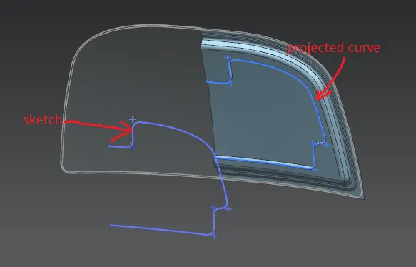
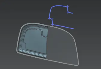
- In order to emboss this profile on the inner panel, select 'emboss' option in surface tab, a window will pop up which will be asking for selection of the curve, face to emboss, emboss direction(towards outer panel),end cap geometry(embossed faces), location(offset), offset distance(15mm), draft angle(10). after filling this data say ok. the embose will be form on the inner panel.
- After this all the surfaces needs to get sew together and edge blends should applied to all sharp edges with required radius.
- Now in order to remove the material from the inner panel, the emboss is been provided in specific defination. For that the required sketch is drawn and is been projected on the surface of inner panel. Using that projected sketch/curve the following emboss is been created on inner panel 5mm towards the outer panel.
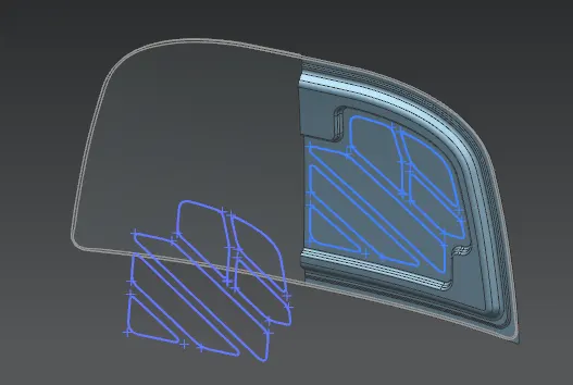
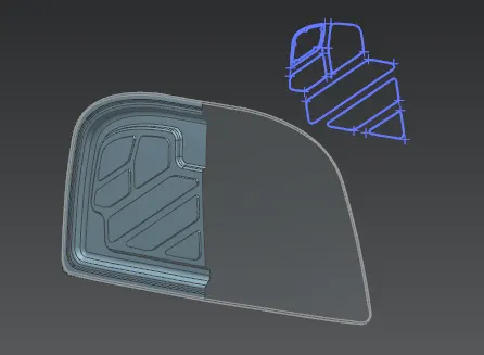
- As per the master section the distance between outer panel and the bottom most surface of the inner panel was 25mm. This surface is been embossed twice with 15mm and 5mm.
- therefore the clearence between outer panel and the last emboss surface is 5mm. This 5mm clearence is necessary for the mastic appplication to join outer and inner panel together.
- Mastic data:
- The cutting profile on the last emboss sections will be come up with mastic data points. These are the points on which the mastic glue will be applied.
- Each mastic data point provides strength within 80mm of diametric range. Therefore the mastic placement has been done accordigly.
- The mastic joining process plays vital role in NVH control because it reduces the NVH levels and enhance scilent and stable performance.
- The material is been removed from the inner panel using trim sheet and the offseted emboss profile with mastic points on the surface as a cutting object.
- All the surfaces got sewed together and edge blends are provided to sharp edges with required radius.
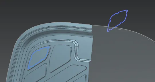
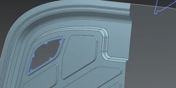
- The same process has been applied to the remaining sections.
- Hinge Emboss:
- Now the hinge which is to be mount on the hinge emboss has a flat surface so we cant emboss the existing surface because it is curved.
- For that we need a reference(end cap geometry) to create flat emboss surface. So the datum plane is been introduced near about parallel to the hood at a distance closer to it for better visuals.
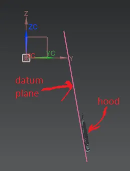
- Now rest of the process of creating the sketch profile (on global plane) and projecting it on the inner panel's surface is similar.
- Using this projected curve the hinge emboss is been created. The end cap geometry for this emboss is the datum plane introduced recently for the flat surface emboss.
- After this the surfaces got sewed together and edge blends are applied to all sharp edges.
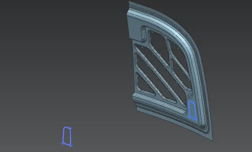
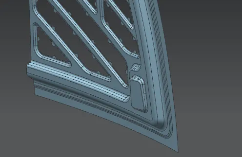
- Mirror Geometry
- Now its time to mirror the half section of the inner panel on the other side. But there might be chances of being some gaps in between because the panel is curved & we wont be able to sew the surfaces properly.
- For that we need to extend the surface little bit ahead from the middle and then we will trim it using trim sheet with intersection curve as a trim tool.
- After this there will be no gaps left between the two halfs. Now we can perform the sew operation successfully.
- The two bottom round corners is been cutted by using offset curve in face at 0.1mm distance as a trim tool with trim sheet command.
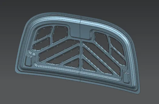
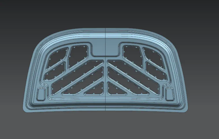
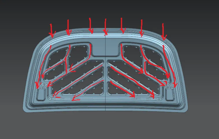
- The picture shown in below explains the embose definations and how the crash impact transmitted through it.
- In the first picture the embose definations are showed which are cutted on inner panel and the second image shows how the crash impact force gets diverted towards the hinge emboss instead of going inside the passenger's cabin.
- Assembly of hinge on either sides
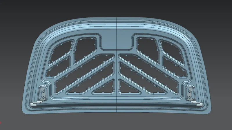
- Click on assembly navigator and activate the hood assembly and switch to the assemblies tab. Inside it click on 'move component'. A window will pop up then click on the hinge. choose the motion as 'dynamic'. After that click on 'specify orientation', the arrows will be shown on the hinge.
- The reqiured orientation is been given to the hinge by draging the arrows and giving the rotation.
- After this the constrains is been applied such that, the 'touch align' is applied between the hinge emboss surface and hinge hood part's back surface. As well as the 'parallel' constrain is applied between hinge axis and x-component of the datum CSYS.
- In this way the left side hinge is assembled with the inner panel.
- Now we can mirror the left side hinge assembly on the right side by using 'mirror assembly' option. In mirror assembly wizard there is one important thing which is, having assosiative mirror between both of the parts to get the same assembly constrains on the other side
- In this way both the hinges are assembled to the inner panel.
- Latch Trajectory
- When the hood will get mounted on the vehicle, it's opening and closing should be work properly. Also the locking mechanism of the striker and latch should work perfectly.
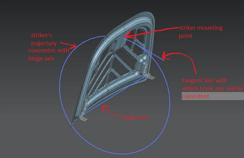
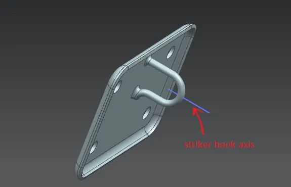
- Since the hood opening and closing is in angular direction so in order to have proper locking between the latch and striker, the striker must have appropriate trajectory.
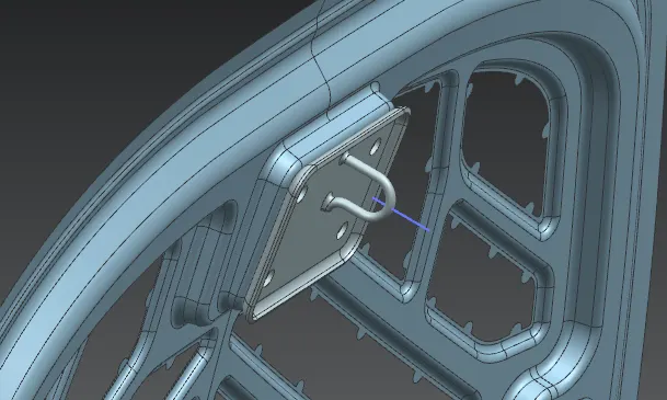
- For that the sketch is been created on inner panel and striker regarding latch trajectory for giving assembly constrains between striker and inner panel.
- the following picture shows and explains the latch and striker trajectory.
- Striker Assembly
- For the striker assembly again we have to provide striker emboss because the inner panel surface is curved. For that activating the hood assembly and bringing the striker at required position, after that the trajectory constrains has been given to it.
- Using the wave geometry linker the back surface of the striker is been extracted at that position in the inner panel.
- Then we have to extend this surface from all sides 5mm outward for giving further edge blends and to have good fit of striker on it.
- Then this surface is been joined to the inner panel using 'Law Extension'. The surface angle is been kept as 80 degrees for the positive draft and it is extended around 30mm approx which will intersect inner panel.
- The excessive surfaces is then trimmed using trim sheet. after that sewing and edge blending has been done.
- Holes creation on the hinge emboss
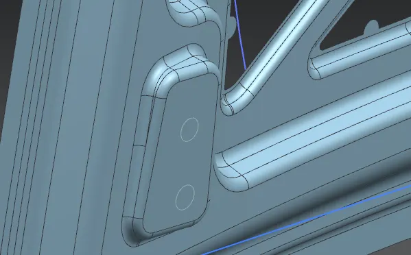
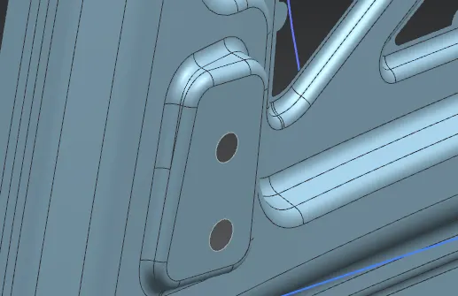
- In order to create holes on the hinge emboss at a position where hinge holes are present, we have to extract that geometry on the inner panel using wave geometry linker.
- After extracting the hole's profile(linked composite curve) on the inner panel at required location, the surface is been trimmed using that curve as a trim tool with the trim sheet.
- Hinge Reinforcement
- Because of the holes cutted on the hinge emboss, the surface/sheet might loose some strength around the holes. In order to compansate that the reinforcement is been provided over there.
- For that the back face of the hinge emboss is been used as a linked surface using the wave geometry linker and then thickness is provided to it as 1.5mm.
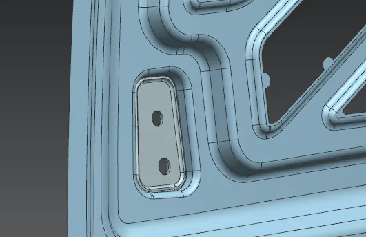
- Before proceeding for the hemming, the outer surface profile of the inner panel needs to get reduced by 2.5mm because the inner panel needs to get hem under the outer panel without any interferance.
- This has been done using trim sheet with offset curve in face.
- Hemming:
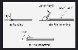
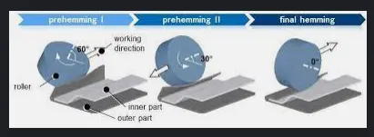
- In hemming process the inner panel gets wrapped under the outer panel by bending some portion of outer edge of the outer panel around the inner panel's outer edge.
- This process is done by the application of rollers pressing the outer edge of the outer panel towards the inner panel in no. of bending stages.
- Each bending stage presses the outer panel's edge close to the inner panel. In the last application of the roller press the edge of the outer panel completely gets wrap around the inner panel.
- Procedure of modeling the hemming in NX CAD:
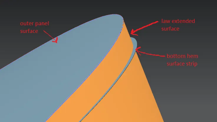
- Inside the assembly navigator make sure that the outer panel is activated. We have to create a flat surface around the outer edge of the outer panel at an angle inclined towards the inner panel using law extension.
- First we have to create bottom hem surface strip at the boundry having the width of 6mm as per the master section. For that a suface is been offseted form the outer panel at 2.65mm downward. Using offset curve in face at 6mm and trim sheet the required surface strip is been formed.
- After that selecting law extension command, a window will pop up which will be asking for select curve (select the outer edge of outer panel), select face(select the face of panel, make sure that the direction should be towards the inner panel), lenth law(constant, value- 30mm approx), angle law(80deg towards inner panel), side(select 'one sided') say ok.
- The surface will be created from outer panel's edge of 30mm width and 80 deg inclined which will intersect the bottom hem surface.
- Then the excessive surfaces will be trimmed using trim sheet and there will be closed surface profile around the inner panel.
- After that the 'surface blend' command is been used to round the surface using three face blend. The law extension surface could get hidden to see the heming surface.
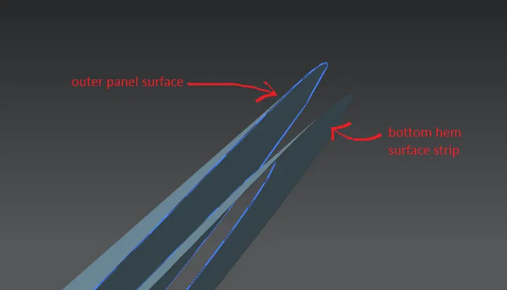
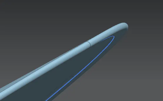
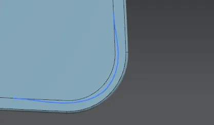
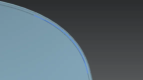
- Now it is important to provide some corner relief by cutting some portion off from the bottom hem strip.
- For that a sketch profile is been drawn using 'curve on face' and using it as a trim tool with trim sheet.
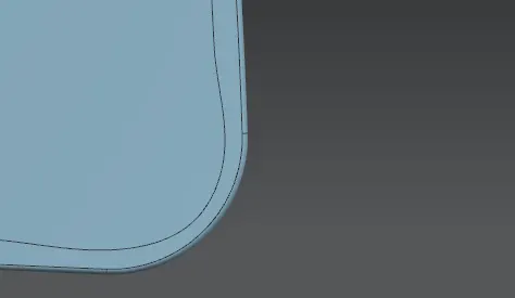
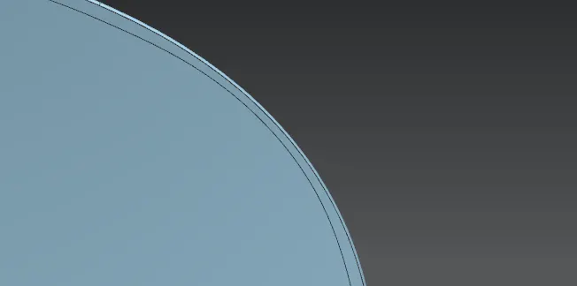
- After this it's time to thicken both of the panels. For that, click on surface tab there will be a command names 'Thicken'.
- After selecting it a window will pop up which will be asking for select face(select face of outer panel), offset1(enter value as 0.75mm) and change it's direction towards the inner panel. say ok
- For thickening the inner panel, activate it in hood assembly and following the process as mentioned above. Only direction of thickening will be towards the outer panel.
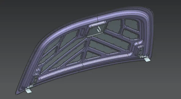
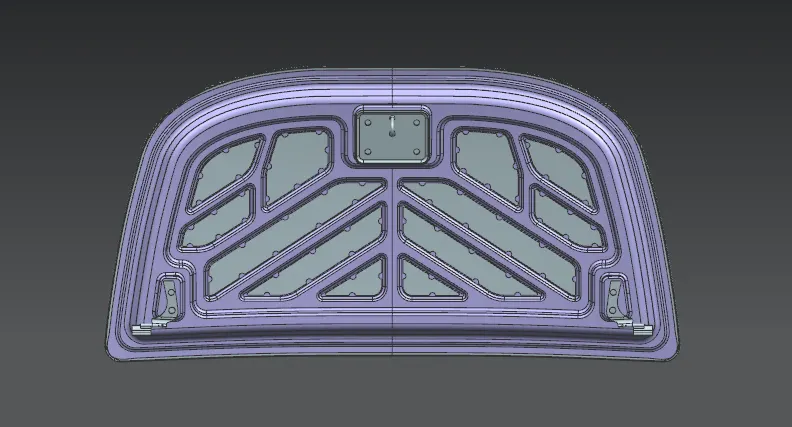
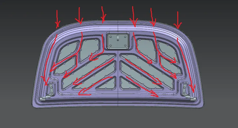
- In this way the modeling of hood inner panel and outer panel and their assembly has been done.
- Deep Drawing Process:
- The deep drawing process is a forming process which occurs under a combination of tensile and compressive conditions. A flat sheet metal blank is formed into a hollow body open on one side or a hollow body is formed into a hollow body with a smaller cross-section.
-
Deep drawing processes are divided into three types:
- Deep drawing with tools
- Deep drawing with active means
- Deep drawing with active energy
- In the automotive industry, deep drawing is usually carried out using rigid tools.
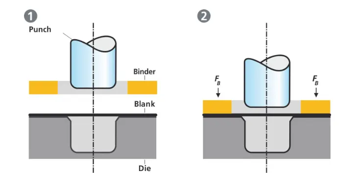
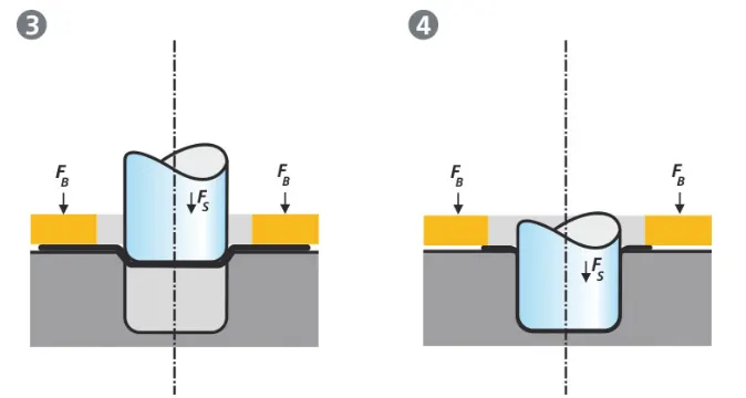
- The figure illustrates the deep drawing process. The rigid tools consist of a punch, die and binder. In deep drawing, the plate holder closes after the metal sheet blank has been inserted.
- Next the sheet is clamped between the die and the binder. This process slows down the flow of the sheet while it is being drawn and thereby prevents wrinkles from forming under the binder. The punch stretches the sheet over the die radius and forms it in the die. The amount of punch force necessary for forming is thereby continually increased up to the lower dead center of the punch.
- Whereas in pure deep drawing there is no reduction of sheet metal thickness, forming is achieved in stretch forming purely as a result of a decrease in sheet metal thickness. Stretch forming is extensively used for the forming of only slightly curved parts with low depth of draw (e.g. roofs, doors).
- When drawing complex car body parts in practice, there is usually a combination of stretch and deep drawing involved. It is necessary that the sheet metal is stretched as well as possible without reaching the material’s limits (e.g. splits, wrinkles).