Project 2
A REPORT ON PROJCT 2
1) defining all the cat parts
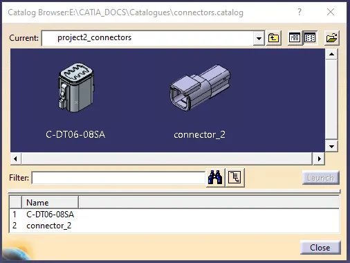
a) defining the connectors & catalogue creation:
- open any of the connector from project 1 data in part design w/b > identify the bundle connection and connector connection sides > give the geometrical parameters (points and axis) on the bundle connection(point only) & connector connector connection side > also identify the cavity slot on the connector if any and give the point & axis on the contact surface accordingly.
- switch the w/b to electrical part design > click on 'define connector' option > click on the connector > enter the no of terminals in defination window > click on ok.
- select 'define connector connection point' > click on the connector > defination window will be there > select point for representation > select face for contact > select y axis for co incidence > select x axis for orientation > click on ok.
- select 'define bundle connection point' > click on the connector > defination window will appear > select face for representetion > select the point > select the same face for initial condition > say ok.
- select 'define cavity connection point' > click on the connector > select pint for representation > select face for contact > select y axis for coincidence > select x axis orientation > ok.
- in this way the connector has been defined electrically and same method could be apply for rest of the connctors.
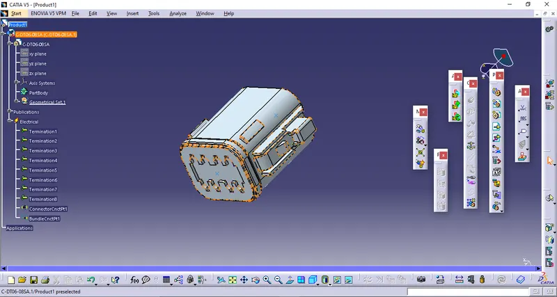
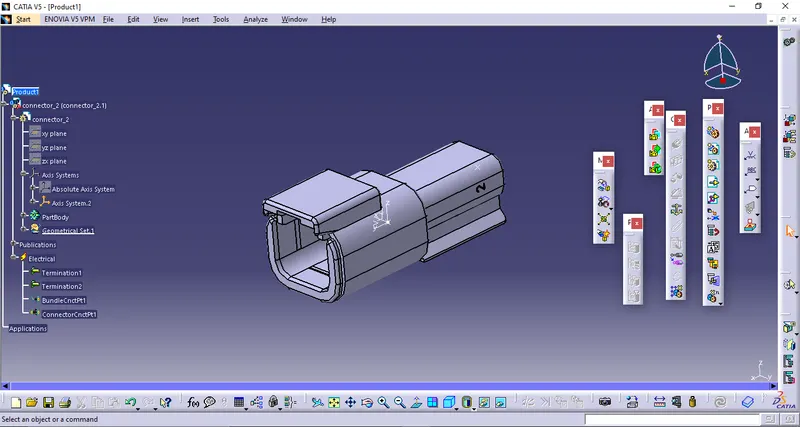
- to create a catalogue for storing the connectors go to file>new>catalogue document>ok.
- a window will appear. select the add family option>a window will opo up>give the family name>select the type 'electrcal'>ok.>file>save>give the catalogue name>save
- open one of the connector in electrical part design workbench>click on 'store device option'>a window will pop up>brouse the catalogue and select it>select the family>ok.the connector has been stored in the catalogue.
- the same procedure can be used to store the remaining connectors.
B) defining clamps and clips
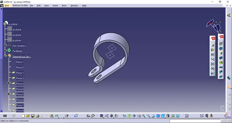
- after downloading .igs p clamp file open it into catia's part design workbench.
- in order to give the geometrical parameters click on point option available on reference element toolbar>a window will pop up>select point type as 'circle, sphere, elips'>click on any circular edge of the p clamp>a point will appear on the middle of a p clamp on the perticular side which has been selected.
- select the plane option>a window will pop up asking for the plane type and reference>select 'parallel through point' option for plane type>select the circular surface of the p clamp for reference>select the point that has been created earlier. a plane will appear which is parallel to the side of the clamp and coincident with the point.
- to create a point and plane on the other side of the clamp the same two process can be used mention above.
- these geometric parameters was added for the entry and exit sides for routing the wire.
- now its time to create another plane for the base on which the wire will lay on.
- for that select the plane option>a window will appear>select 'offset from plane' for plane type>select the internal flat surface of the clamp for reference>give the offset value accordingly>the base plane will be generate.
- upto this the p clamp is a cad model. it has to be define as an electrical component. for that switch the workbench to electrical part design.
- select 'define support part' option>click on the p clamp>a window will pop up>adjust the orientation of clamp to set entry side for the wire>click on the point of selected side for entry>select the plane for the same>select the plane on the opposite side>select the base plane>ok.
- to define the exit side of the clamp for wire adjust the orientation to select exit side>select 'define support part' option>click on the p clamp>a window will appear>select the point>select plane>the opposite plane has already been selected>select remaining plane for the base.
- in this way the p clamp has been defined geometrically and electrically.
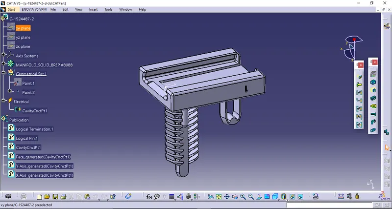
- cavity clip is a mountig equipment which is to be attach to the connector.
- to define the cavity clip, open it into the catia's part design workbench>give the geometrical parameters (point & axis) on the region of mating section>swith the workbench to the electrical part design>select the define equipment option>click anywhere on the mounting clip model>select define cavity connection point>click on the cavity clip>pop up window will appear>select origin point for representation>select mating surface for contact>select y axis for coincidence>select x axis for the orientation>ok.
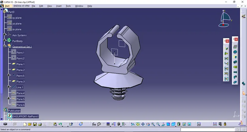
- to define fir tree clip, open it in part design w/b and give the points and planes for entry and exit side and the plane for the base.
- now switch w/b to the electrical part design and define fir tree clip as support. after that in defination window give the parameters for the entry side and say ok. again define it as support and give the parameters for exit side in defination window. after this save it.
2) assembly of components
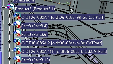
- open a new product in assembly design > right click on the parent of a tree > click on components > select existing component > brouse 'back door assembly' file and insert it in w/b. the back door assembly will be a seperate product under the parent.
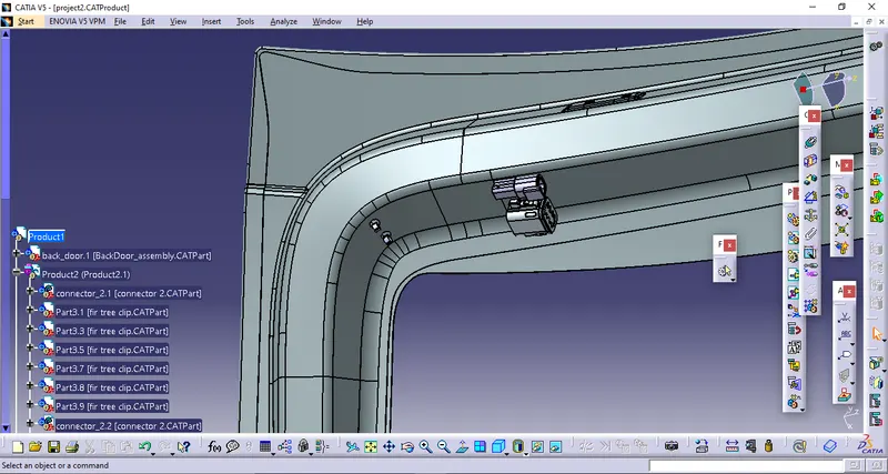
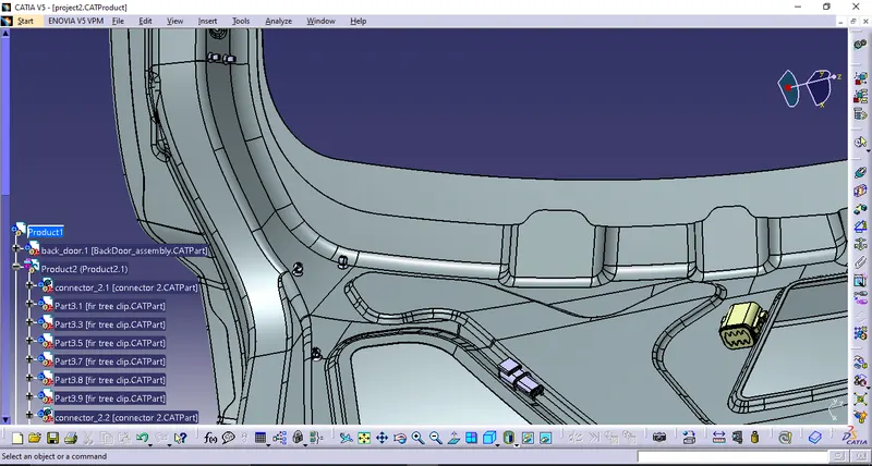
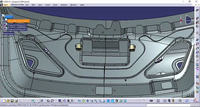
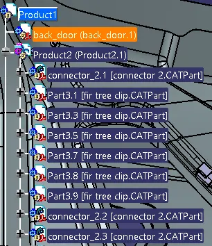
- again right click on the parent of tree and get a new product under it. now by keep selecting this product, import all necessary connectors & clips etc. from catalogue one by one after placing each of them one by one sequencially on their desire positions by using manipulate,compass & snap tools.
3) harness assembly
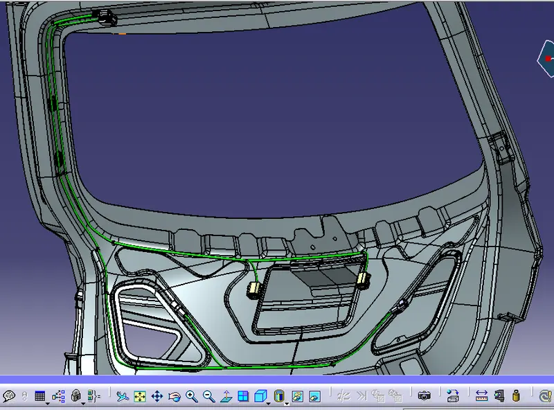
- now switch the w/b to electrical harness assembly > select geometrical bundle option > select the product from tree in which all electrcal equipments are present > the product will turn into electrical.
- now switch the w/b to electrical harness installation > route the wires using branch defination option by connecting the electrical components in desire path.
- give appropriate defination to the multibranchable like diameter, bend radius, slack, clearence etc.
4) adding protective coverings
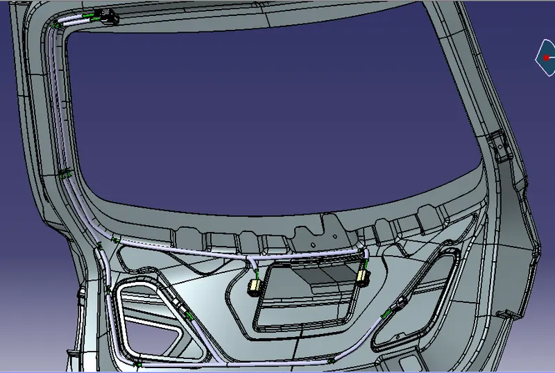
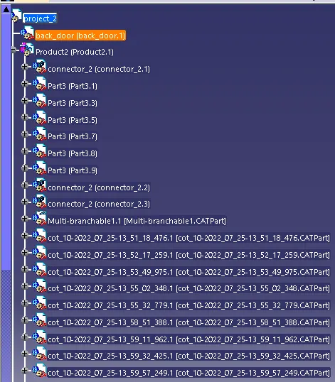
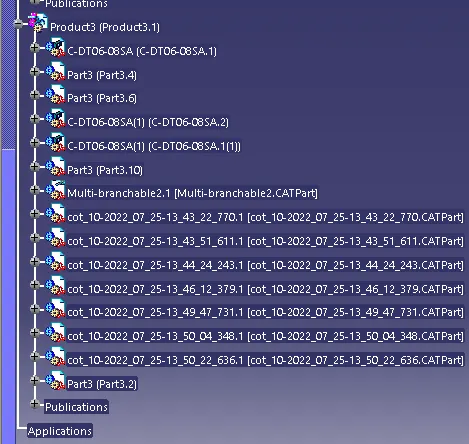
- to add cot tubes on the wire, click on protective covering option > a window will appear > click on catalogue > brouse respective catalogue > select the tube diameter wise > ok > click on the wire > give start and end extrimity accordingly.
5) harness flattening
- get the existing harness assembly in the 'electrical harness flattening' workbench
- open the new product and switch the w/b to electrical harness flattening. > select flattening parameters option > a window will pop up > give the parameters as shown in the below image.
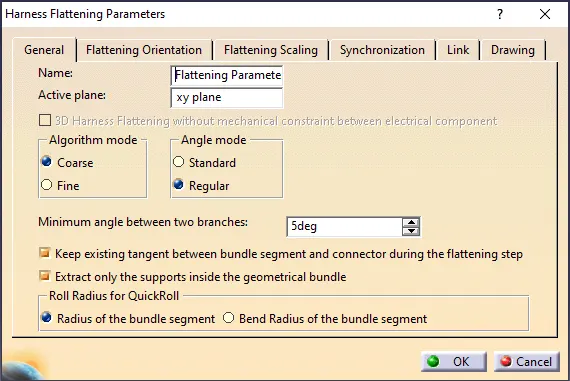
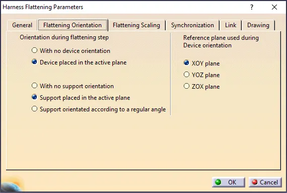
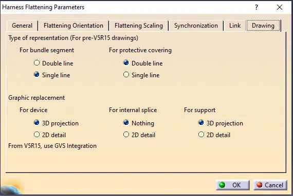
- click ok. all options will be activated > select extract > go to harness assembly window > click on parent of multibranchable of the tree. the harness will be extracted in flattening w/b.
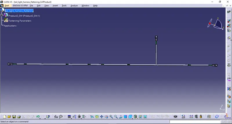
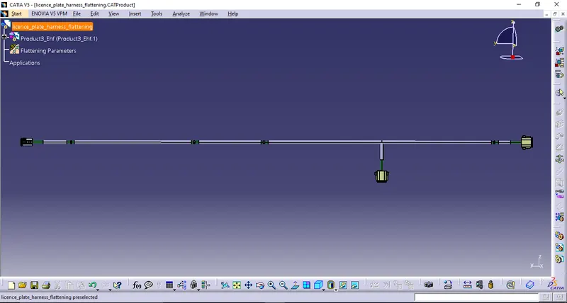
- select 'flatten' option > select any plane or face with which the flattening is to be done > select the main branch > select all branches option > ok. the entire harness will get flattened.
- now adjust the orientation and positions of the components as per requirement in assembly design.
- also the positions of the wire could be adjusted by using options like rotate,quick roll,straighten etc.
6) drafting of harness flattening
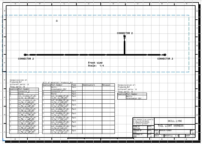
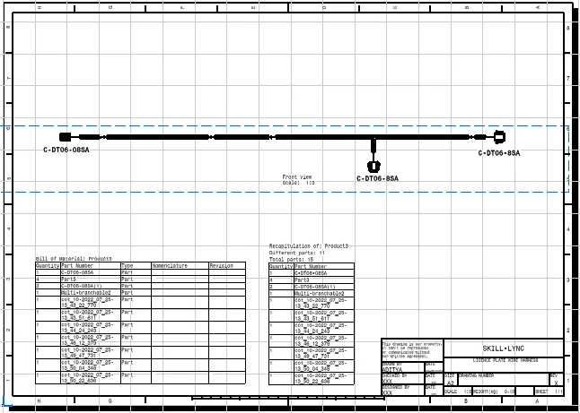
- go to file > new > drawing > ok > select sheet size, iso , landscape > ok.
- drafting w/b will open > click on front view option > go to flattening w/b > select the plane or face which was selected for flattening > ok.
- the 2d representation will appear on the sheet > click outside the sheet.
- right click on orange coloured dotted border > properties > enable 3d wireframe > always visible > ok.
- position the drawing on the sheet by draging dotted orange border.
- the drawing scale and sheet size could be change from sheet properties by right click on sheet on tree.
- the parts annotations could be given using annotations and text tools from insert option.
- go to edit > sheet background > frame and tile block > select any sample template > ok.
- go to edit > sheet background > working view > insert > generation > bill of material > bill of material > click on the sheet > bill charts will visible on the sheet > adjust the position of them accordingly.