Design of backdoor
A Report On Backdoor(Tailgate) Design Of The Passenger Car
Objective:
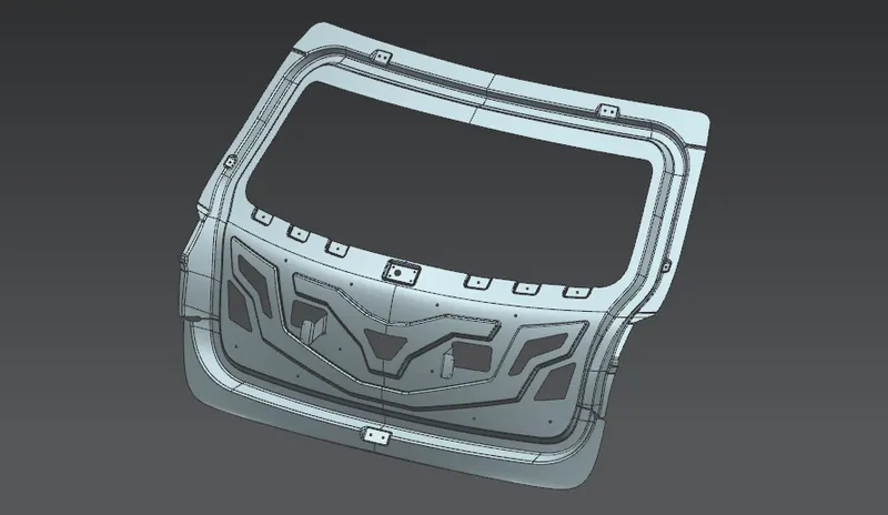
To design and model the Inner Panel of the backdoor with the Reinforcements and embosses for Hinges, Latch, Gas-Stay and Wiper Motor from the given styling surface using NX12. Perform draft analysis on the inner panel and create an assembly of outer panel, inner panel and reinforcements of hinges, latch, wiper motor, gas stay.
Backdoor:

- Backdoor is one of the major closure member in automobile which allows to access the boot, spare wheel and other utilities present in the field.
- Backdoor is the unit which is an assembly of outer panel, inner panel and all necessary reinforcements.
- Also back door come up with some other commodities like tail-lamp, wiper motor, latch, rear windshield glass,gas stay, registration plate, harness, plastic trims etc.
Backdoor Assembly And It's Components:
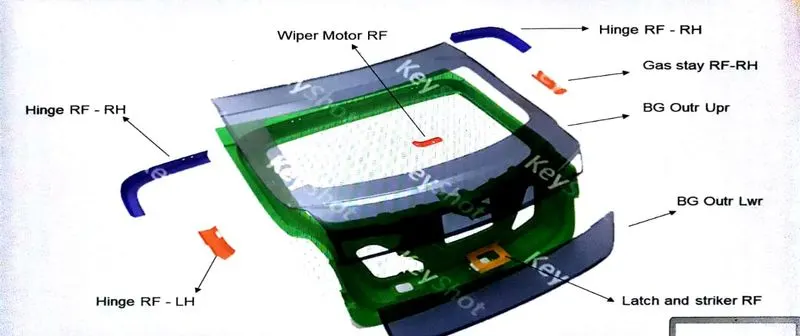
- Inner panel
- Outer panel upper
- Outer panel lower
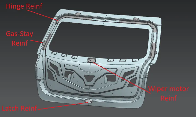
- Hinge reinforcement LH & RH
- Gas stay reinforcement LH & RH
- Wiper motor reinforcement
- Latch reinforcement
Given Class A surface:
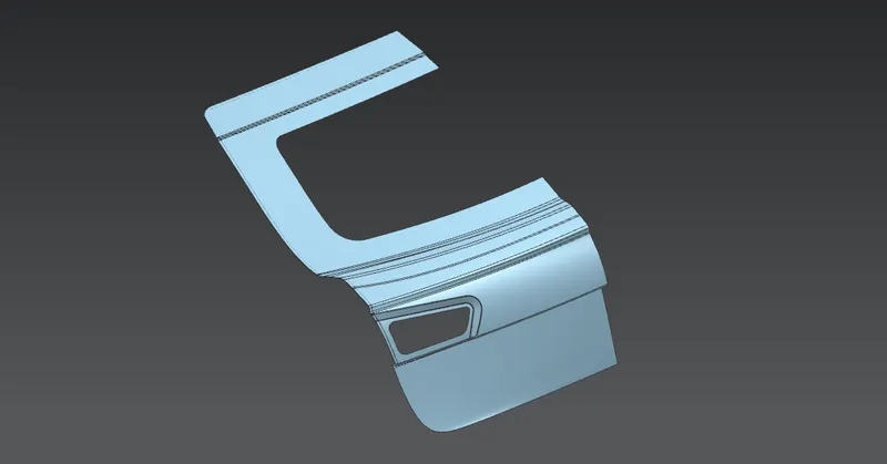
Inner Panel Design:
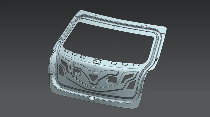
- Inner panel is the main supportive component of the whole tailgate assembly. It holds and supports all other components of the assembly by different joining processes.
- Inner panel carries different loads and transmits forces at different operating conditions so it needs to be design considering all these factors.
- Also it plays important role in the ergonomics like rear visibility criteria and the luggage area.
- It also provides safety during rear crash collision and made the crash impact transmit towards the hinges.
- It consists the sealing flange which sits on the weather strip in closed condition which provides sealing of the cabine from the outside environment.
- Tooling direction:
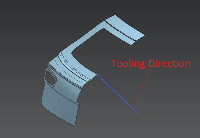
- The blue line showed in the picture is the tooling direction for the deep draw tool along which the tool will draw the inner panel.
2. Sealing flange
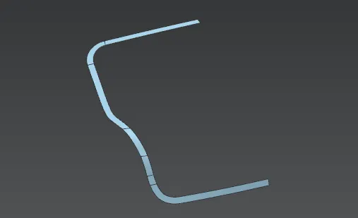
- The surfaces are offseted from outer upper and outer lower surfaces at 25mm inward to create the sealing flange.
- A profile shape of the flange is sketched on the offseted surfaces and they've got trimmed to get flange profile.
3. Mastic surface
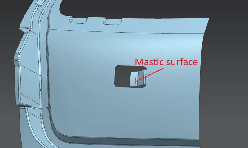
- the small portion of the inner panel's surface is been ripped and bend towards the outer panel to have a mastic joint between the inner and outer panel.
- This surface will be on both sides of the inner panel after mirror.
- The mastic joint form between the inner and outer panel will improve strength and NVH control.
4. Embosses
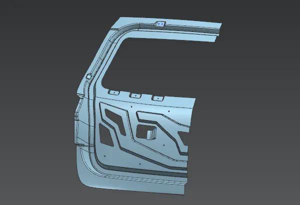
- The V and Y emboss is been given to the inner panel in order to direct the forces towards the hinges and gas stay.
- Also the embosses for hinges and gas stay is been given to the desire position before doing mirror.
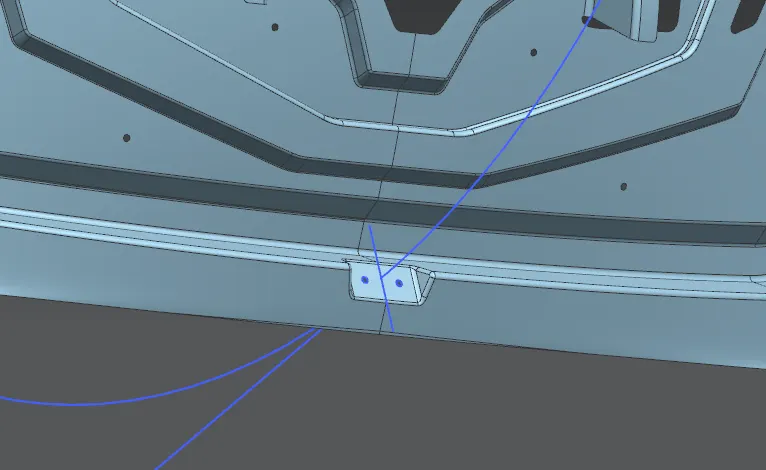
5. Latch trajectory and latch emboss
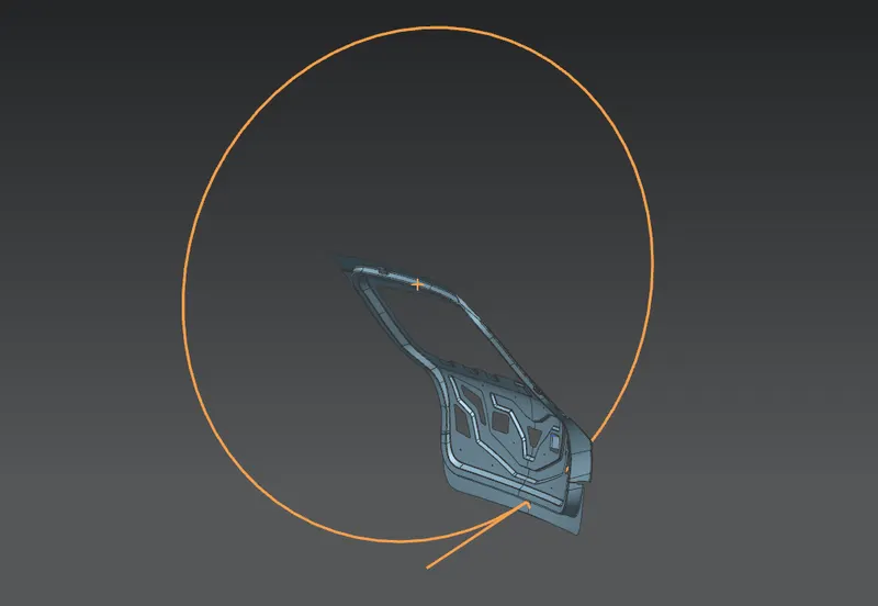
- After mirroring the panel, the hinge axis point is been given about which the latch travel trajectory is drawn(concentric to hinge axis) which is exactly tangent to the line which is normal to the position of the latch.
- After fixinging position of the latch the emboss is been given for latch at that position.
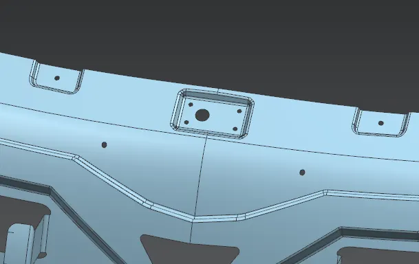
6. Wiper Motor Emboss
6. Draft Analisys of Inner Panel
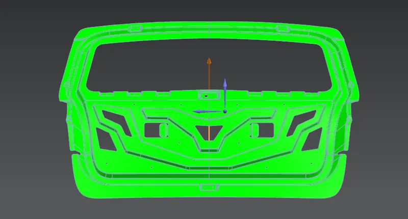
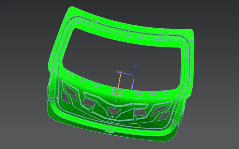
- Draft analisys is been done on the inner panel to check whether the draft is positive or not. Draft angle is kept between 10 to 20 deg.
- The draft must be positive for proper deep draw operation. If it is not, the surface of the panel won't be good as well as it will affect the porduct life cycle of the tool.
- Green region on the panel indicates the positive draft and from yellow onwards indicates the receding draft.
7. Thickening of the inner panel
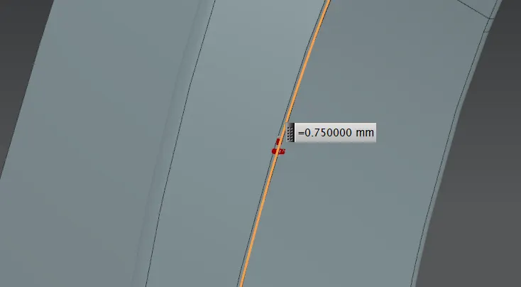
- Thickness is been applied to the inner panel of 0.75mm.
Reinforcements:
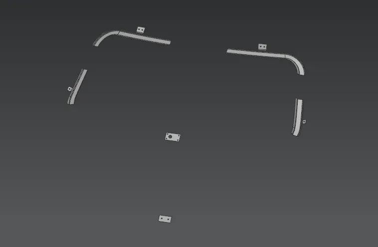
- The reinforcements is been given at the places of hinge mounting, gas stay mounting, latch mounting and wiper motor mounting to compensate the strength of the inner panel due to the addition of these commodities.
Hemming:
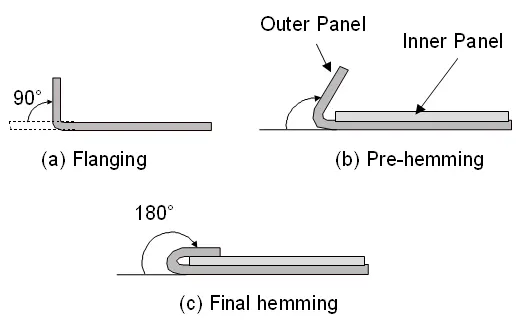
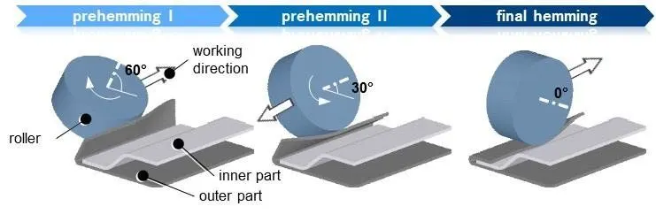
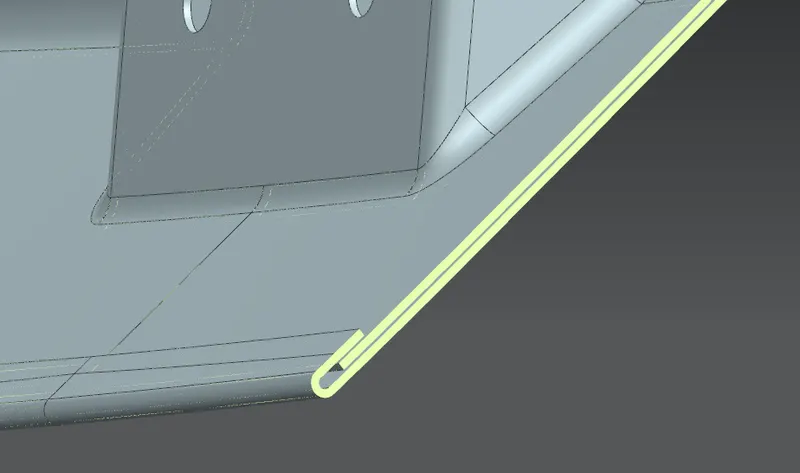
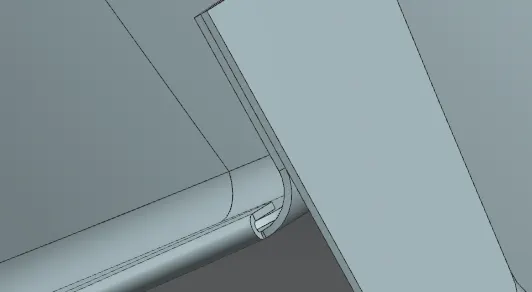
- The hemming flange is been offseted at 2.65mm from the outer panel and is reduced to 7mm wide. a surface is law extended from outer panel's edge at 90 deg which goes across the hemming flange. Then three face blend is given to these three surfaces to form smooth round surface.
- The corner releifs are given to the edges.
Conclusion:
- In this way the backdoor is been designed using given styling surface with the inner panel design having different embosses and essential reinforcements with draft analysis.