Wiring harness routing & packaging Rules Week 3 Challenge
A challenge complition report on P Clamp, backshell,corrugated tubes, catalogue of corrugated tubes.
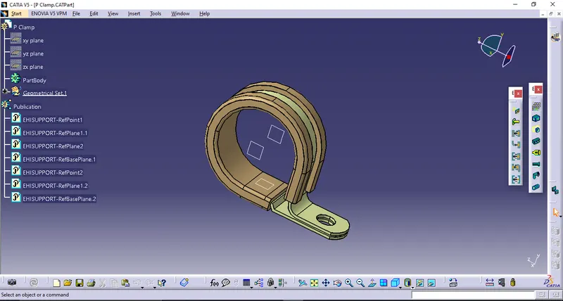
1) Defining P clamp
- after downloading .igs p clamp file open it into catia's part design workbench.
- in order to give the geometrical parameters click on point option available on reference element toolbar>a window will pop up>select point type as 'circle, sphere, elips'>click on any circular edge of the p clamp>a point will appear on the middle of a p clamp on the perticular side which has been selected.
- select the plane option>a window will pop up asking for the plane type and reference>select 'parallel through point' option for plane type>select the circular surface of the p clamp for reference>select the point that has been created earlier. a plane will appear which is parallel to the side of the clamp and coincident with the point.
- to create a point and plane on the other side of the clamp the same two process can be used mention above.
- these geometric parameters was added for the entry and exit sides for routing the wire.
- now its time to create another plane for the base on which the wire will lay on.
- for that select the plane option>a window will appear>select 'offset from plane' for plane type>select the internal flat surface of the clamp for reference>give the offset value accordingly>the base plane will be generate.
- upto this the p clamp is a cad model. it has to be define as an electrical component. for that switch the workbench to electrical part design.
- select 'define support part' option>click on the p clamp>a window will pop up>adjust the orientation of clamp to set entry side for the wire>click on the point of selected side for entry>select the plane for the same>select the plane on the opposite side>select the base plane>ok.
- to define the exit side of the clamp for wire adjust the orientation to select exit side>select 'define support part' option>click on the p clamp>a window will appear>select the point>select plane>the opposite plane has already been selected>select remaining plane for the base.
- in this way the p clamp has been defined geometrically and electrically.
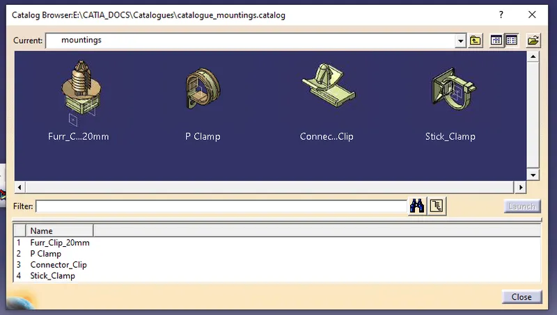
2) catalogue creation for p clamp and other support components
- to create catalogue for support elements go to new>catalogue document>ok>a window will pop up>select add family option>give the family name>select the appropriate type for it>ok>file>save>give name to the catalogue>ok.
- to add the p clamp into the catalogue, opent it in electrical part design workbench>click on store device option>a window will appear>brouse the catalogue which has been created earlier to store support parts>select the family in below option>ok
- the p clamp has been stored in the catalogue.
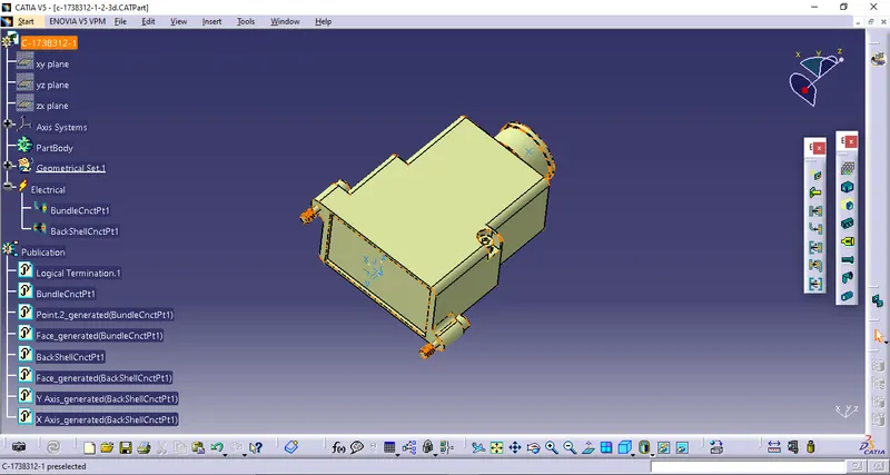
3) Defining backshell
- after downloading the RAR file and extracting it, open it in catia's part design workbench.
- give the geometrical parameters on either sides of the backshell by using point and axis options.
- now switch the workbench to electrical part design>select 'define backshell option'>click on the backshell>a window will appear>give the length in second option if necessary>ok.
- click on 'define backshell connection point'>a window will pop up>identify the backshell connection side and adjust the orientation>select the point for representation>select surface for contact>select y axis for co incidence>select x axis for orientation>ok.
- now change the orientation to bundle connection side>select 'define bundle connection point'>click on the backshell>a window will appear>select surface for representation>select point>select the same surface for initial condition>ok.
- in this way the backshell has been defined.
4) creating the catalogue document to store the backshell
- go to file>new>select 'catalogue document'>ok>a new window will appear>select 'add family' option>give the family name>select suitable type>ok>file>save>give the name to catalogue>ok.
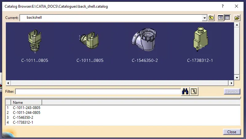
- open the backshell in electrical part design workbench>click on store device>a window will pop up>brouse the catalogue which has created to store the backshell>select it>select the family>ok
- in this way the backshell has been stored in the catalogue.
5) creating corrugated tubes of dirrerent sizes and adding them into a catalogue
- open catia's electrical part design workbench>click on 'define protection part'>a window will appear as given below>give the necessary parameters as mentioned in below window image.
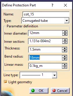
- bend redius should always be 1.5 times the inner diameter>click ok.
- the similar process can be follow to create other tubes having different sizes.
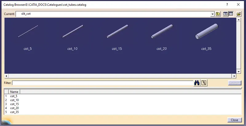
6) creating the catalogue to store the cot tubes into it
- click on file>new>select 'catalogue document'>ok
- a new window will appear, in that window click on 'add family'>give the family name as 'slit_cot'>select the type as 'conduit'>click ok>file>save>give the name to catalogue document>ok
- to store the cot tubes in the catalogue, open the cot tube in electrical part design workbench>click on 'store device' option>a window will pop up>brouse that perticular catalogue and select it>select the family 'slit cot'>ok.
- in this way the other remaining tubes can be added to the catalogue.