Project - 2 - Meshing on the suspension Assembly
Project-2 Meshing on the suspension Assembly
Aim-
- To perform shell and solid mehsing on suspension assembly.
- To deploye connection at required region in that assembly.
Objective-
- To do geometry cleanaup for the component.
- Extract midsurface for the component having thickness less than 5 mm.
- To perform shell mesh (mixed type element) on extracted midsurface according to goiven quality criteria.
- Perform shell mesh of tria element on the surface and then creat volume mesh for the component more than 5 mm thickness.
- Clearing all the failing elements of shell mesh as well as solid mesh.
- Deploying Bolt and seam weld connections at required region in the assembly.
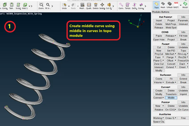
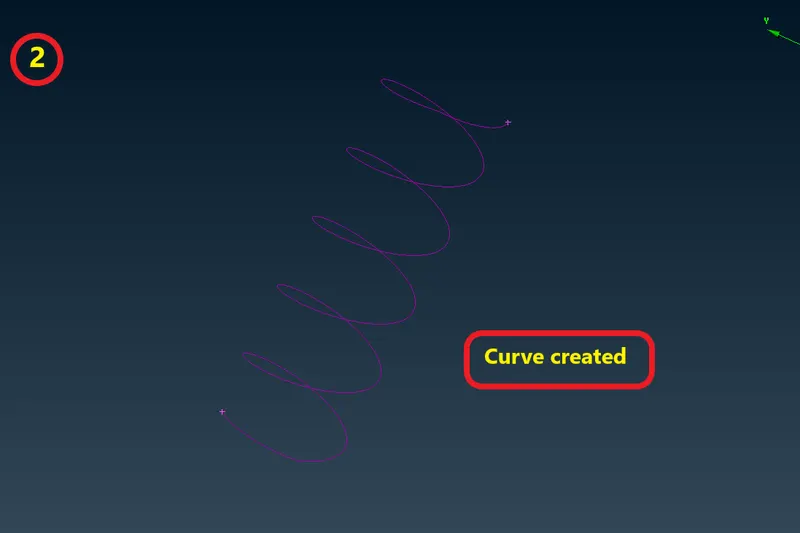
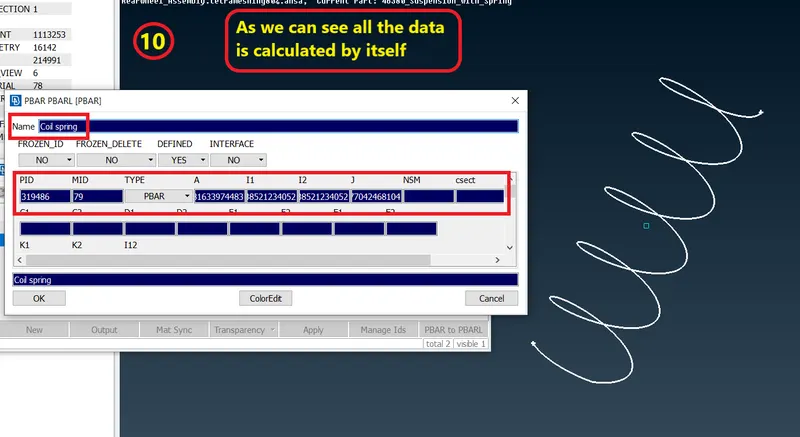
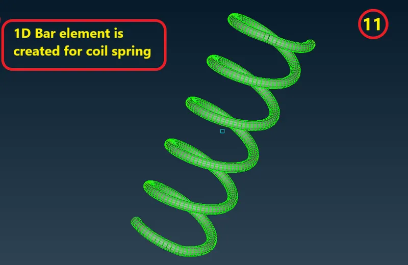
- Model coil spring as CBAR 1D element.
- To perform symmetric operation for creating full visual of sespension assembly.
Theoretical Framework-
Suspension system-
- Suspension is the system of tires, tire air, springs, shock absorbers and linkages that connects a vehicle to its wheels and allows relative motion between the two.
- Suspension systems must support both road holding/handeling and ride quality which are at odds with each other. The tuning of suspensions involves finding the right compromise.
- It is important for the suspension to keep the road wheel in contact with the road surface as much as possible, because all the road or ground forces acting on the vehicle do so through the contact patches of the tires.
- The suspension also protects the vehicle itself and any cargo or luggage from damage and wear. The design of front and rear suspension of a car may be different.
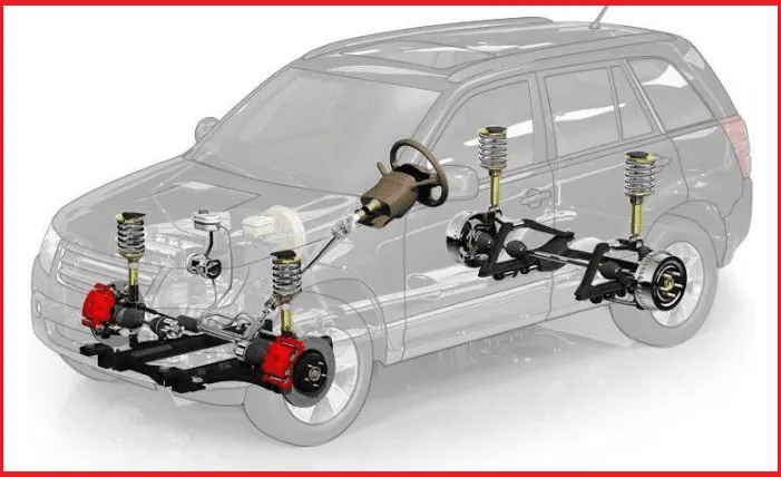
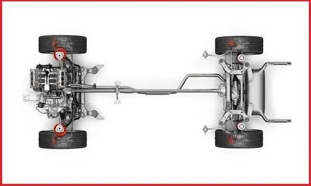
Fig1&2- Suspension system in car
Rear suspension-
- The rear suspension of a vehicle performs the same general function as front suspension, but the specific construction is typically quite different.
- The most basic purposes of a suspension system are to prevent the body of a vehicle from hitting the ground and to keep the tires in contact with the road.
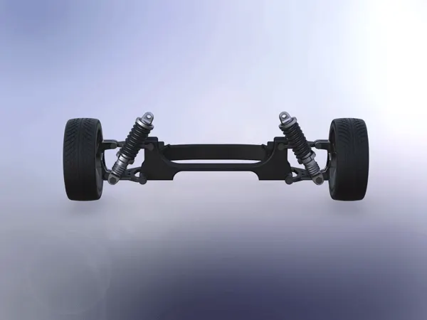
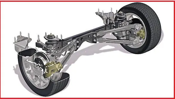
Fig 3&4-Rear suspension
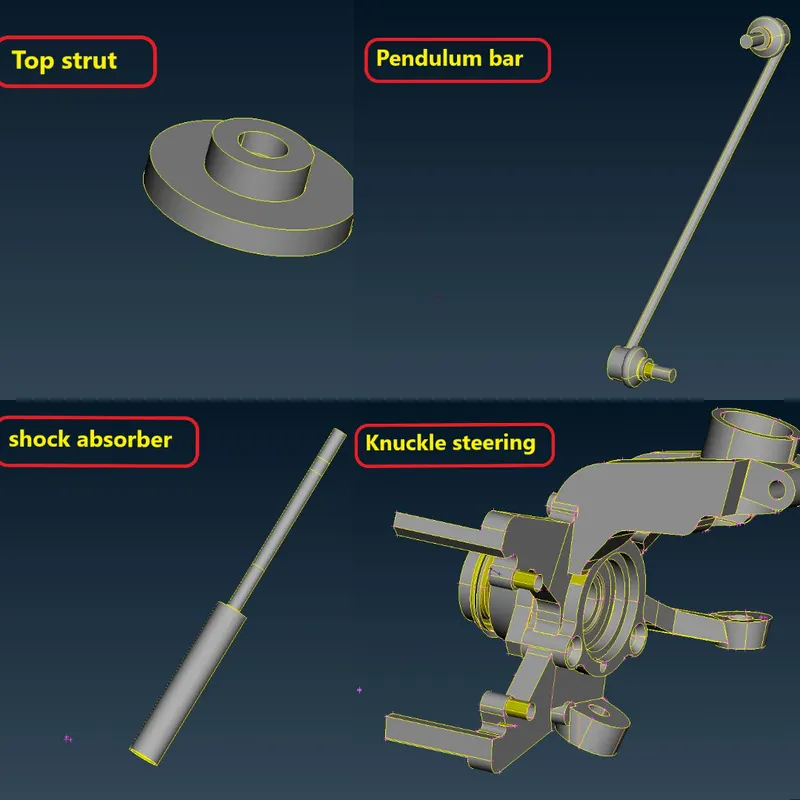
There are Various components in Susupension system-
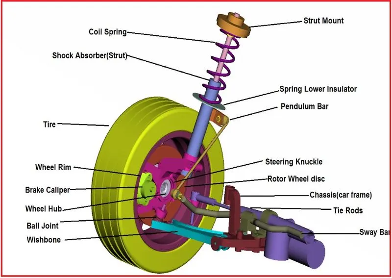
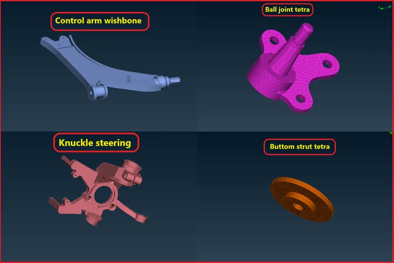
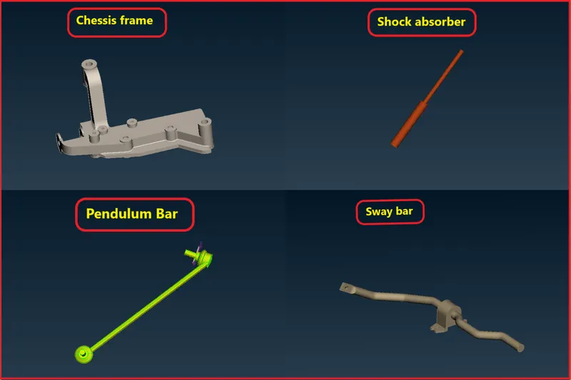
Fig5- components in assembly
Procedure-
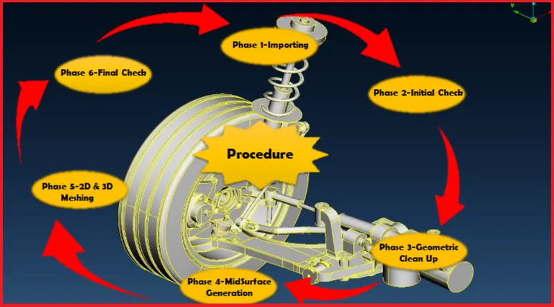
Fig6- Procedure
Stage- 1
Importing the Model-
- Here we will ne importing the CAD file into ANSA.
- Here is many types of file format supported by ANSA for CAD model like IGES,STEP and somtimes Parasolid also depending upon the requirment of industries.
For importing the model
we will go on pull down tab >> File >> open >> select the all format >> select the model from folder
Imported model-
- Hence model is imported on ANSA GUI by following these peocedure.
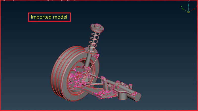
Fig 7- importred model in ANSA GUI
[Note-There are single/free edges on the model which need to get fixed]
Stage-2
Topological cleanup
- Now on this model we will perform geometrical cleanups to eliminate all kind of geometrical errors.
- First we will do topo on the model,
For that, Go to topo module > faces > topo > select the component
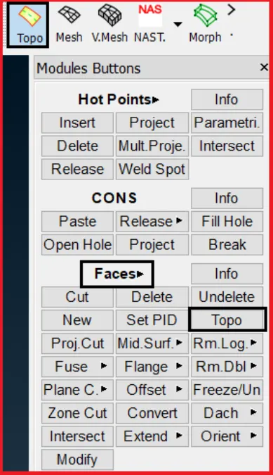
Fig 8- Topo module
After topological cleanup we can see that model is now free from free edges.
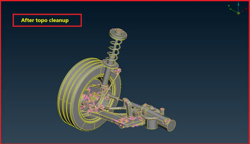
Fig 9- Model after topo
Stage-3
Intial check and Geometry cleanup-
- Now after topological cleanup will to geometric check on this component.
Go to utilities > check > geometry
Click on geometry a new window will popup
- check this as table as shown in figure,
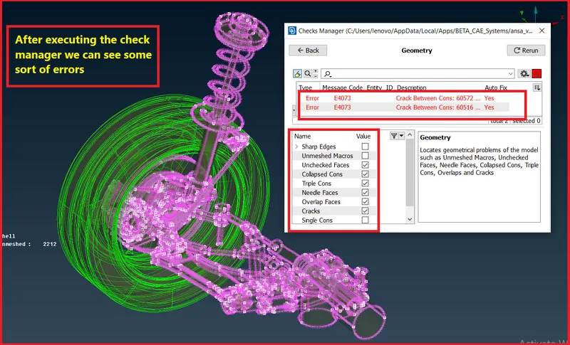
fig10-Model having some geometrical error
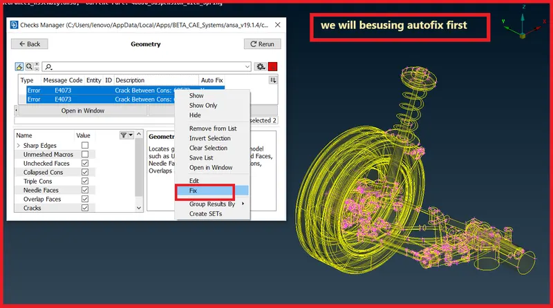
Fig 11- Fixing the issue
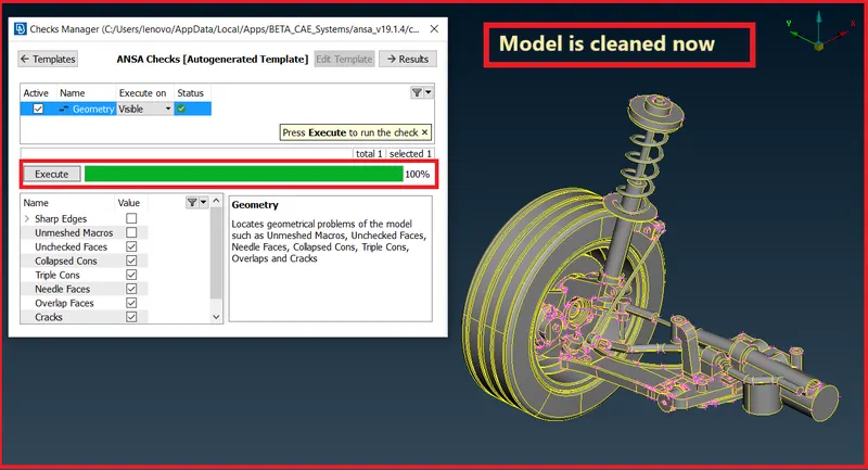
Fig12- Model is cleaned now
Assigning different PID's to the parts-
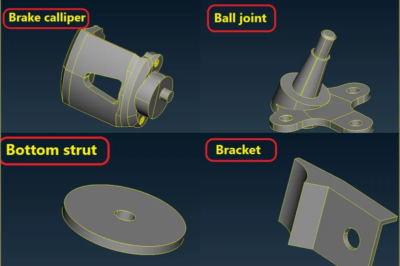
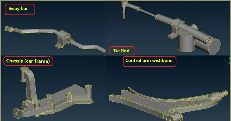
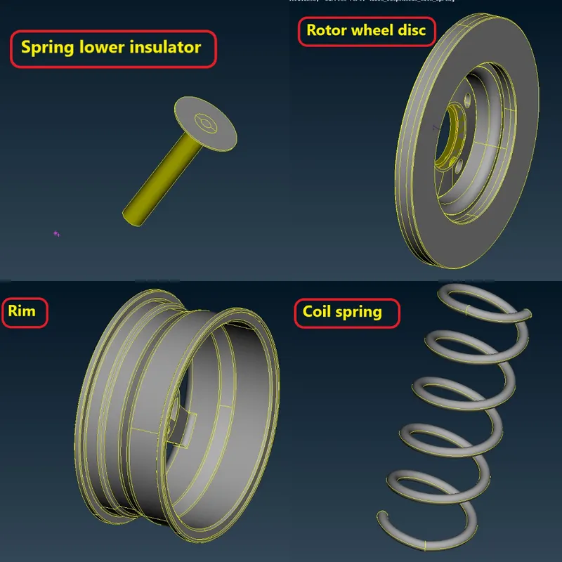
- As we can see there are many components in suspension assembly.
- So we need to create different-2 PID's for ease.
- For creating PID's Go to topo module >> Faces >> set PID.
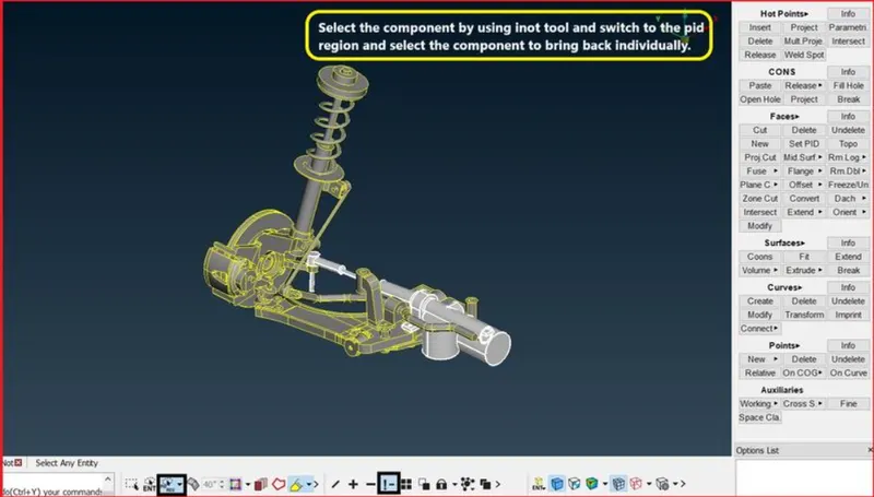
Fig 13- selecting the component
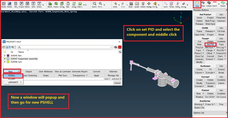
Fig 14 -Creating PID
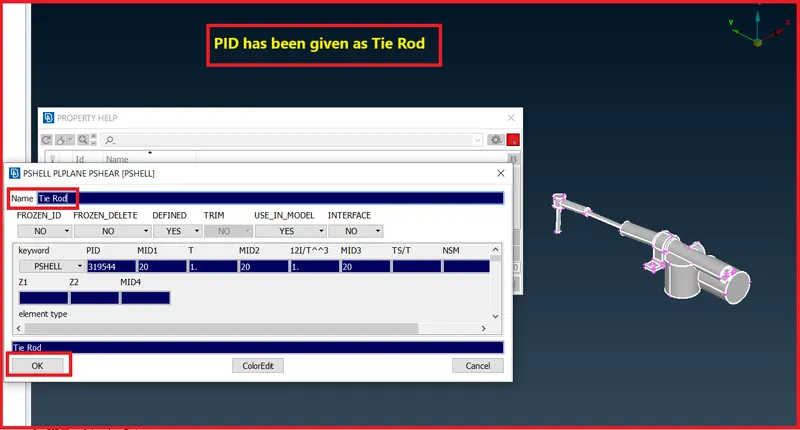
Fig-15 PID's has given as Tie Rod
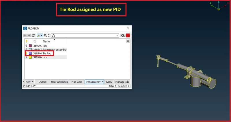
Fig 16- Tie Rod as ne PID
- Now we will do this for all components available in suspension assembly.
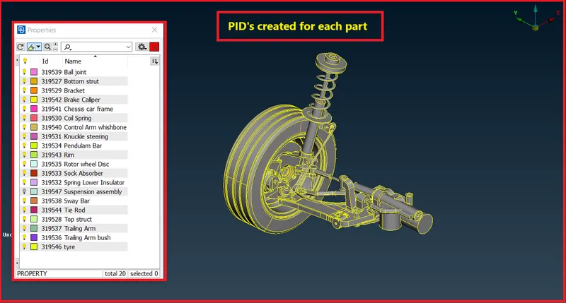
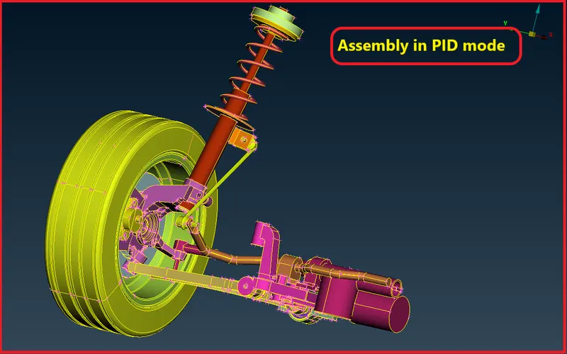
Fig 17- PID's created for all components
Complete assembly-
Stage-4
Midsurface Extraction-
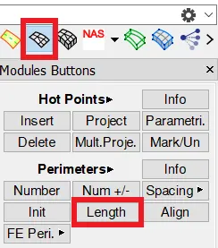
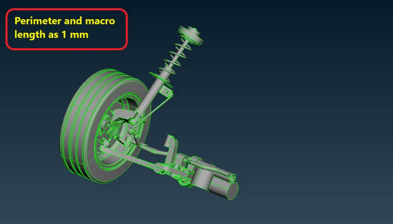
- Before midsurface extraction we will change the perimeter and macros length as 1mm.
- We are doing it just because to get a proper and finished surface while extracting midsurface.
- For giving the perimeter and macros length.
- Go to mesh module >> Length >> perimeter >> select region by box drag >> middle click >> put 1mm
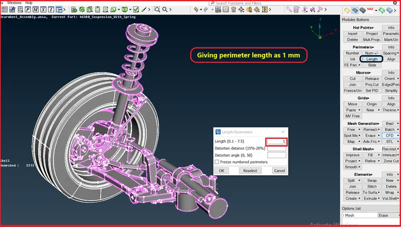
- Simmilarly we will do for macro length also, as 1 mm.
After giving mesh length as 1 mm,
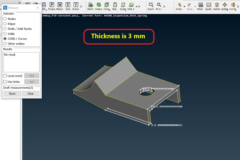
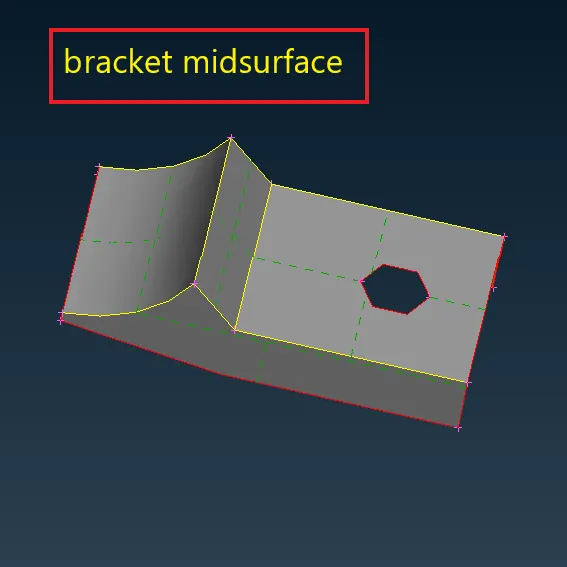
- As we know in this project we only ectract midsurface for the components which having thickness ess than 5 mm.
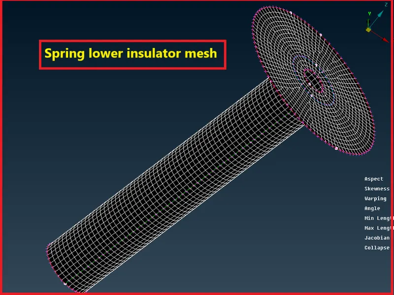
1.Spring lower insulator-
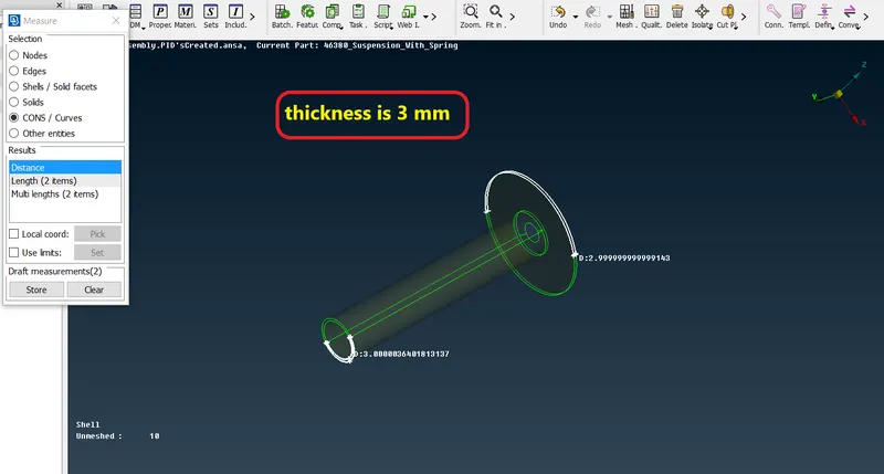
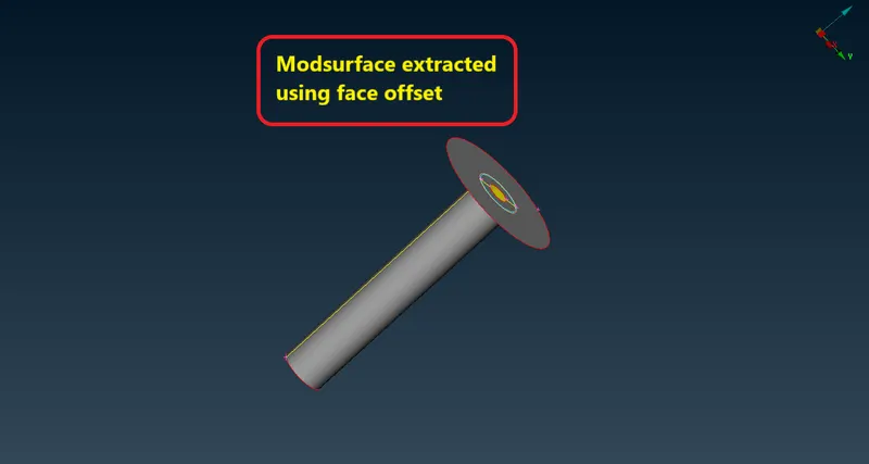
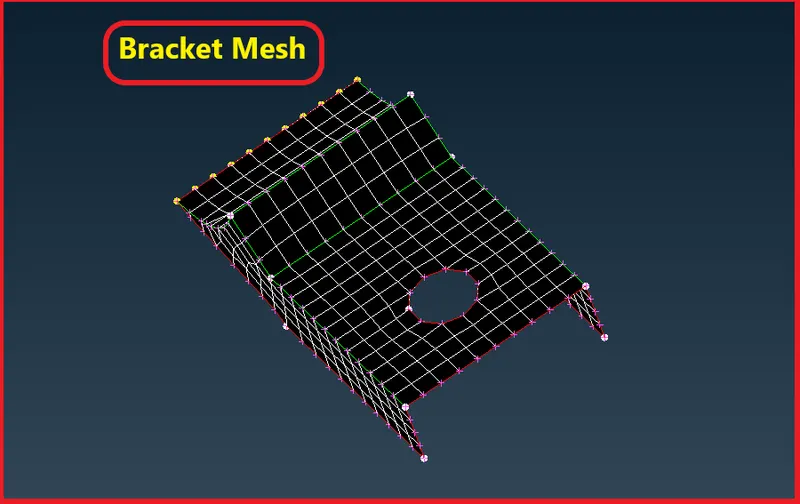
2.Bracket-
Stage-5
2D and 3D Meshing-
2D Meshing-
Once geometry cleanup and midsurface extraction is completed it means there should not be any ustitched surfaces, unwanted free edges etc. Meshing meshing is next step
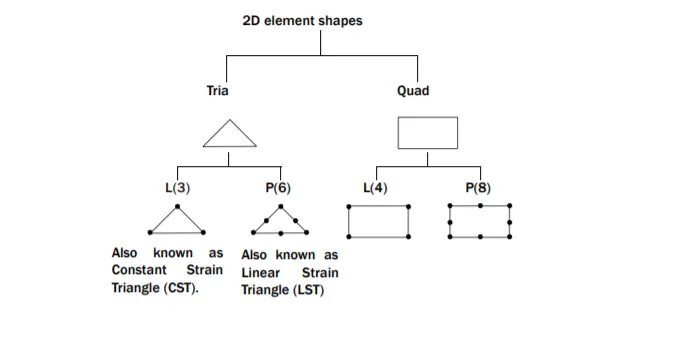
Mesh module >> Mesh generation >> Best >> select component and mesh
- In 2D meshing with ANSA preprocessor easiest way of meshing is by Best mesh option.
- After giving mesh to the surface usually we will be using Reconstruction (Recon.) from shell mesh for better mesh flow.
- Uses of some other tools also like smooth,split,swap,cut,join,projcut etc. For better mesh flow
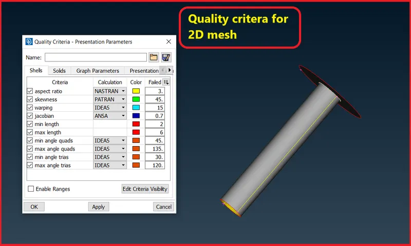
Given Quality criteria for this model for shell meshing:
Target Element Length = 4 Unit
S.N. Quality criteria Functions Values
1 Aspect Ratio Ratio of max lenth/min legth 5
2 Skewness Deviation from ideal shape 45
3 jacobian Transformation of coordinate system 0.7
4 Warping Angle between the two planes of the same element(quad) 15
5 Min.Length shortest length of any given element 2
6 Max.Length largest length of any given element 6
7 Target avg. length Average length of element 4
8 Min. angle quad Minimum angle in any given quad element 45
9 Max. angle quad Maximum angle in any given quad element 135
10 Min. angle tria Minimum angle in any given tria element 30
11 Max. angle tria Maximun agnle in any given tria element 120
12 Tria % percentage of tria in mesh surface 15
- Now we will set the mesh parameter for this 3D mesh as well.
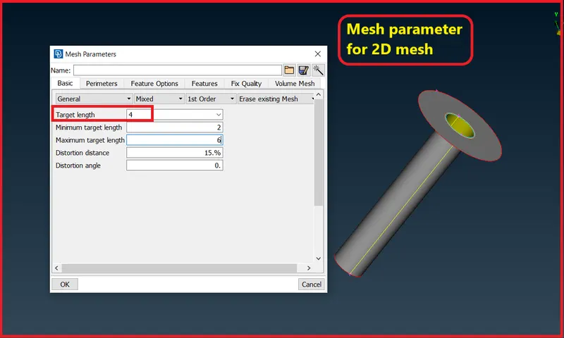
Start meshing,
Some thumbrule while meshing for better mesh flow-
- Feature capturing is must while meshing it means all shared edges should have better nodes connectivity.
- Try to keep less number of trias.
- Avoid trias on feature line and edges should swap it.
- Avoid opposite trias, use split option and combine them.
- Try to keep less number of trias on fillets, use split or swap tool.
- Avoid rotational quads, Recons. or split into trias and move them.
- Use mixed type of elements on complex geometry means trais and quads for this 2D meshig.
3D Solid Meshing-
- A 3D mesh consist of finite elements with each element define with specific physical propreties.
- This 3D mesh is used for ananlysis, in various domains such as static structural analysis, dynamic model analysis, thermodynamic ananlysis etc.
- Any 3D modelled obejct with specific volume and dimension can be mehsed with thw finite no of elements that helps in solving for accuracy in pin pointing regions of strain at a higher resolution.
- We wil do 3D mesh for the components, thickness more thatn 8mm.
- Before generating the mesh give the quality criteria and mesh parameters.
Types of grid in 3D Meshing
1.Structured grid
Structured are identified by regular connectivity. The possible element choices are quadrilateral in 2D and hexahedra in 3D. This model is highly space efficient, since the neighbourhood relationships are defined by storage arrangement. Some other advantages of structured grid over unstructured are better convergence and higher resolution.
Advantage-
- Memory Efficient
- Fast to solve
Disadvantage-
- Angled or curved geometries are approximated (Leads to stair stepping)
2.Unstructured grids
An unstructured is identified by irregular connectivity. It cannot easily be expressed as a two-dimensional or three-dimensional array in computer memory. This allows for any possible element that a solver might be able to use. Compared to structured meshes, this model can be highly space inefficient since it calls for explicit storage of neighborhood relationships. These grids typically employ triangles in 2D and tetrahedral in 3D.
Advantage-
- Complex geometry easy to mesh
- Arbitary positions
Disadvantage-
- Greater memory requirment
- Slower to solve
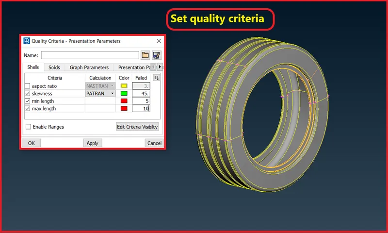
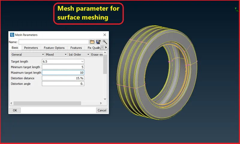
Quality Criteria for Surface Meshing of Tyre and Rim (Element type: Tria) :
Before meshing we will set all the quality criteria and mesh parameter. For this particular component we will set only maximum and minimum length for 2D mesh.
S.No Quality Criteria Value
1. Target/Average length 6.5
2. Minimum Length 5
3. Maximum Length 10
4. Skewness 45
3D Meshing of Tire and Rim-
Set Perimeter and Macros length-
- Before meshing we should provide perimeter and macros length for better element capturing.
- Will set the perimeter and macros length according to average element length.
Go to mesh panel > Perimeter > Length > Perimeter(1) ,macros(1)
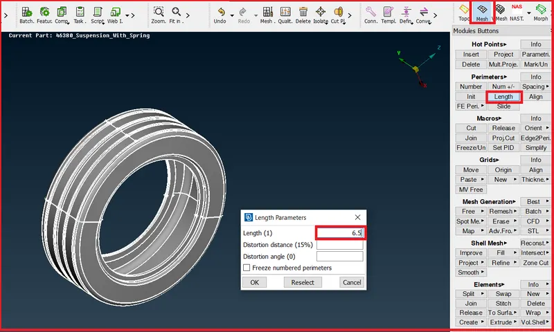
- Simmilarly we will do for macro length also.
Start meshing(surface meshing)
For meshing this component we will go to,
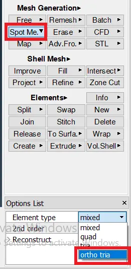
Mesh module > Mesh generation > Spot mesh (ortho mesh) > select component
As we can see here maximum surface portion of this spherical bearing is curved so for curved surface we will provide ortho trias
And on flat region we will use normal trias, which we can switch from here,
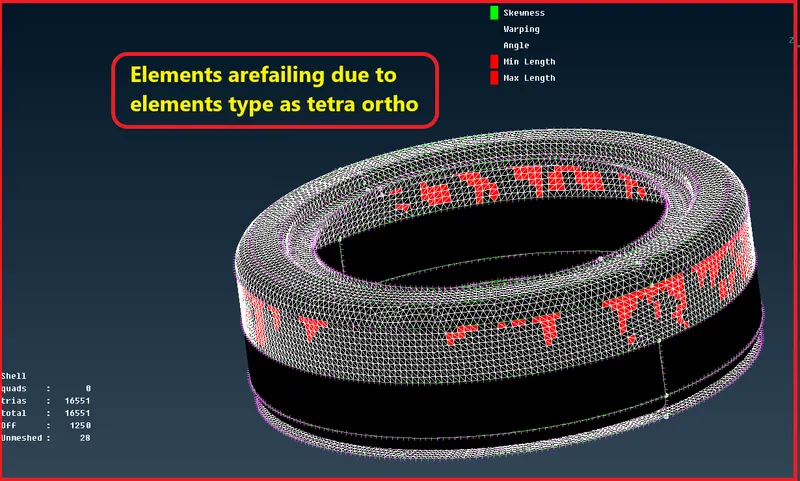
- Here element is failing due to average element length size is 6.5 mm.
- So now we will try to reconstruct it as tria element.
Go to mesh module>> shell mesh >> reconstruct >> element type as tria
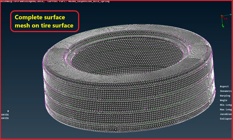
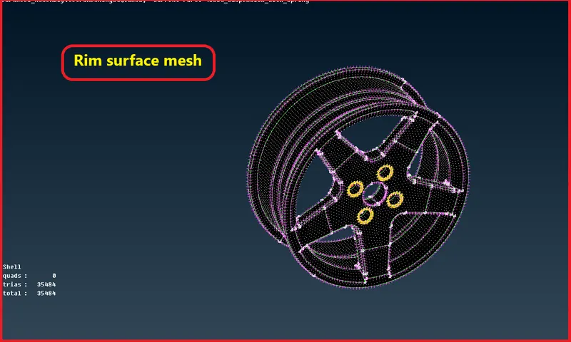
- Now after 2D mesh on surface we will convert it into volume mesh.
- Go to volume mesh module > Define > Manual > Window selection > Creat new PSolid
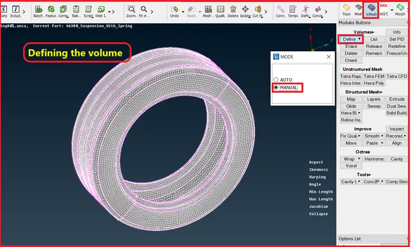
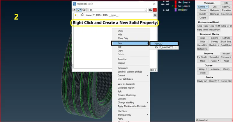
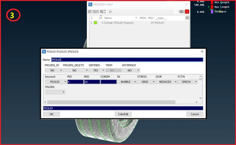
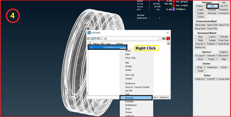
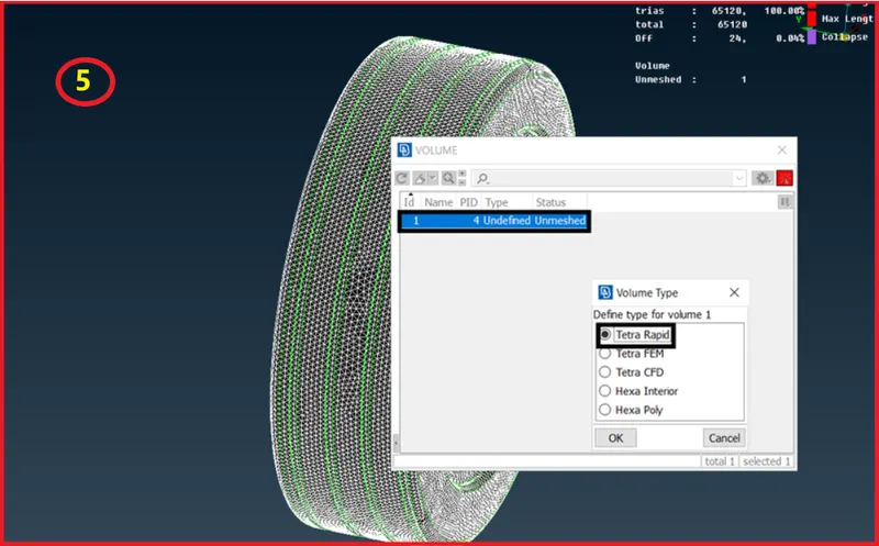
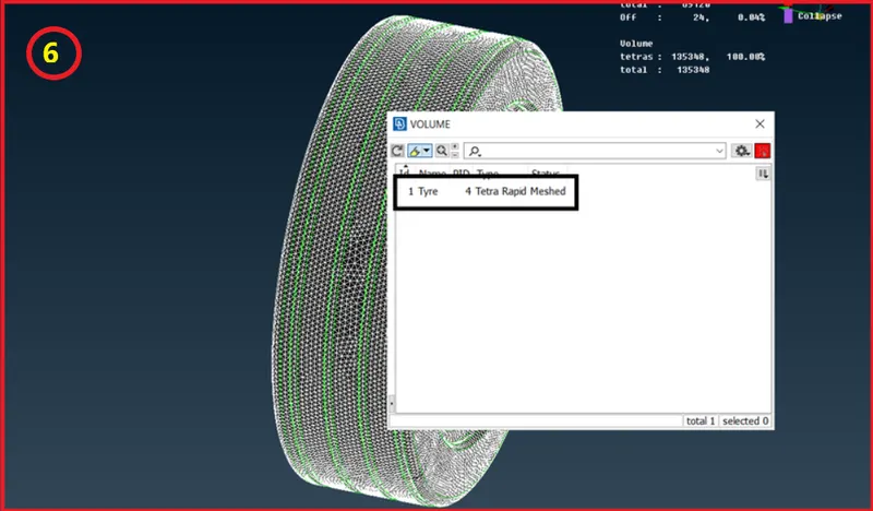
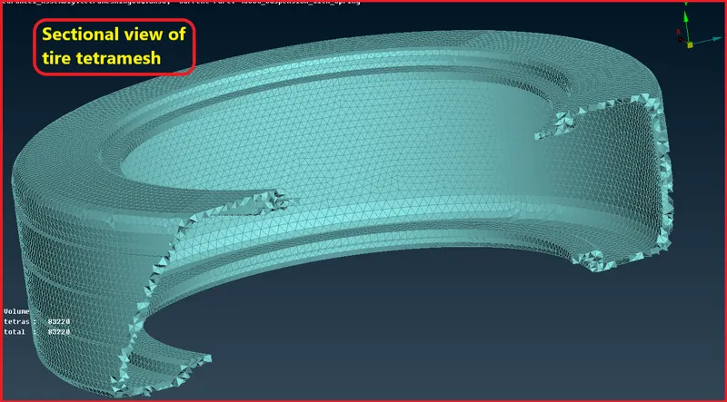
- Now simmilarly we will do for rim as well.
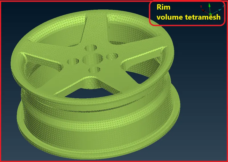
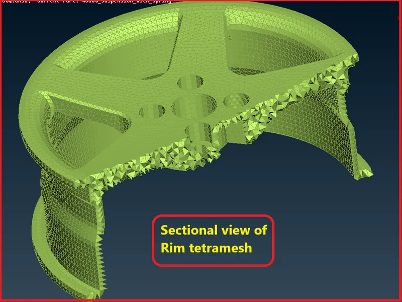
Checking for Tet collapse-
Tet collapse is one of the quality parameters, which will be checked while generating Tetrahedral elements. It can be calculated by measuring the distance of a node from the opposite face, then each of the four values will be divided by the Square root of the opposite face's area.
Tetra elements whoes collaps value fall below the value specified are highlighted when the tetra collps function is selected these elements remains highlighted untill the check elements panel is existed.
- In 2D tria mesh we generally check for failure of max and minimum length of element.
- In 3D tetramesh we generally check for tet collapse in the tetra element.
Set the quality criteria for tet collaps,
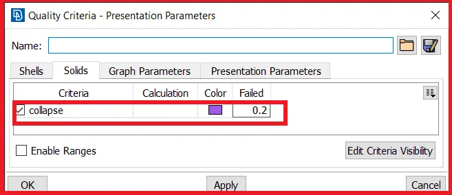
Now apply this quality over tetramesh,
- After applying the quality if we found any failure then will go for cleanup.
- In cleanup we mostly use MVFree from Grids.
- Using MvFree we can fix the issue by adjusting the edges of elements.
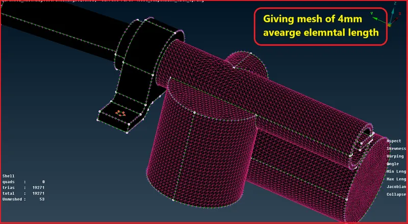
Quality criteria for Surface Meshing of Non Uniform thickness components other than Tyre and Rim (Element type: Tria)
S.No Quality Criteria Value
1. Target/Average length 4
2. Minimum Length 2
3. Maximum Length 6
4. Skewness 45
- There is new quality criteria for component except tire and rim.
Before meshing we will give the perimeter and macro length as 4 mm because the average element length is 4 mm for these components.
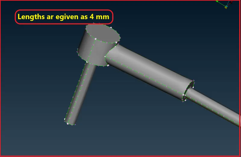
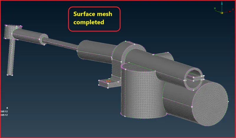
So now we will start meshing those components.
start with Tie Rod,
- Now we will follow the same procedure for defining volume and creating volume mesh as did it earlier.
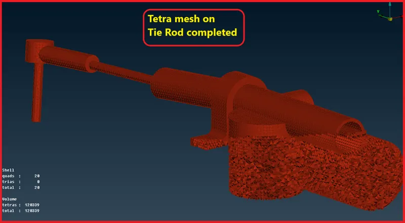
Solid Mesh of all components-
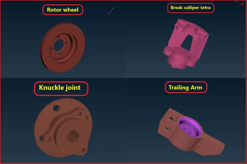
Modeling coil spring-
Representing coil spring as 1D Bar element-
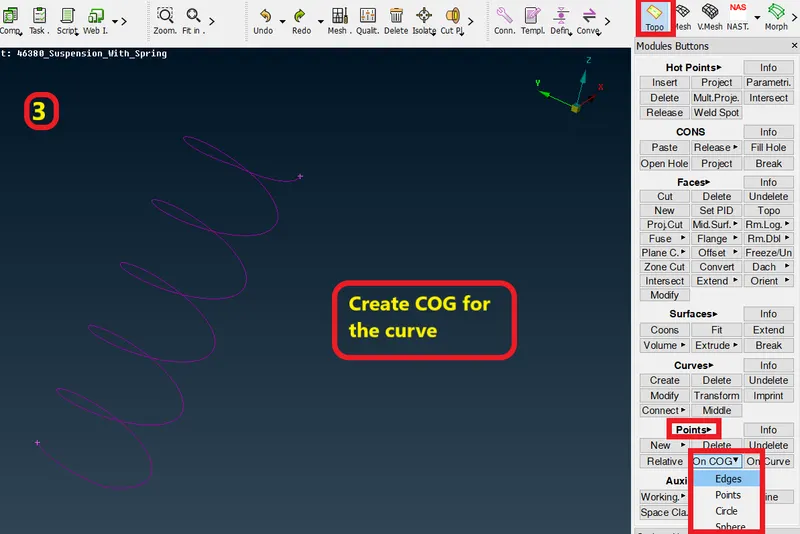
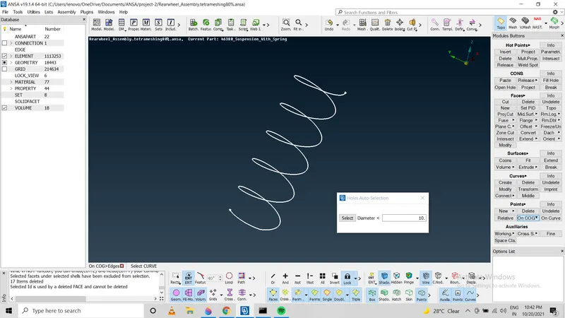
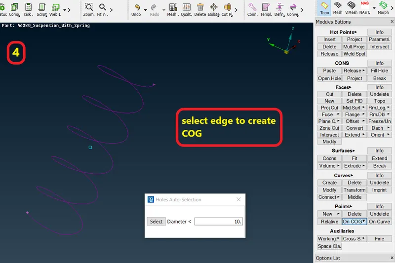
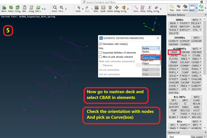
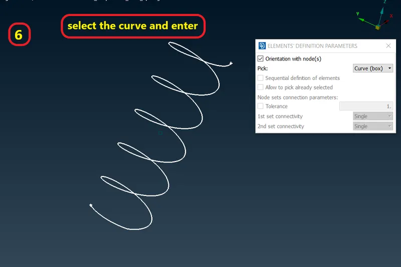
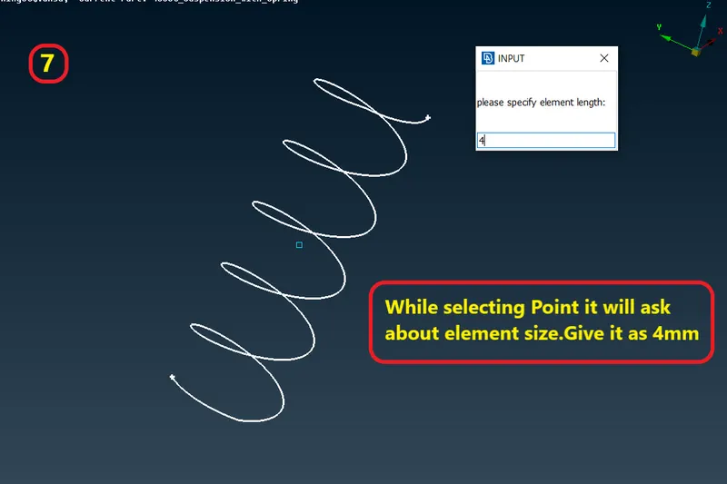
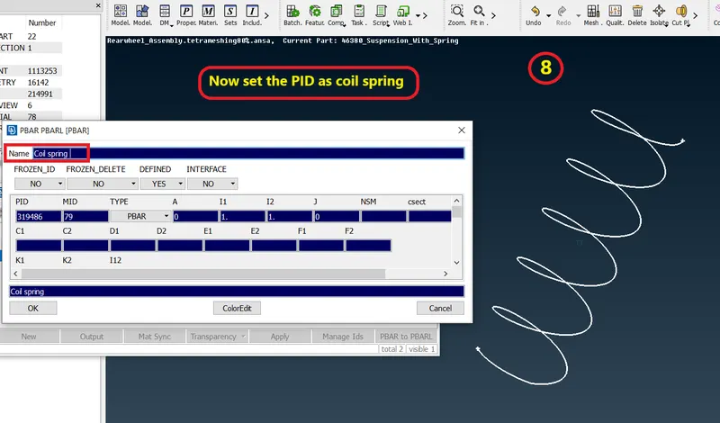
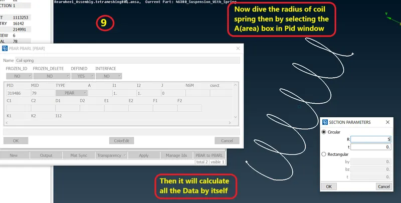
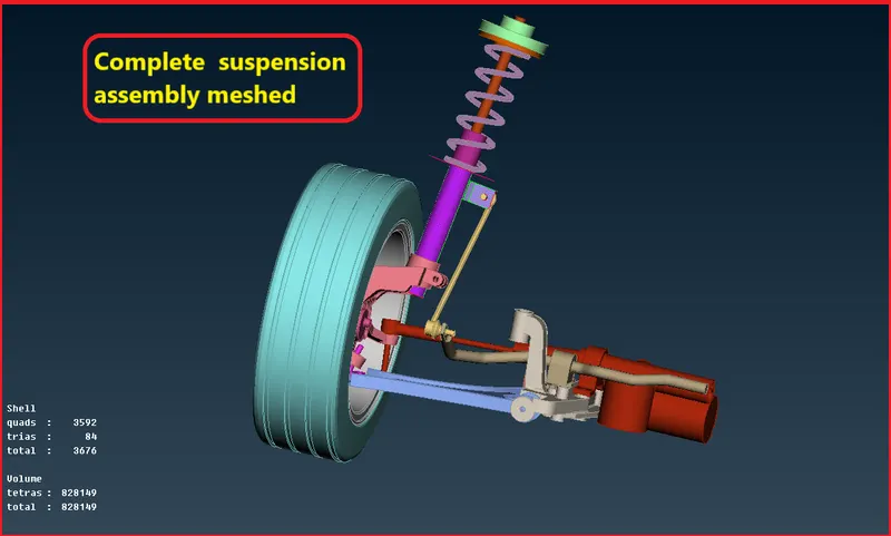
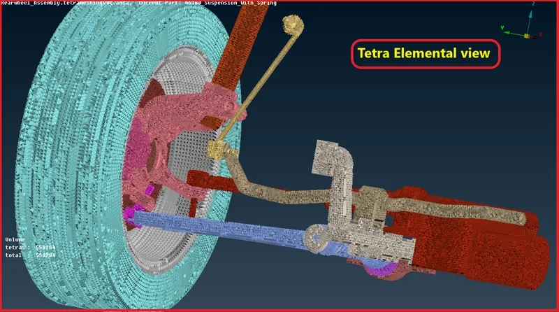
After integerating all the components of suspension assembly-
Stage 6-
Deploying connections-
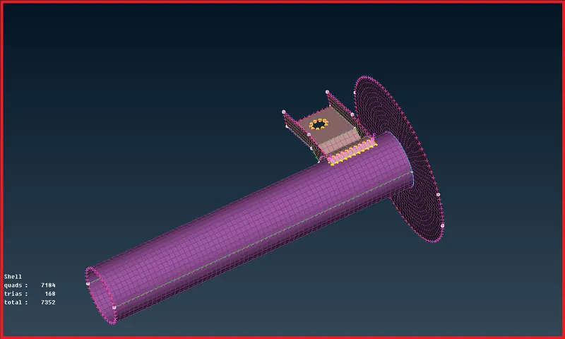
- As in this project 2 we will majorly uses the RBE2 connection.
- It will be of bolt type,cluster type and RBE2 Rigid at pin locations.
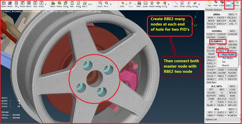
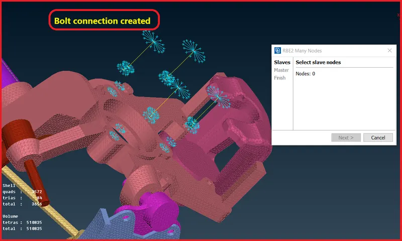
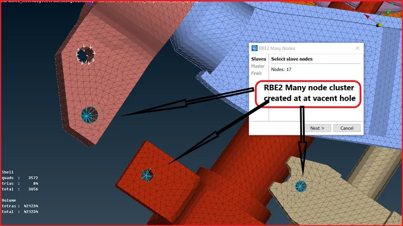
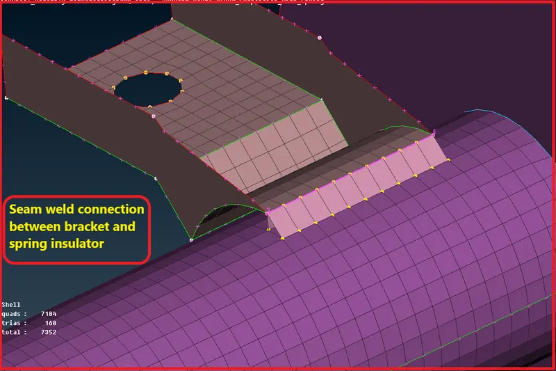
- We will also use seam weld connection at the location of bracket connection to spring lower insulator.
- Create curve using cornstocurve and then convert those curves to seam line convert tool.
- bThen open task manager and click to seam line and the enter a window will popup where fill all the details required for seam connection like search distance and width and surfaces which need to connect etc.
- Then appply and realize the connection.
Stage-7
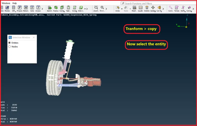
Now Go for symmetry of the model-
- For creating symmetry we will go for transform > copy option in module tab.
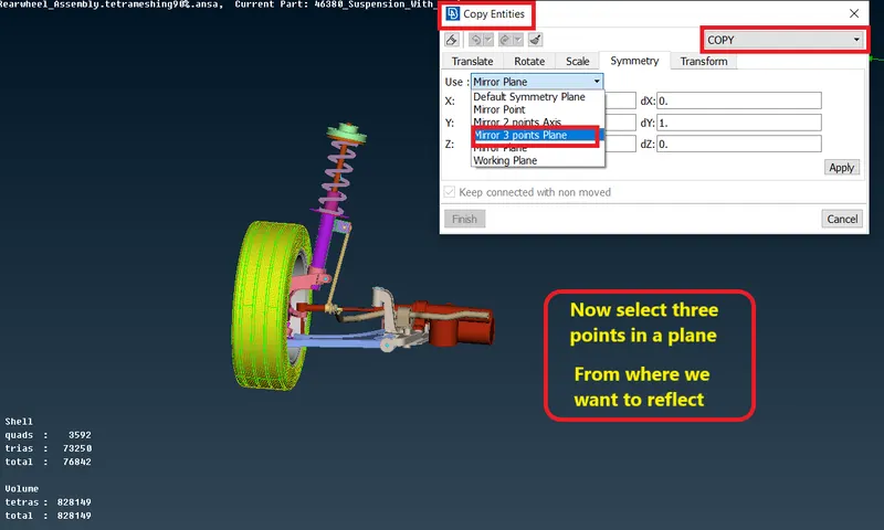
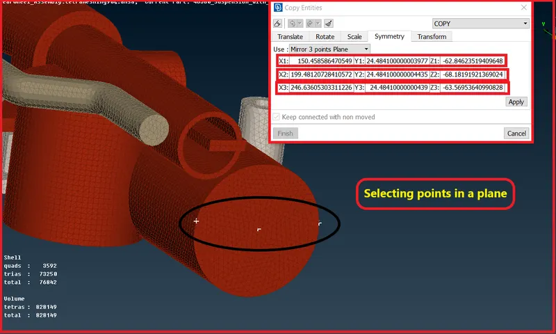
Now click on FINISH,
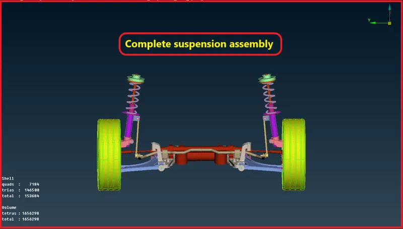
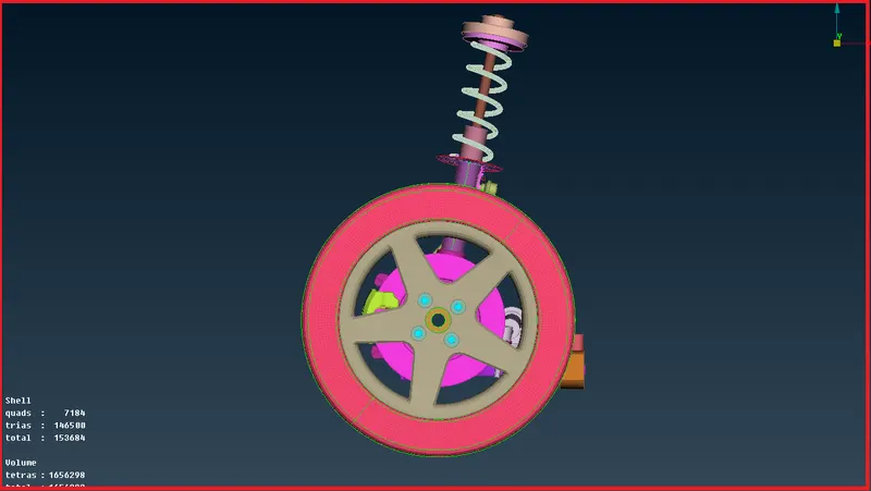
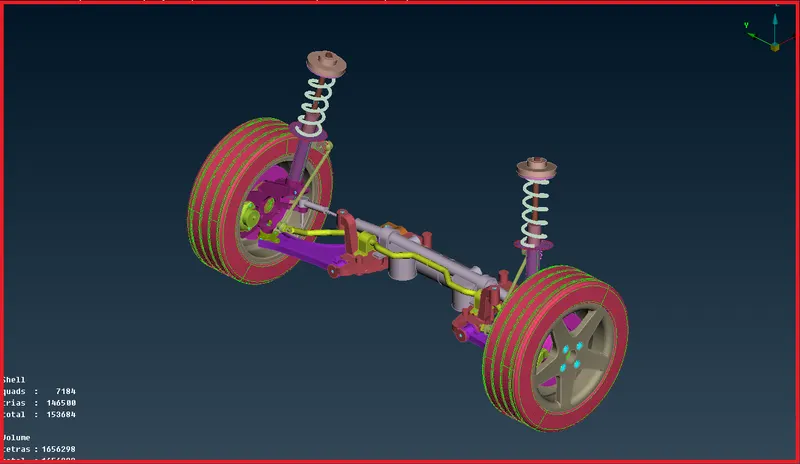
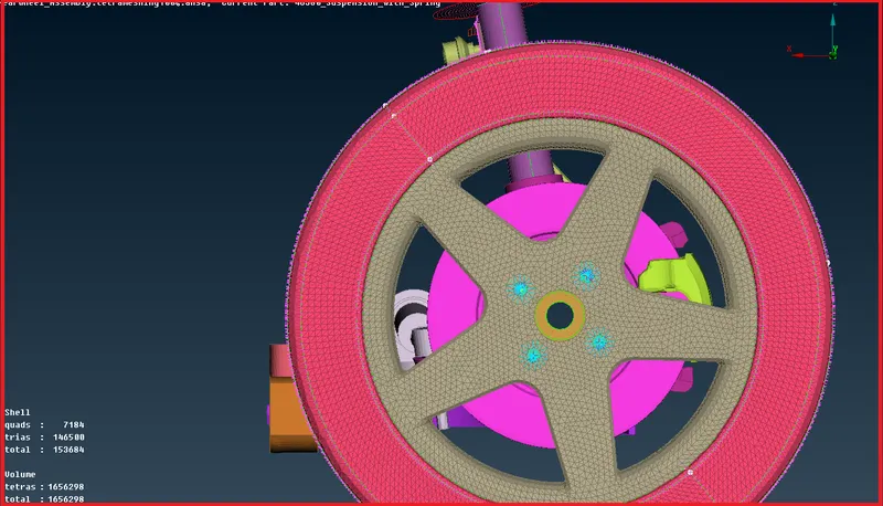
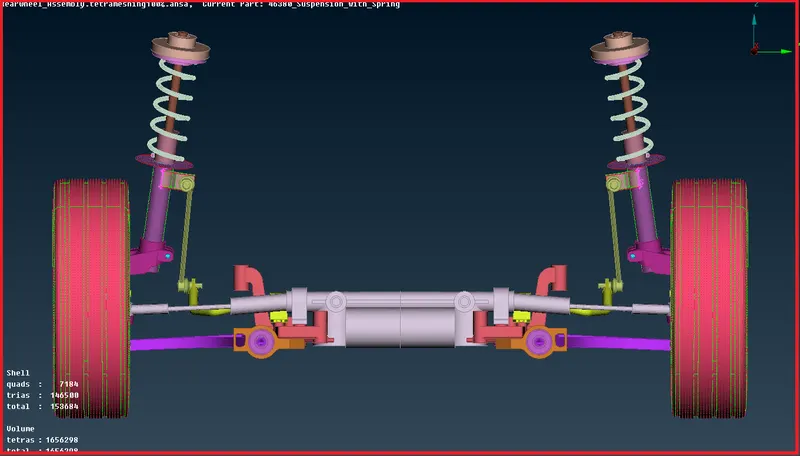
Final model in different-2 View:
Result-
- Geometry cleaned and PID's assinged.
- Hence no surface deformation and glitch are found in the assembly.
- Performed 2D mesh and assign thicknesson bracket and spring insulator.
- Performed 2D mesh and convert it into 3D tetra mesh by defining volume.
- Achived proper mesh flow with zero elemental failure.
- All required connection has been deployed.
- performed Symmetry for achiving complete rear suspension assembly.
Learning Outcome-
In this project-2 rear suspension assembly i came to know,
- 2D shell meshing on midsurface of components having less than 5 mm thickness.
- 2D tria shell meshing on surfaces and then creating 3D Solid tetra mesh for the volume.
- How to create proper mesh flow without kink,raises and dents.
- How to clear elements failing for tet collaps.
- Deploying connection of RBE2 and seam weld.
- Symmetry operation for Rear suspension assembly.
Final Model Link-
https://drive.google.com/file/d/1uSXYKsiGMZL7DK90_zfFlECFn3_k1fuq/view?usp=sharing