Assignment 2-RADIOSS Engine File Editing & 3D Meshing Challenge
Aim-
- To calculate the values asked, and edit engine file according to the values.
- To perform solid meshing on housing model and arm bracket model.
Objective-
- To calculate the speed of sound in rail material.
- To calculate time taken for shock wave to travel through the rail.
- To put all the calculated value and edit engine file.
- To perform shell meshing on housing surface and volume meshing with tetra elements.
- To perform hexa mesh on arm bracket model.
- To clear all the elements failing from tet-collaps.
Procedure-
Step-1:
Calculate all the values and edit engine file
Question 1- Check the material properties of the rail component and calculate the speed of sound in steel rail.
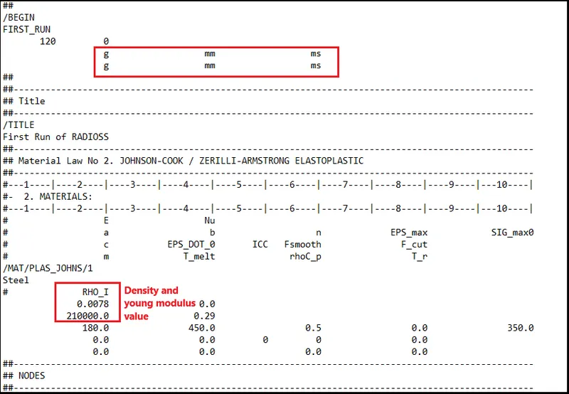
- From here we can check the density and young modulus value which helps in calculating C value i.e. speed of sound in the material.
Formula is, c=underroot(rho/E)
c=underroot(0.0078/21000) units [(g/mm^3)/(N/mm^2)] =mm/ms
=5188.78 mm/ms
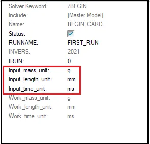
[Note- Here we will do calculation according to the units given by solver.]
Question 2.The length of the rail is about 1000 mm.calculate the time takes for a shock wave to travel from one end of the rail to the other.
Length of rail given as =1000mm
so,
Time taken to travel shock wave through the rail =(Length of rail)/(speed of shock wave htrough the rail)
t= 1000 / 5188.78 (mm)/(mm/ms)
t = 0.1927 ms
Question 3- Calculate time for sound to travel length of rail.
Since, Speed of sound throught rail = Speed of shock wave through rail
Time taken for sound wave to travel through rail = time taken for shock wave to travel through rail
So, Time taken for sound wave to travel through rail= 0.1927 ms
Question 4- Edit the engine file so that the stress wave can be monitored, moving from one end of the rail to the other during impact -this will require a termination time equal to the time it takes for the sound to travel the length of the rail(set on/RUN card).
In radioss solver for every simulation we have two kind of file,
- Starter file
- Engine File
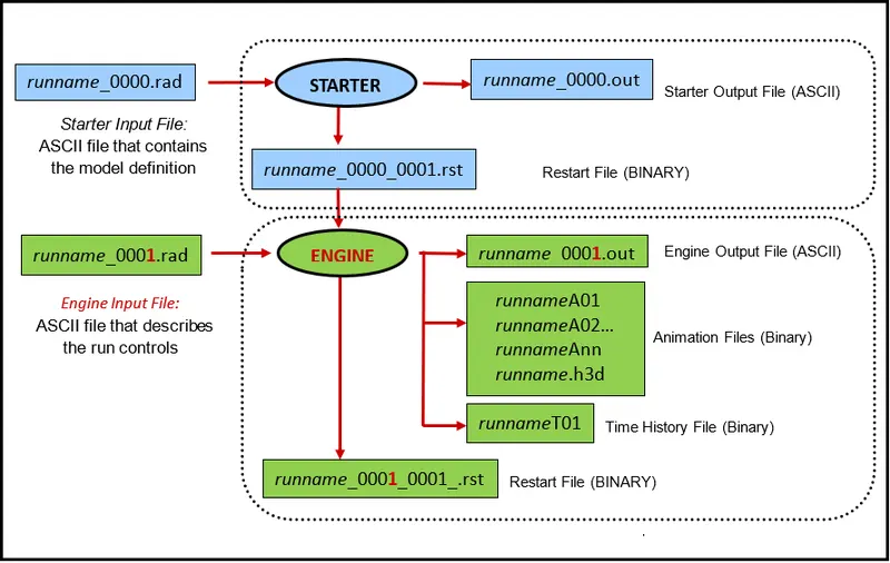
- The starter file contains the model definition like units, matrial and properties, nodal information, boundary condition, interfaces, load collectors geometrical information etc. The radioss input file name is runname_0000.rad and the listing file name is runname_0000.out
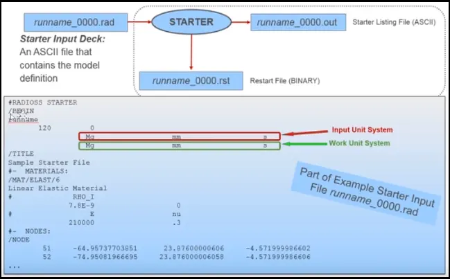
- The engine file describes the run control. It controls the simulation speed and contains informations about the software version, the run time, time history files and animation controls etc.The radioss engine input file name is runname_0001.rad and the listing file name is runname_0001.out.
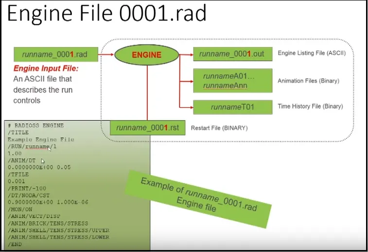
[Note- Engine and starter file can also be combined into single input file utilizing merge starter and engine file in export panel]
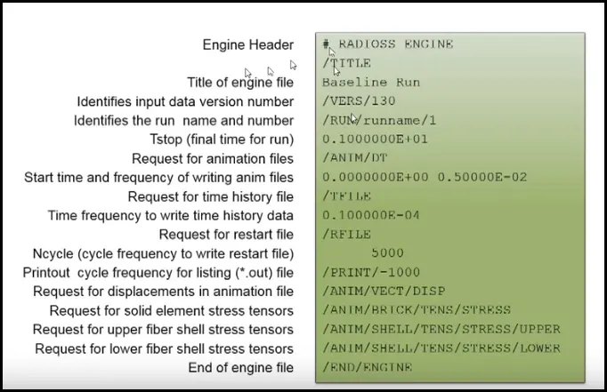
Engine File Edit-
Procedure-
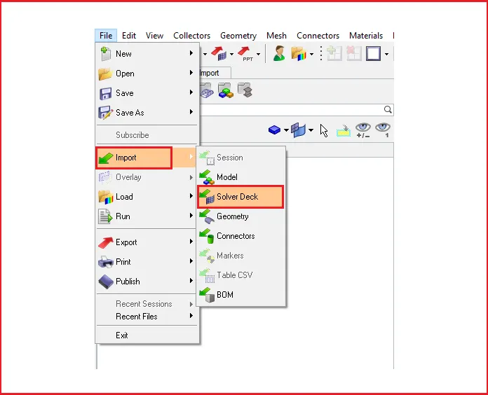
- First we will import the starter file in radioss block.
Go to standard panel > Import > Import solver deck
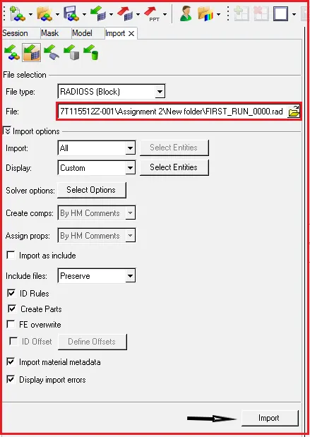
- After selecting solver deck select the runname_0000.rad file from drive location.
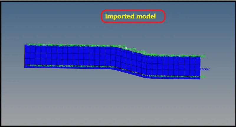
- Now after importing the model we have to check for control cards in the model browser.
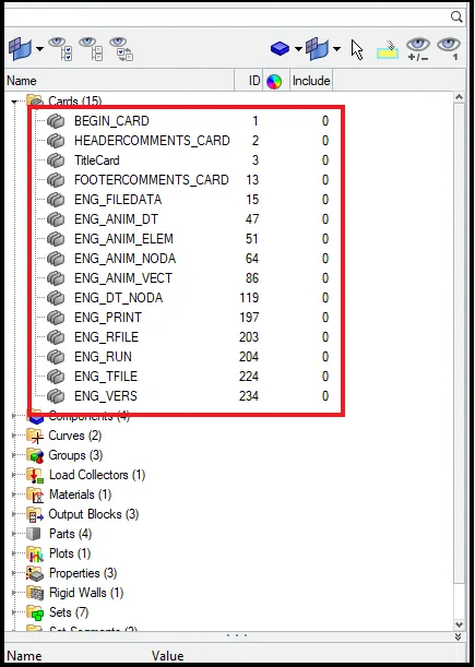
- As we can see there is all control cards available in the model.
- These are the control cards in which we will fill the calculated values..
- There are mainly two cards in which we have to fill the calculated value i.e. ENG_ANIM_DT and ENG_RUN.
Question 4(Continued)-
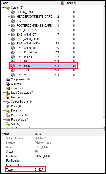
- Now in order to get value of time step as 0.1927 because it is the termination time only.
- Click on ENG_RUN card and enter the value.
Question 5- Set the frequency of animation output to a time that will give 20 animation steps(/ANIM/DT).
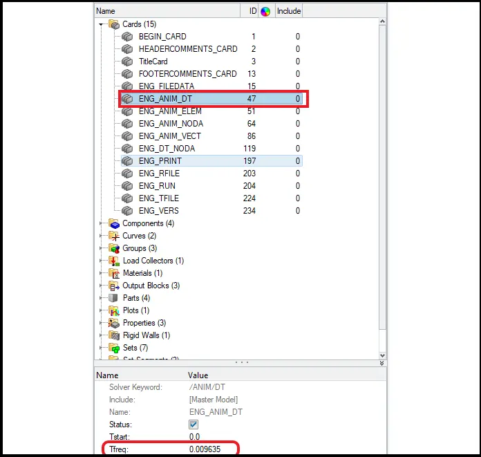
Tfreq=Run time/no of steps
= 0.1927/20
Tfreq=0.009635 ms
- Now we will feed this value in ENG_ANIM_DT card.
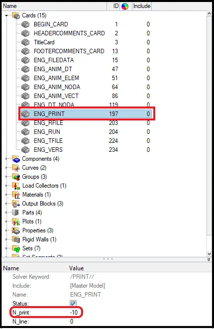
Question6. Change /print -10.
- Now we will open ENG_PRINT card and change the print number as -10.
- Now after assigning all the values in cards, we will go for run the solver.
- Fo that Go to Analysis panel > Radioss > select input file > Radioss.


- After selecting the input file run the solver, click om radioss.
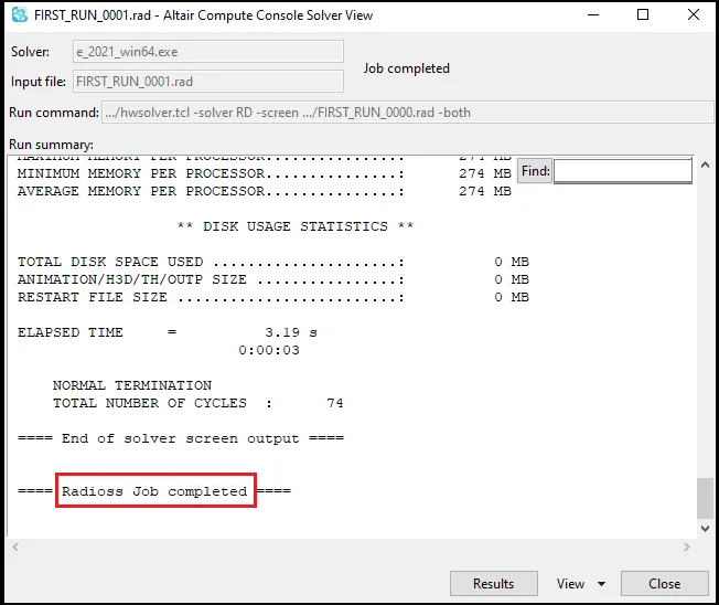
- Radioss popup a indivisual window in which it will show job completed as shown below.
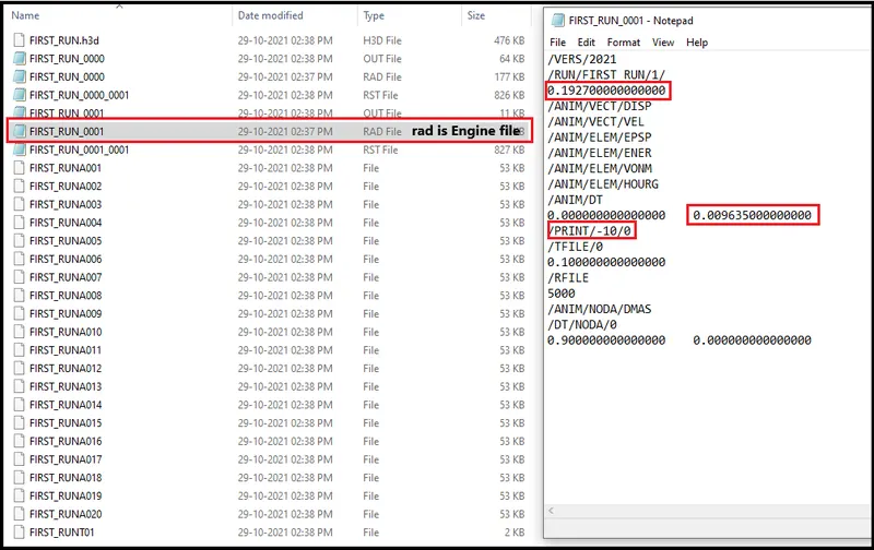
- Now after radioss job done go and check for the engine file that it is edited according to the values he have puted or not.
- Go to file location is saved while radioss run.
- Now we can see all the edited values will show here.
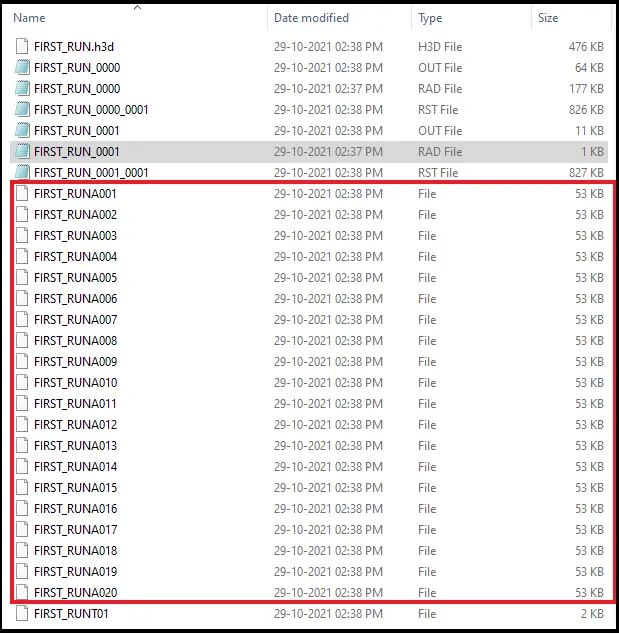
- And now as we entered Frequency value as 0.009635 to get 20 animations.
- So now we can see that all 20 animation file have been created.
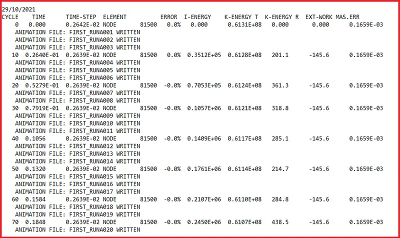
- Now we can see in OUT file there are 3 indivisual animation files are created in each cycle as shown below.
Question 7. 3d meshing tetra mesh and hex mesh.
Procedure-
Stage-1: Importing CAD
- Since we are importing the CAD file model in this challenge.
- So there are many type of file like IGES,STEP and parasolid we can use if we are importing a file into any CAD and CAE software.
But here in hypermesh we can use only three kind of file format:
- IGES(Initial Graphics Exchange Specification).
- STEP ( Standard for the Exchange of Product Model Data).
- SolidWorks.
Now these time most of the industries started working parasolid file formate also.
[Note: While importing the file into graphical user interface be sure that whether the file is .step or .iges file. Otherwise we will face difficulty during importing the model.]
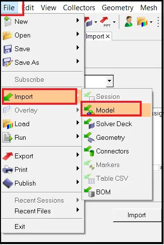
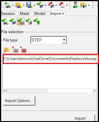
Tool we use to import in the way: File >> Import >> Import Model >> File type >> Open File.(As shown in below picture)
- Imported model
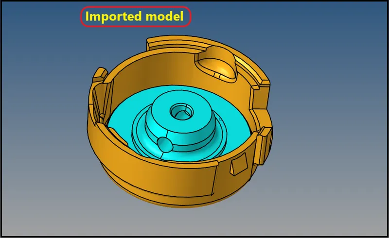
- As we can see there is two different component in model browser.
- So we will work seperately on these two models.
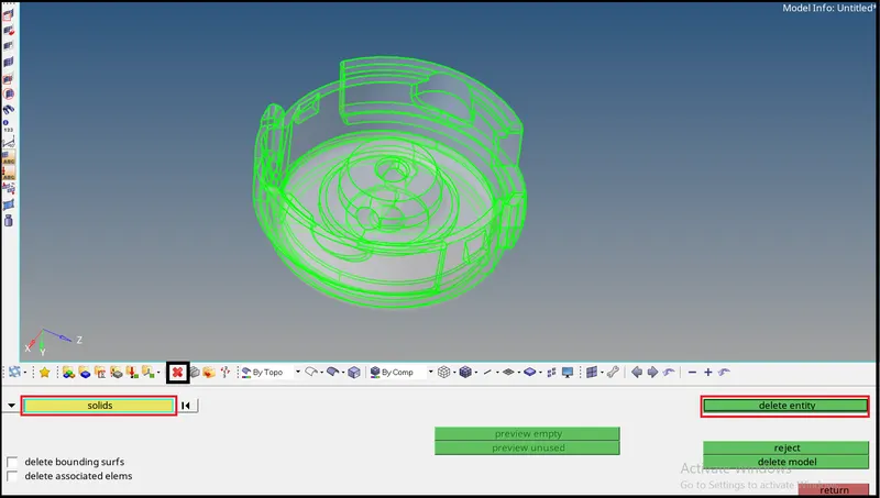
Delete solid-

Stage 2- Geometry cleanup :
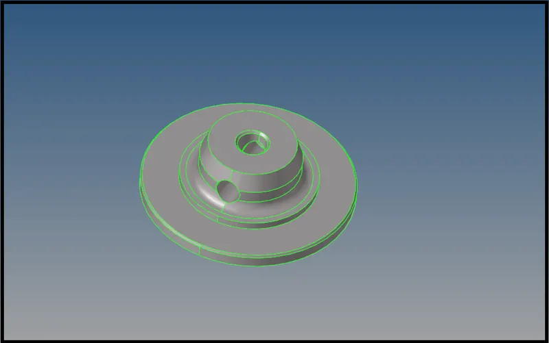
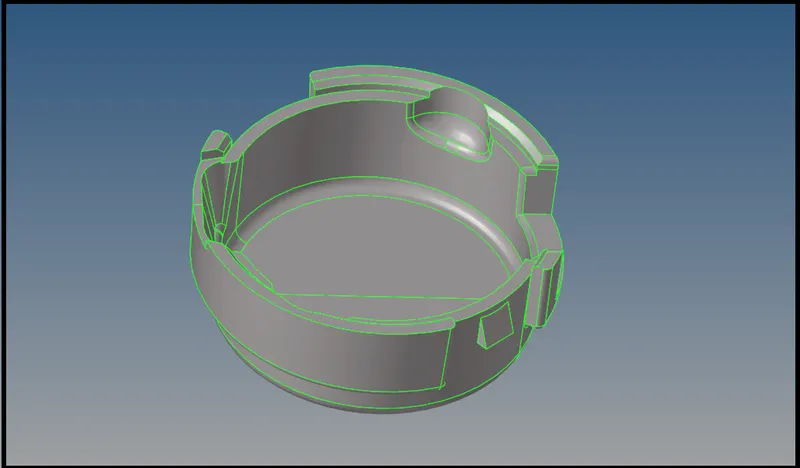
So after importing the model we will go for check the model for any geometrical glitch lik,
- Unnecessary surfaces.
- Free edges.
- Damaged geometry.
- Unwanted connection between surfaces.
Stage-3
Creating 3D shell element on surface-
- For that go for automesh in 2D and select element type as tria.
- And also set the quality criteria as required for this challenge.
- Go to 2D > automesh > surface > displayed > element size 5 > mesh type as tria.
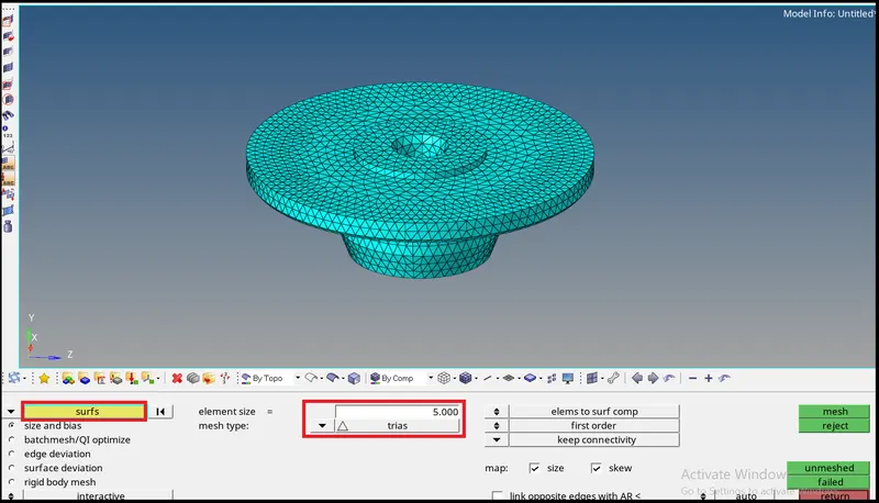
- Suraface being meshed now we will go for tetra mesh.
- Go to 3D > Tetramesh > set parameter > tetramesh.
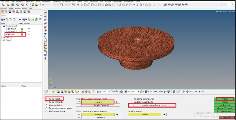
- Check for tet-collaps
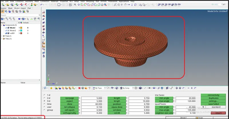
- As we can see there is 0 elemtal failure due to tet-collaps.
For another component we will use quick tetramesh-
- For that first give shell mesh on the surface of component
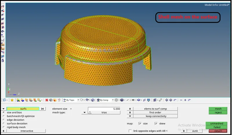
- Now Go to view > browser > hypermesh > utility
- Then go for Geom/mesh.
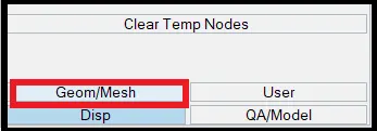
- Then check for quick tetramesh.
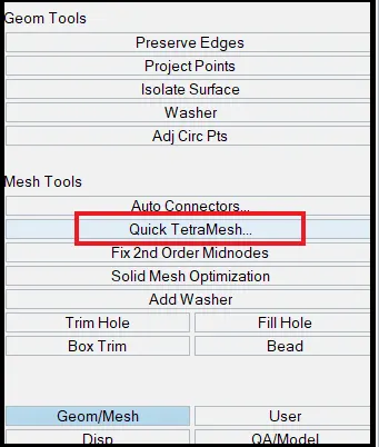
- Now fill all the requirment details for the quick tetramesh panel and hit on mesh button.
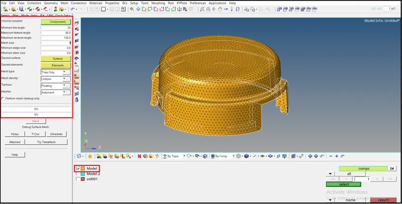
- After selecting component and mesh parameters need to be feeded then hit on mesh button.
- We will got the tetramesh.
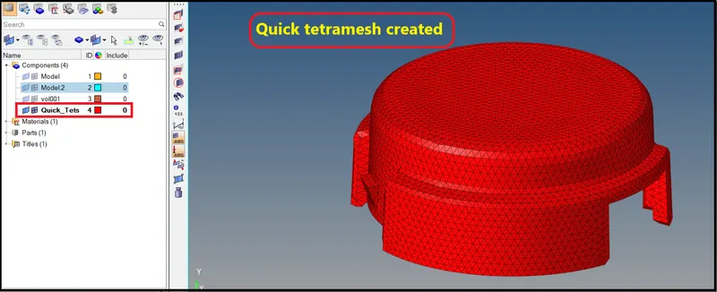
2nd Model- Arm bracket-
Imported model-
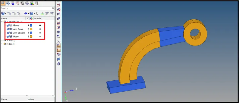
- As we can see there are 4 sub component in this model.
- So now we will go indivisually for each component.
1.Base-
- First create 2D shell emsh on the top surface.
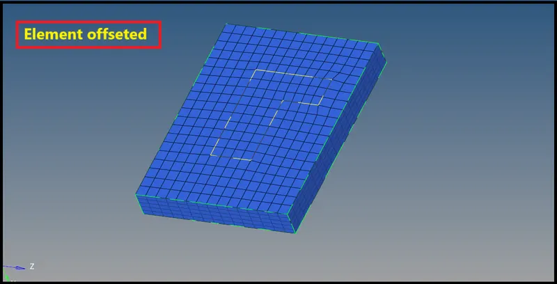
- Then we will convert those 2D shell into 3D by offsetting those 2D shell elements.
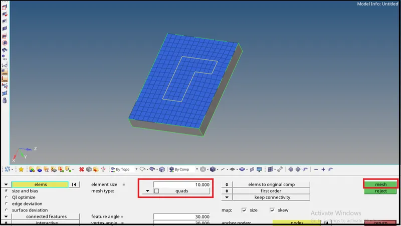
- 2D shell elements of 10 mm size created.
Now, Go to 3D > Element offset > Eelect Element by face > Along geometry surfaces > offset vlues
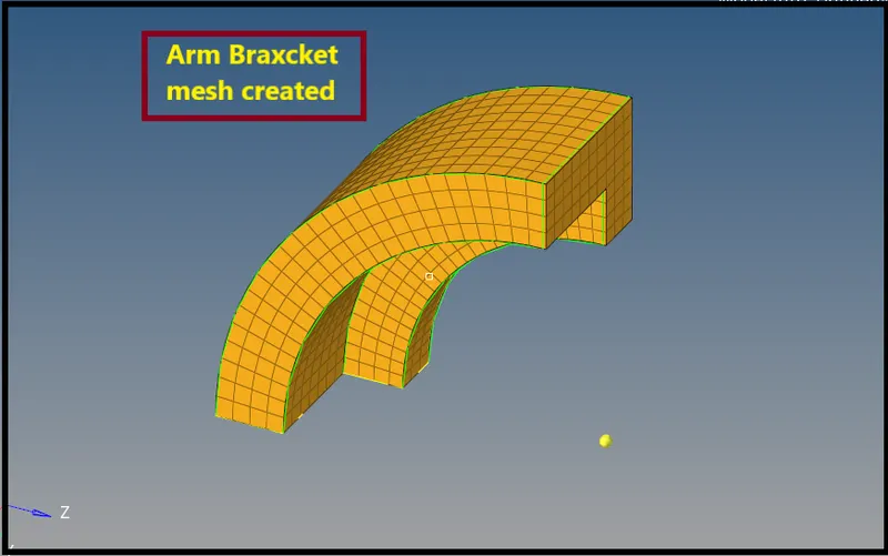
2. Arm curve-
- First mask all the hex element because we will spin the 2D elements in arm curve.
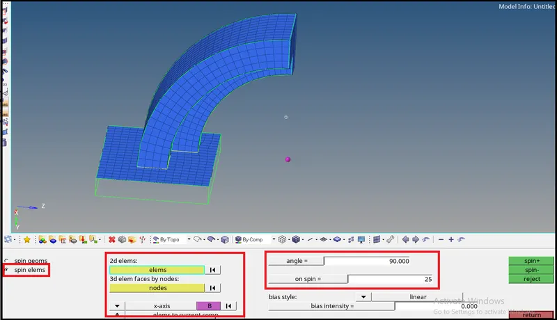
- Will spin the 2D shell elemtns of base component in order to created 3D elememnts for arm curve.
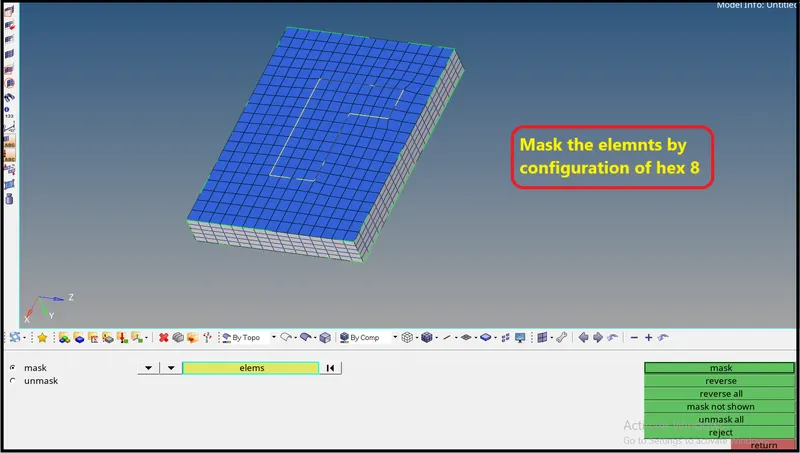
- Now select the base elements which we need to spin through arm curve.
Go to 3D > spin > select elements > slelect the axis of rotation and center point > no. of division
3 Arm staright-
- In arm straight we will use linear solid methode-
- Before that provide 2D mesh on destination surface alsoof same nuber of elements.
- Then create face elements on arm curve by tool > Find faces so that we can use 2D mesh to be use for linear solid.
Go to 3D > Linear solid > select elements > select identical nodes on each mesh
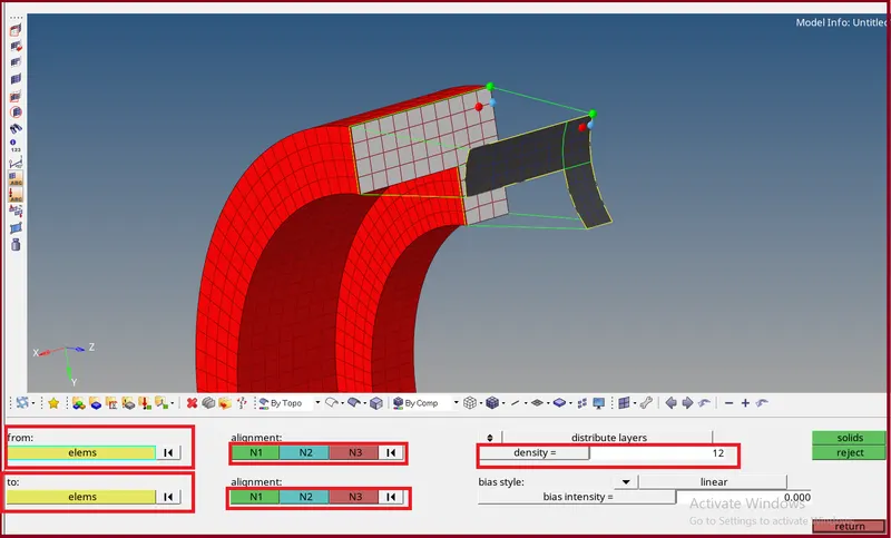
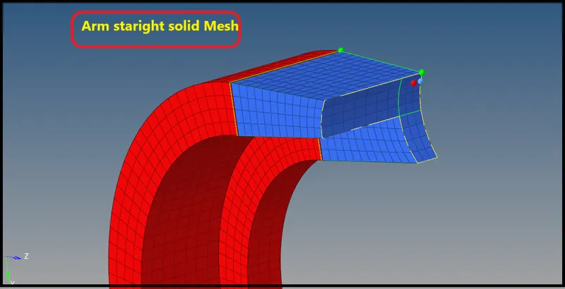
- Now delete faces in order to avoid 2D shell mesh on surface.
4. Bose-
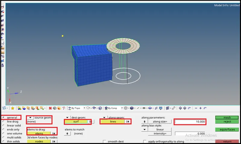
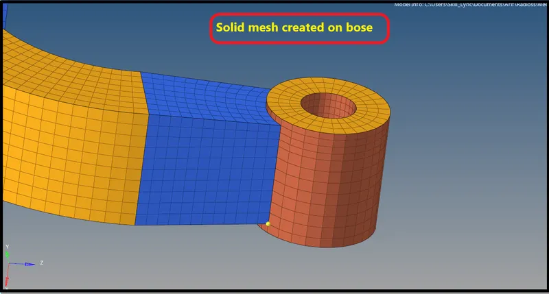
- For bose component we will use solid map, First create 2D shell mesh on one side and map those 2D eleemnts on other side.
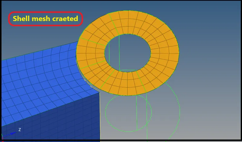
Now Go to 3D > Solid Map >
Result-
- Calcuation for all the value asked in question is done.
- Then Engine File according to the new value is edited.
- Checked for all animation file which created.
- Then performed 3D mesh on housing and Arm bracket component.