Week 1 Spur Gear Challenge
Aim-
- To do deck setup for spur gear and run the simulation to analyze the results with different materials.
Objective-
- Go for structural analysis in ansys workbench and click on engineering data to select material.
- To sleect material from engineering data source,for this challenge select Cast Iron(ductile) and create Cast steel,Bronze cast material.
- Then import the spur gear geometry and open it in spaceclaim and fix the issue if any and close the space claim.
- Update the model by right click and and open the ansys mechanical by clicking on edit once right click on model.
- Now perform deck-setup here, give all connections,boundary condition,loads and output request for simulation.
- Then solve the model and compare the results with different cases and draw graphs for that.
Spure gears and its Applications-
Spur gears are a type of cylindrical gear, with shafts that are parallel and coplanar, and teeth that are straight and oriented parallel to the shafts. They’re arguably the simplest and most common type of gear – easy to manufacture and suitable for a wide range of applications.
The teeth of a spur gear have an involute profile and mesh one tooth at a time. The involute form means that spur gears only produce radial forces (no axial forces), but the method of tooth meshing causes high stress on the gear teeth and high noise production. Because of this, spur gears are typically used for lower speed applications, although they can be used at almost any speed.
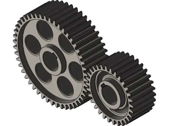
Materials use- Spur gears can be made from metals such as steel or brass, or from plastics such as nylon or polycarbonate. Gears made of plastic produce less noise, but at the expense of strength and loading capability.
Unlike other gear types, spur gears don’t experience high losses due to slippage, so they generally have high transmission efficiency. Multiple spur gears can be used in series (referred to as a gear train) to achieve large reduction ratios.
- Transmissions.
- Conveyor systems.
- Speed reducers.
- Engines and mechanical transportation systems.
- Gear pumps and motors.
- Machining tools.
Stress Intensity-
- The stress intensity factor is the magnitude of the stress singularity at the tip of a mathematically sharp crack in a linear elastic material.
What it means in Ansys:
- The stress intensity factor is a concept in Fracture Mechanics that is used to measure the stress concentration at a crack tip. In safety design, It is compared to a critical value and evaluate whether a component or structure is prone to fracture.
Procedure-
Step-1:
Open ansys workbench and set the case of structural analysis on workbench UI.
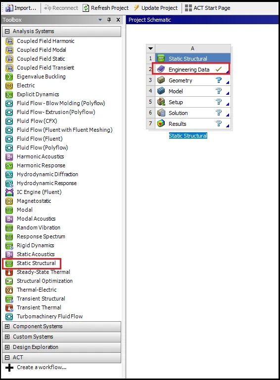
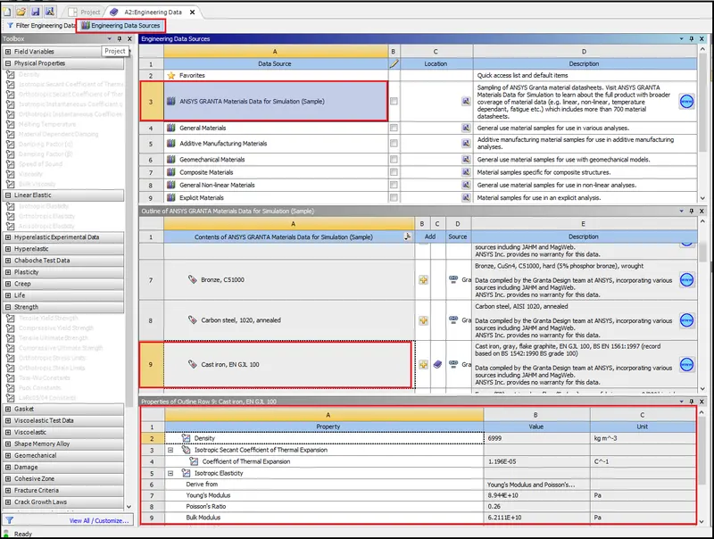
- Now click on engineering data and it will open material window from there select ANSYS GRANTA materials and choose cast iron predefined material quality.
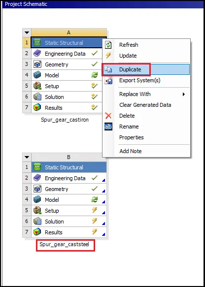
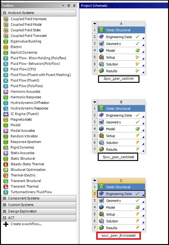
For second material create a second case by duplicating first case the from engineering data change the material.
Duplicate for case-2
- Click on Engineering data in second case and then a new window will pop-up now from the engineering data sources we can select any predefined material or we can create a seperate material.
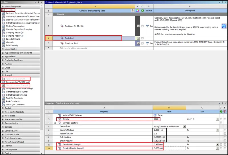
- For that click on "click gere to add a new material" and rename as cast steel and set all quality for that material as given for the challenge.
- Simmilarly create 3rd case.
Case-3
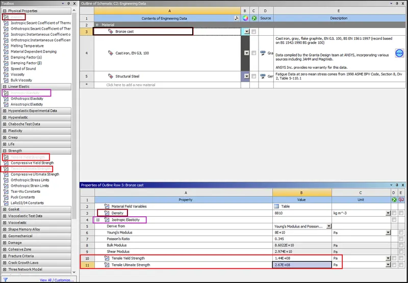
- Set all material quality as given for this challenge.
Step-2: Import cad file in Geometry and open it in space claim.To check weather cad model is fine or not,if any error will found then fix it.
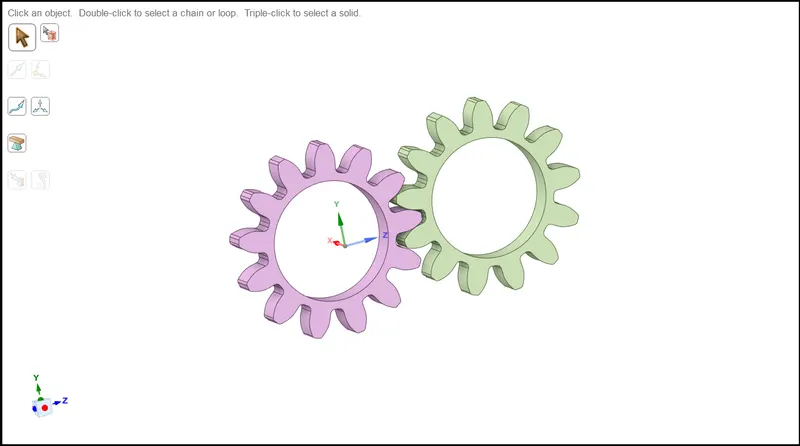
- Here cad model is looks fine so now will move on next step.
Step-3 Update model and open in ANSYS mechanical
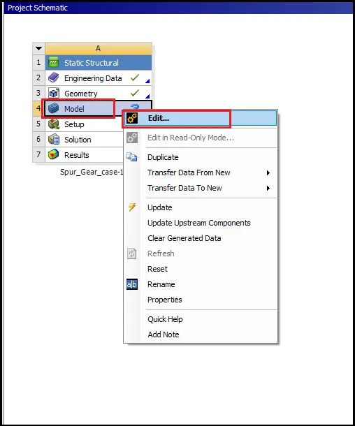
- After clicking on edit model will open in ansys mechanical.
Now after opening it in ansys mechanical check the geometry details and assign material from there as required.
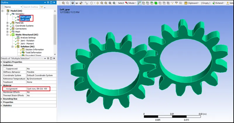
Now check for proper connection-
Contacts- In contact connection since this case gear tooth faces will come into contact so select faces for both gear simulteneously as contact and target.
Default contact already shown by ansys-
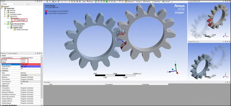
Now Select all faces which will get into contact during simulation.
Contact- Material with low stiffness (total 26 faces selected)
Target- Material with higher stiffness (total 26 faces selected)
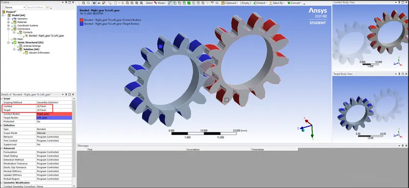
- Now define the contact behaviour and all other definitions.
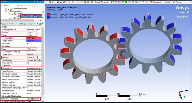
Frictional Contact-
- Frictional contact allow frictional sliding over the surface with no seperation.Since we give positive frictional coefficient value.
- So the contact will be handle shear stress upto a limit depending upon frictional value given after that it will slide.
Augmented Lagrange-
- Using agumented lagrange it enables the contact to come out as soon as it gets into contact and avoid unnecessary chattering to reduce vibration and noise.
- It improves the stiffness of component in order to avoid penetration and chattering of meeting contacts.
Interface treatment-Adjust to touch:
- After enabling it, gaps or any kind of initilal penetration will be removed and as name suggest it follow a simple contact between surface which are going to be in conatct during simulation.
- If gaps are there then the parts might start flying during simulation,but in case pf concentric cylinder a manual offset value should be provided by user.
Step-4:Joint connection-
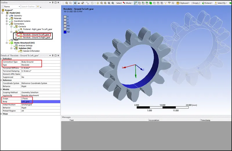
- In contact itself will define the revolute joint connection in which we will give revolute joint connection to each gear w.r.t. to ground.Because the gear is going to rotate on an axis so that here provide revolute joint for each gear w.r.t. ground.
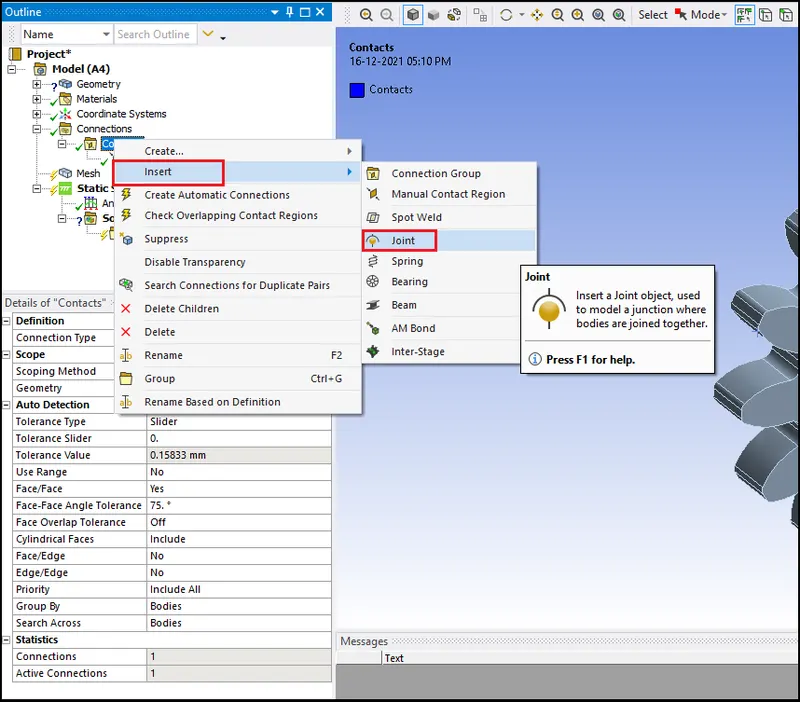
- Now select connection type as Body to ground and type as Revolute inner radius face of gear.
- Simillary go for 2nd gear as well and create revolute join connection.
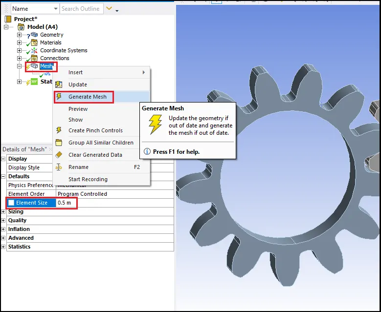
Step-4: Mesh Generation
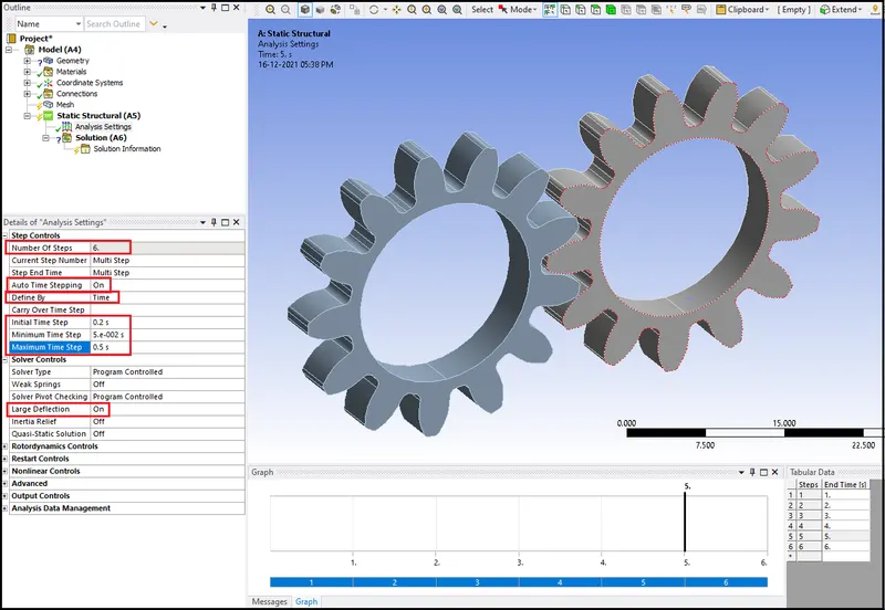
Step-6: Analysis setting-
- Since we are intrested in looking all stress, strain, contact force, deformation results for one complete revolution.
- So for analysis devide it into 6 step instead of one step to see the results properly in each step.
- Now select all steps togather and define analysis setting, Keep auto time stepping to be on define it by time and give tim-step values.
- Select large deflection to be on to evaluate results for any large deflection in simulation if found.
Step-7:Apply joint load
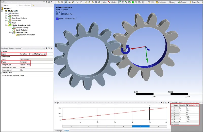
- To give joint load right click on static structural and select joint load.
- Select type as rotation
- Give Rotational joint load for right gear (Revolute-Ground to Right gear),
- Give 30 degree rotation in each step in tabular data so total will be 180 degree.
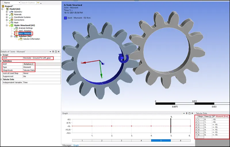
- Simillarly give moment load on left gear (Revolute-Ground to Right gear).
- Give 10 N-m moment in each step.
- Negative value to make it clockwise, cause right gear joint load is given in anti-clockwise direction so to give proper roation both gear should move in opposite direction.
Step-8: Request for output results
- For this simulation we will request output results for Total deformation, von-mises stress and equivalent strain.
- For that right click on solution and select all three option seperately.
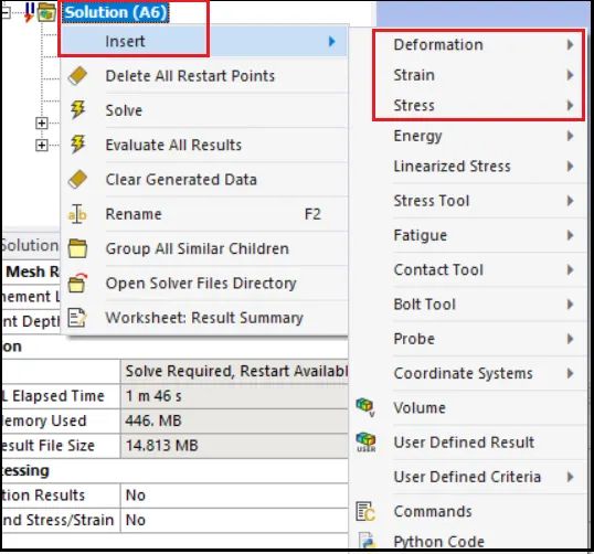
- Now as mention in the challenge we want result for stress intensity also,
- So now right click inser>stress>intensity.
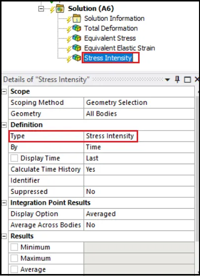
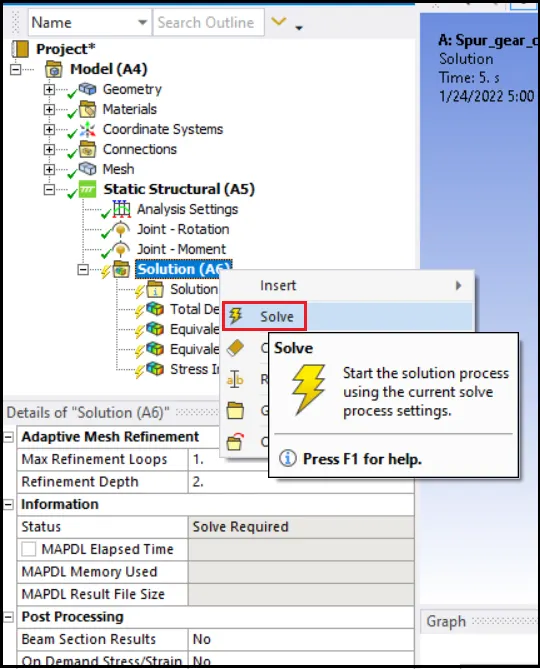
Now Hit on solve,
Right click on solution > Solve
Result Evaluation-
Von mises stress-
case-1
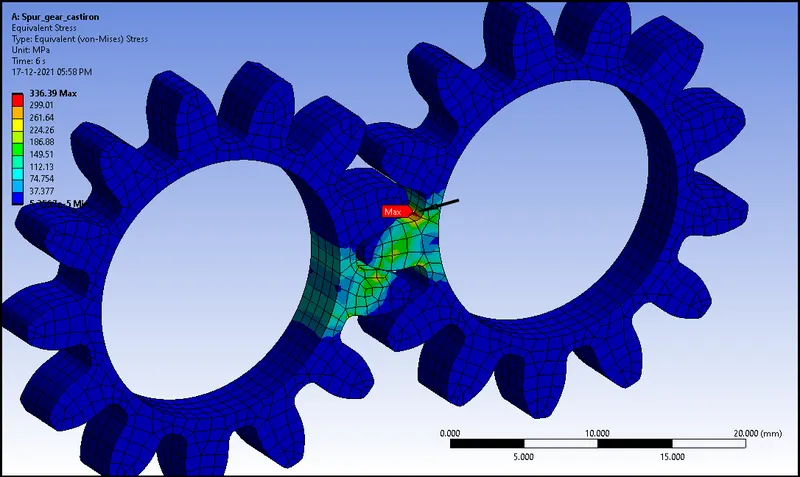
Here maximum working stress we can see from above image is 336.39 Mpa
and check Ultimate tensile strength for cast Iron material in ansys workbench In Engineering data-
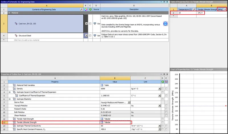
Now Factor of safety =Ultimate tensile strength/Working stress
= 141.4/336.39
FOS(cast iron)=0.4203
Since FOS is less than 1 its mens material will fail.
Case-2
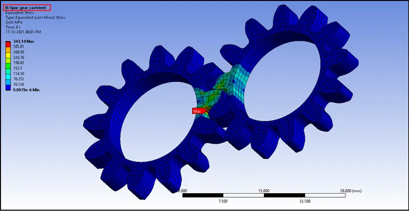
Here maximum working stress we can see from above image is 343.14Mpa
and check Ultimate tensile strength for cast steel material in ansys workbench In Engineering data-
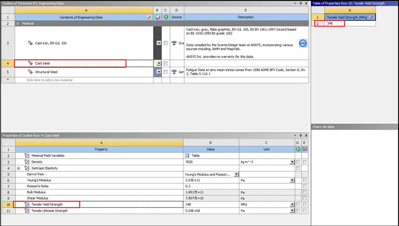
- Lets calculate factor of safety w.r.t yielding,
Factor of safety=Yield tensile strength/Working stress
=343/343.14 =0.9995 Less than 1 so material will perfoerm yielding means it can go under plastic deformtion,
Now check for ultimate strength,
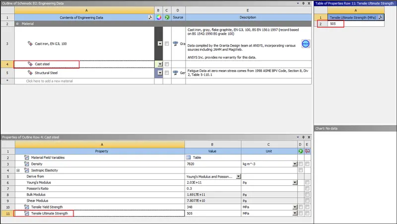
FOS(Ultimate)=Ultimate tensile strength/Working stress
=505/343.14 = 1.4717 Greater than 1 means material will not fail and this value is acceptable.
(Note:UTS value from below picture)
Case-3
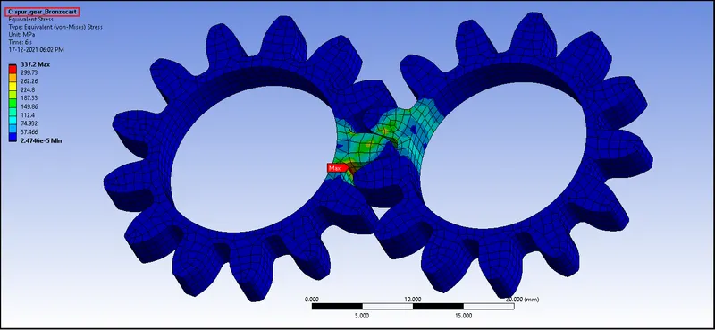
Here maximum working stress we can see from above image is 337.2Mpa
and check Ultimate tensile strength for Bronze cast material in ansys workbench In Engineering data-
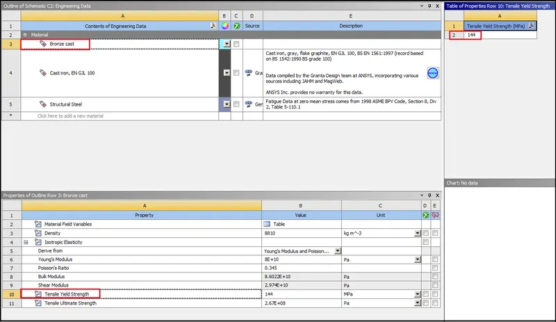
- Lets calculate factor of safety w.r.t yielding,
Factor of safety=Yield tensile strength/Working stress
=144/337.2 =0.4270 Less than 1 so material will perfoerm yielding means it can go under plastic deformtion,
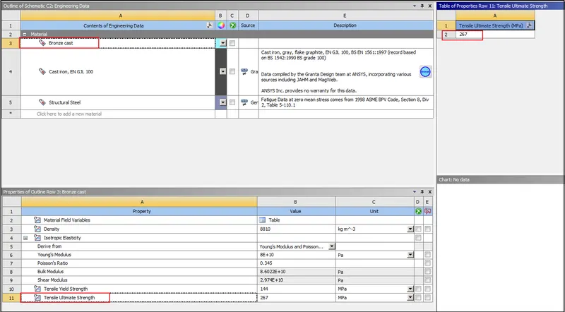
Now check for ultimate strength,
FOS(Ultimate)=Ultimate tensile strength/Working stress
=267/337.2 = 0.7918 less than 1 means material will fail.
(Note:UTS value from below picture)
Result-
- From above analysis we can say in tems of fracture failure case-2 (Cast steel) Material will be preffered.
- And in terms of strength (least value of Induced maximum stress) is in cast iron which is 336.39, least from all three cases.
Stress Intensity-
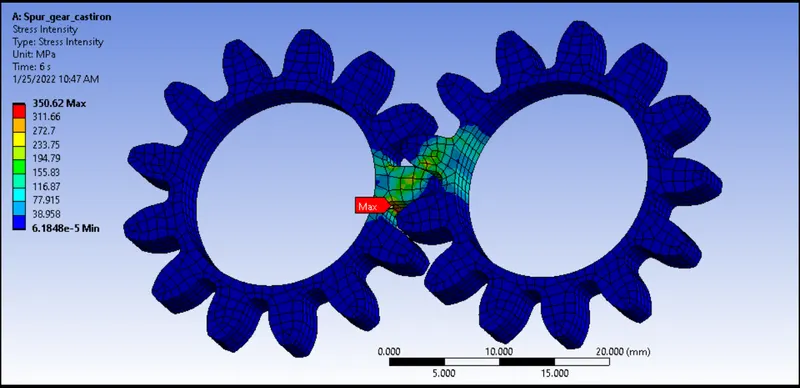
Case-1
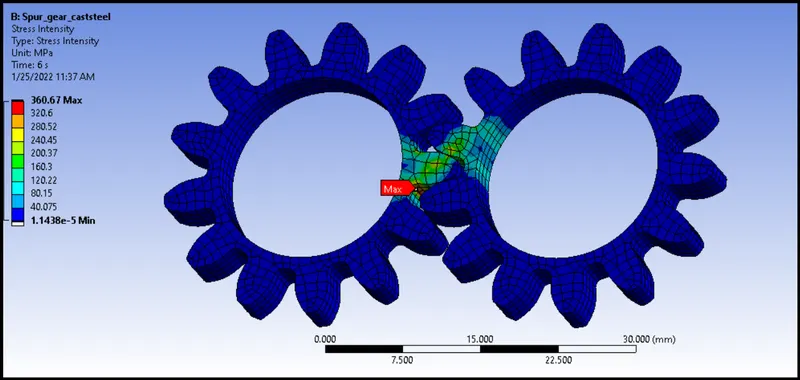
Case-2
Case-3
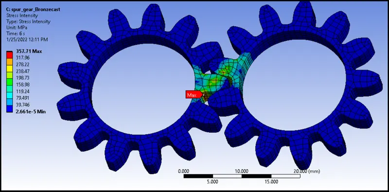
Result-
- From above simulation we can see least value of maximum stress is noticed in 1st case (cast iron).
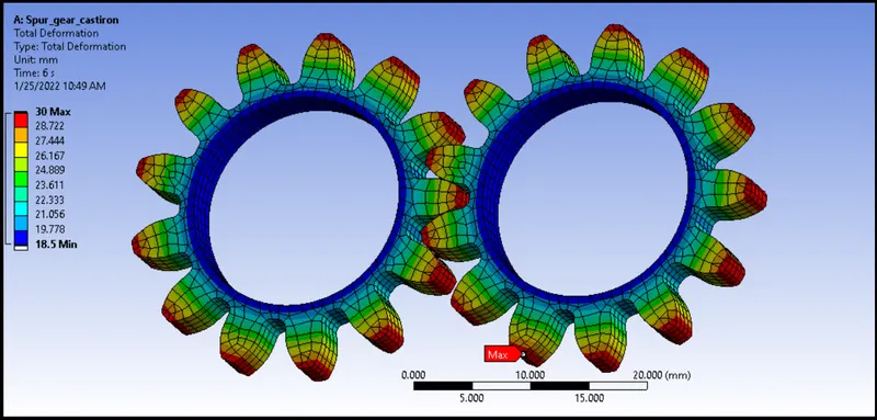
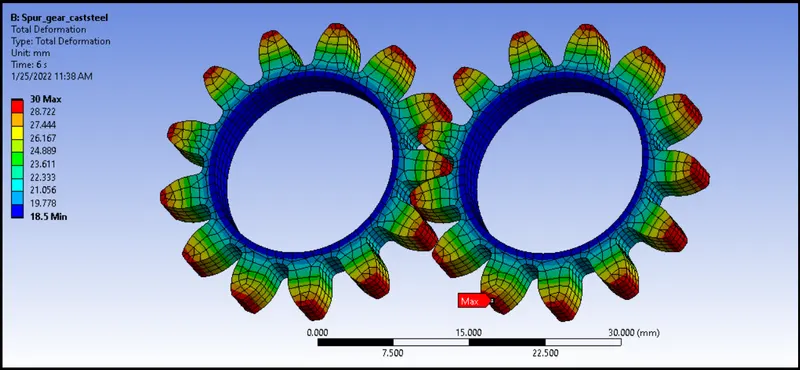
Total Deformation-
Case-1
Case-2
Case-3
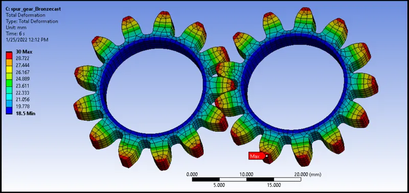
Result-Maximum and minimum deformation results are same in every case.
Result comparision-
| Cases | Total Deformation(max) | Total Deformation(min) | Equivalent stress (Max) | Equivalent stress (Min) | Stress Intensity(max) | Stress Intensity(min) |
| Case-1 (Cast iron) | 28.722mm | 18.5mm | 336.39 Mpa | 5.3567e-5 Mpa | 250.62 Mpa | 6.18e-5 Mpa |
| Case-1 (Cast steel) | 28.722mm | 18.5mm | 343.14 Mpa | 9.9079e-6 Mpa | 260.67 Mpa | 1.143e-5 Mpa |
| Case-2 (Bronze cast) | 28.722mm | 18.5mm | 337.2 Mpa | 2.4746e-5 Mpa | 357.71Mpa | 2.661e-5 Mpa |
Conclusion-
- CAD model imported in ansys workbench and edited in space-claim.
- Created material card for three different cases.
- Model opened in ansys mechanical and performed deck set-up, boundary condition-assign contact and joint connections.
- Then meshed the model with 1mm element size.
- Defined analysis setting in 6 steps and define value for time steps.
- Then applied load conditions ie joint load (rotation and momements) for mating gears.
- Requested for output results and then run the simulation.
- Result evaluated for all cases and compared in every aspect of applications.