Week 6 - Creating connection for Rear door
Aim-
To deploy appropriate 1D connectors to the Rear Door model using ANSA.
Objective-
- To creat seperate PID's for indivisual parts of this car door.
- Creating different PID's will help in identifying the indivisual parts during deploying connections.
- Creating RBE2 1D elements for bolt joints.
- Creating RBE2 on door handle and then applying mass on center.
- Creating RBE3-HEXA RBE-3 element for the spot weld joint.
- Creating RBE-3 CBUSH RBE-3 elements for weather strips.
Connector's Theory-
• Geometric entities that define connections between other entities
- Used for welding, bolts, adhesives, etc.
- Link geometry or FE entities
- Can be “realized” into FE representations of welds, etc. for any supported solver
- rigids, CWELDs, MAT100s, ACMs, etc
- Connectors allow for easy and rapid:
Creation of FE welds, bolts, adhesives, etc
interactively or from:
• XML file
• MCF (master connectors file)
• Spot welds only
• Switching between different FE configurations of
welds, bolts, adhesives, etc.
Types of Connectors-
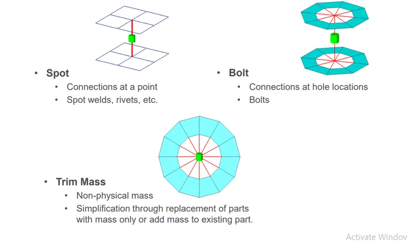
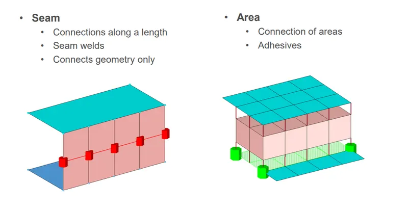
Link Entities - The entities that are being connected
• User can explicitly define link entities or specify a search tolerance
• Can be components, elements, surfaces, nodes, or tags
• Typically components are linked
Connector Location - Where the entities are linked
• Nodes – created at the node location
• Points – created at the point location
• Lines – created for the line
• line may be split into multiple projection locations as specified by the offset,
spacing, and density values
• Elements – created at the element location (adhesives only)
• Surface – created at the surface location (adhesives only)
Connector Realization – The creation of the finite element representation of that connector.
• Rigids, springs, etc., or custom configurations such as ACMs, CWELDS,
Types of connector state-
Connector State – Whether an FE representation of a connector has been created.
• Unrealized - The initial status of the connector entity upon creation.
• Realized - The status only if creation of the FE weld representation at the
connector was successful.
• Failed – The status if the creating the FE weld representation at the connector
was not successful.
Procedure:
Stage-1
Importing the Model:
- Here we will ne importing the CAD file into ANSA.
- Here is many types of file format supported by ANSA for CAD model like IGES,STEP and somtimes Parasolid also depending upon the requirment of industries.
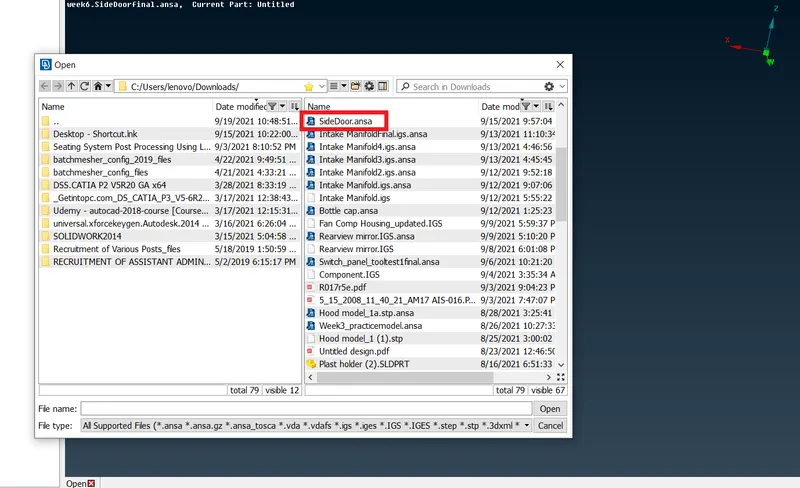
For importing the model
we will go on pull down tab >> File >> open >> select the all format >> select the model from folder
Imported Model-
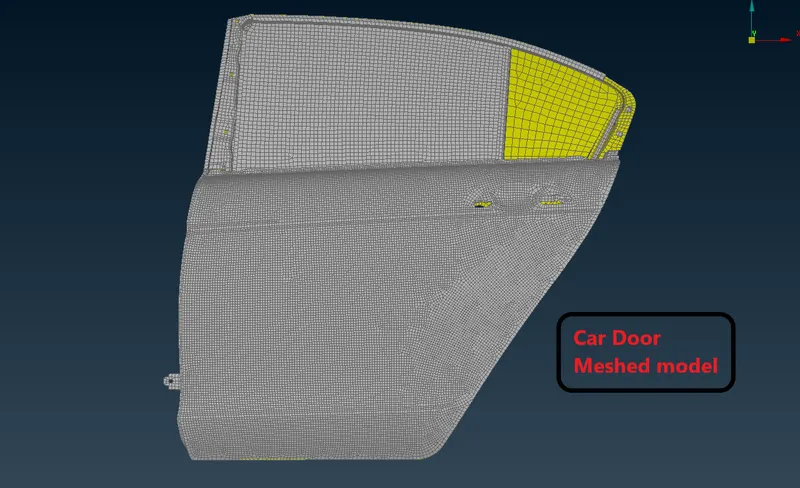
- Now as we can see this is a FEA model so there is no need of performing meshing on the component.
- So we will directly diploye the connection as required place.
Bolt Connection-
- We will start from bolt connection in hinge areas.
- For that we will set new PID's for hinges first so that make indivisual surface selection during providing connection.
For creating property ID Go to Topo module > set PID > select faces > middle click > new window open > right click > New > PShell
Now after creating different PID's for hinges now will go for creating RBE2 Bolt connection.
Deploying Bolt connector-
- First creat a 3D point on COG in points in topo module.
- Select the edges of the hole and then middle click a 3D point will automatically generated.
- Go to Topo module > points > on COG > Edges.
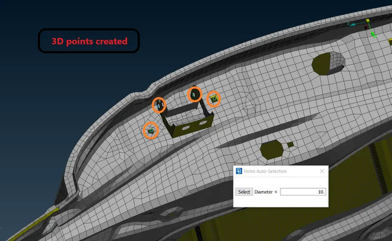
- Now after creating 3D points we will convert it into bolt.
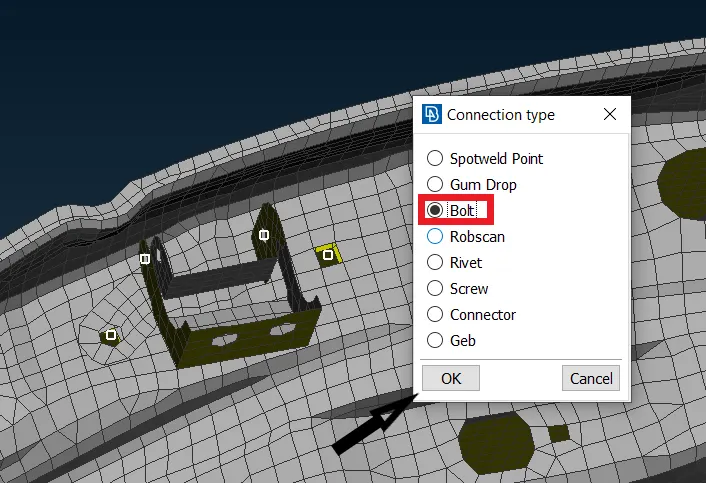
- Go to utilities > convert > 3D points > Bolt > select the points > middle click.
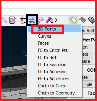 --->
---> 
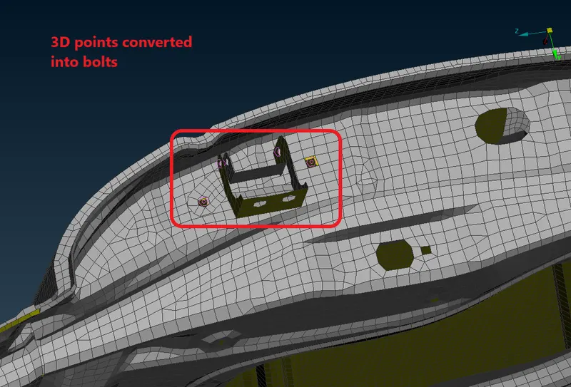
Now To deploy the connection-
Go to the Connection manager > select bolt > Middle click > New window will popup
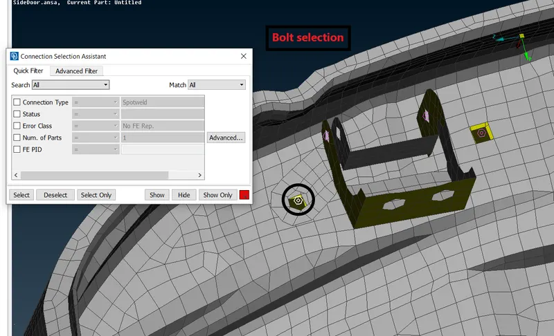
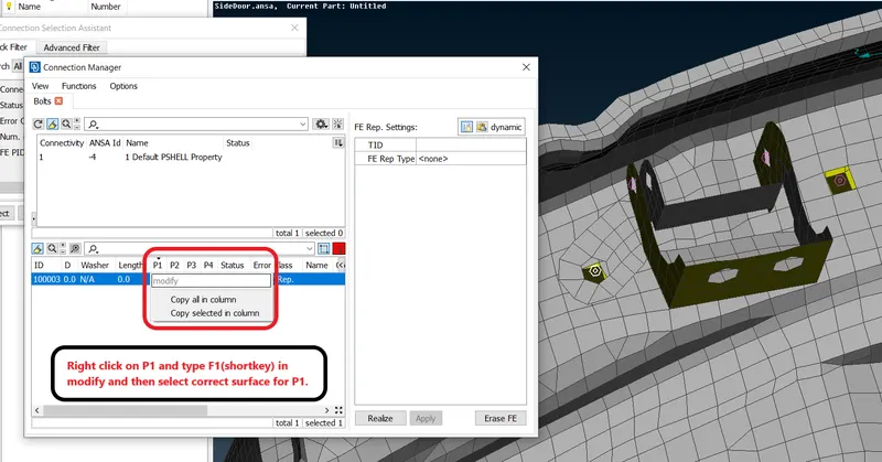
- Now choose the type of connection we need to select Bolt on the option right side (FE Rep type).
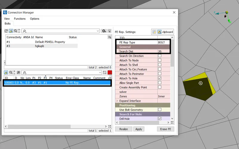
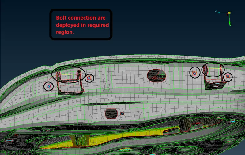
Now apply and realize the bolt connection-
- And in between two bolt we will deploy 2 node RBE2.
Creating RBE2 Element-
- RBE2 Element- The RBAR and RBE2 element can be used for connecting two nodes to modela rigid weld with all 6 DOF OR pinned connection with 3 translational DOF's
- The RBDE2 element can also be deploy between more than 2 nodes also to model a wagon wheel type connection between independent and dependent nodes.
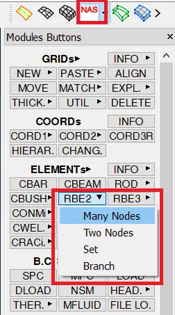
To create this RBE2 connection go to NASTRAN deck,
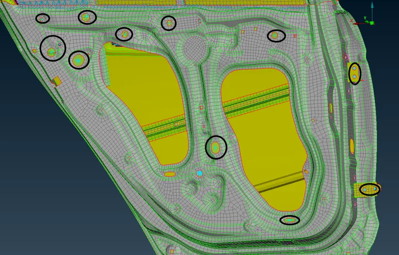
Creating RBE2 cluster elements-
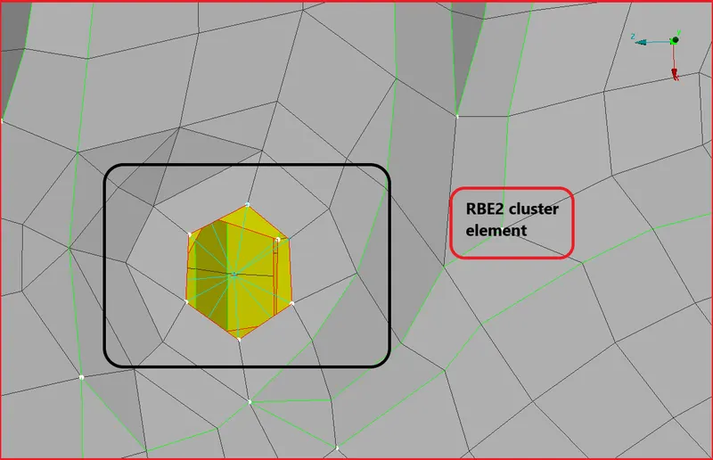
- To creat the RBE2 cluster element Go to NASTRAN deck > elements > Many nodes.
- Now select the all slave nodes(dependent) of both plate(can be more than two plates) which we need to be connected then click middle mouse button continuously till the connection deployed.
- The master node(independent) autometically will created after clicking middle mouse button.
Connection on Rail with Glass-
- Here also we will use cluster RBE2 elements.
- Before that we need to modify some geometrical reprensentation of elements of rail.
- We need to extend it till parallel position of glass.
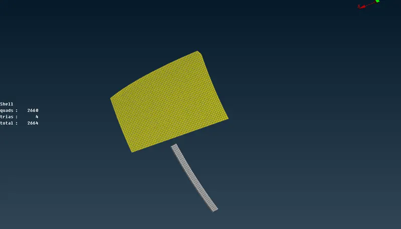
- To extend the rail Go to the mesh module > Grid > MVfree > select node >Right click to give coordinate system > midddle click and extend
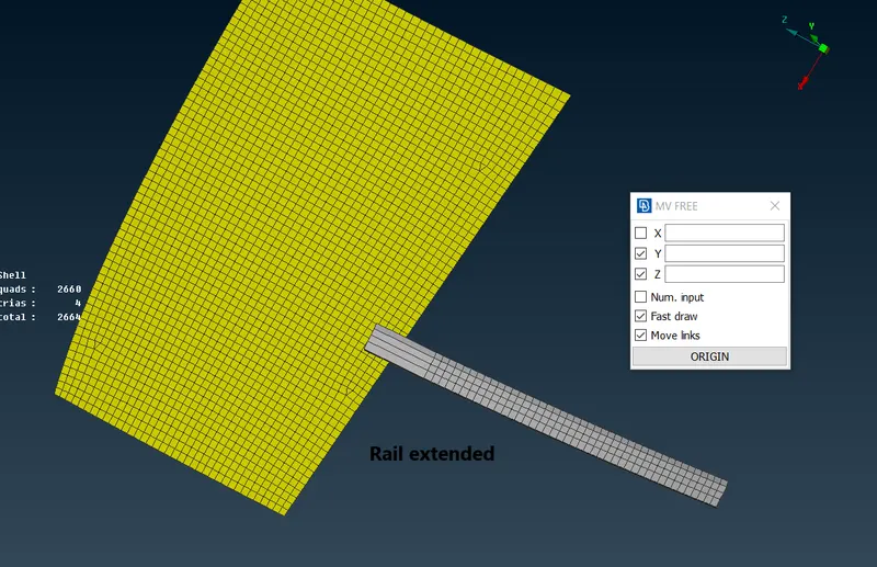
[Note: Reconstruct the mesh here ]
- Now deploy RBE2 Cluster connection same as we did previously.
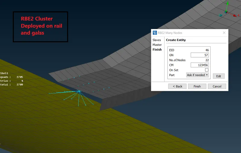
Creating connection for door handle and applying mass-
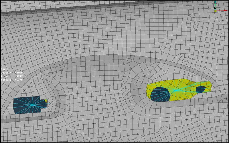
- For door handles we have to represnet it as a concentrated mass, this is thw way to model a door handle in FEA.
- For applying mass first we need to creat RBE2 rigid connection with multiple slave node on both side of handle.\
- And then creat connection between those two RBE2 for that gain go for RBE2 > Multi node and select both master node of indivisual RBE's.
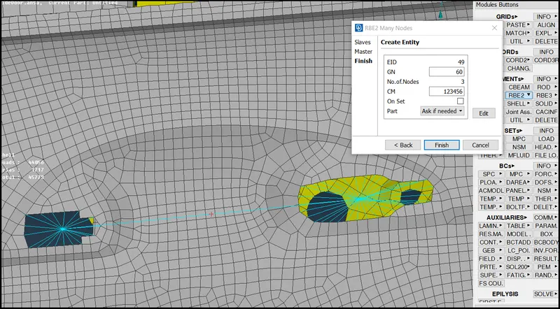
- Now we will apply a mass in between by using CONM1 commant in NAST deck.
- Go to NASTRAN Deck module CONMi > CONM2 > select master node > middle click
- Now a new windo will popup, here we have to fill aal details.
- Here will assume a mass of 100 grams which will be putn in the form of tonnes.
- So 100 grams= .0001 tonn
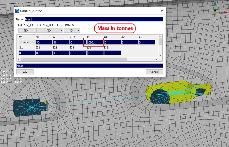
- Mass is applied now-
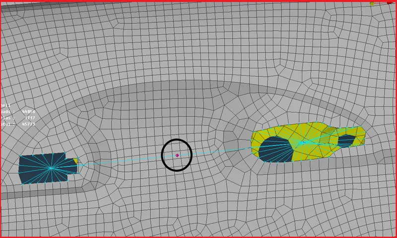
Deploying CBUSH connection-
- Basically CBUSH connection will deploy for weather strips which helps in isolating the gate mirror from outside.
- So here we cant deploy rigid connection because weather strips are rubber material.
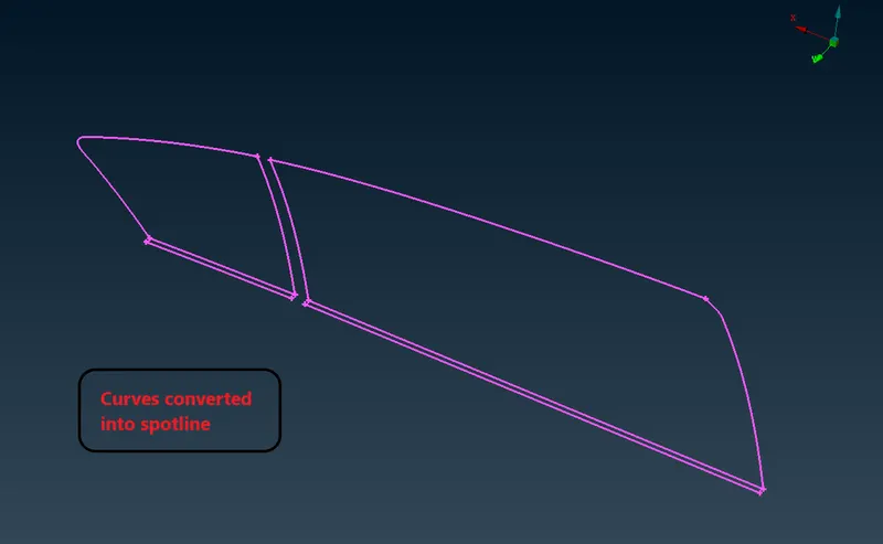
- So first we need to extract a curve from that region on which we have to deploy CBUSH.
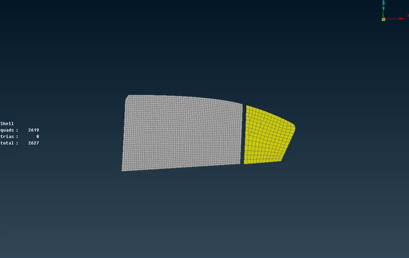
- To extract a curve from their boundaries,
Go to mesh module > perimeter > Feature2curve > select the element edges > middle click
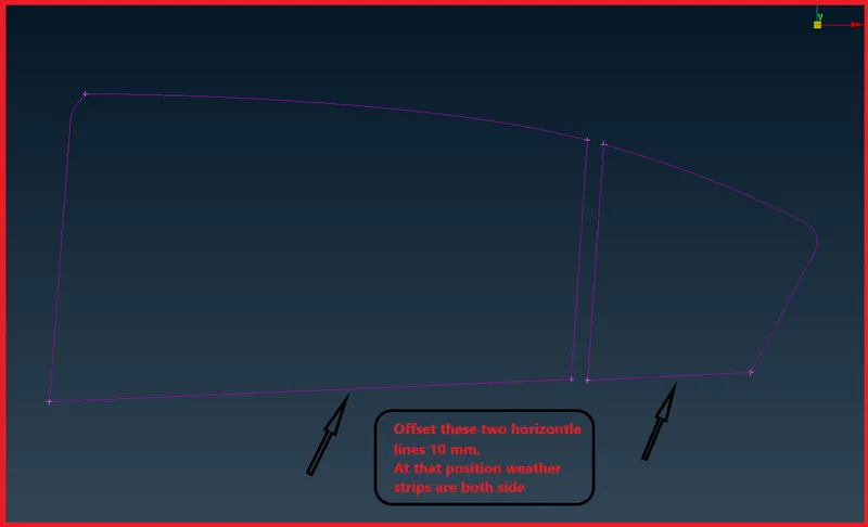
- Now convert this curve to spot line.
- Now go to connection manager from utilities panel.
- And make a CBUSH connection, simmilar selection of parts just we need to change the type of connection and its features.
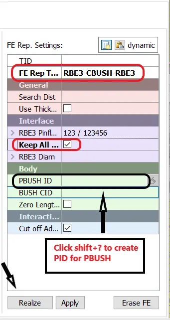
- In PBUSH ID enter all the different K values as per given project.
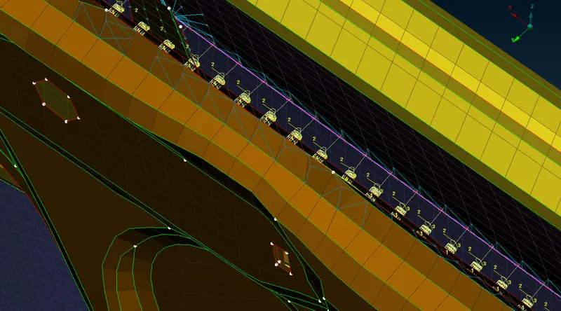
- Simmilarly we will do for other regions also,
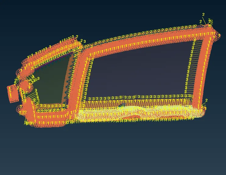
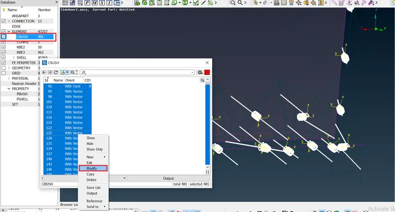
- Since we know that all the CBUSH are having thier own local orientation which are different.
- So here we will change the orientation of the connections according to global orienation.
- For that select all the CBUSH connection and modify it,
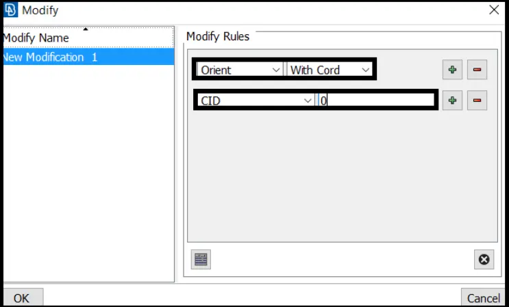
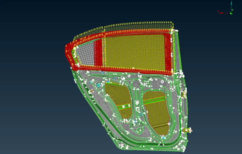
- Now we will see the new orientaion of the CBUSH.
Deploying spotweld connecton-
- To creat spot weld, first we will creat a 3D point.
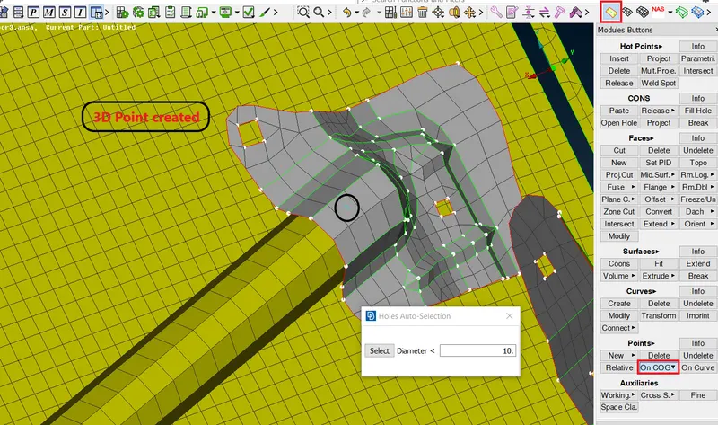
- Now convert this 3D point into spot weld in utilities > convert > select point.
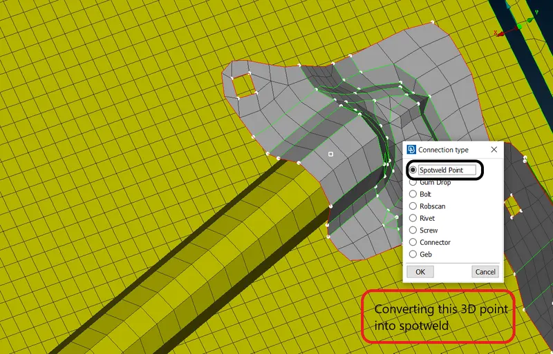
- Now open the connection manger and select the spot weld.
- Then select the appropriate part which we nedd to connect by spot weld.
- Also put the appropriate distance, In FE representaion type is RBE3-Hexa RBE-3.
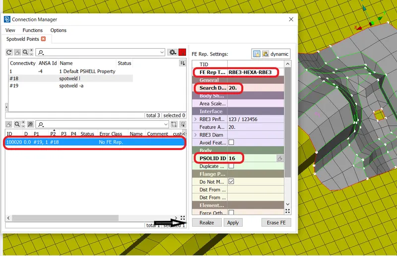
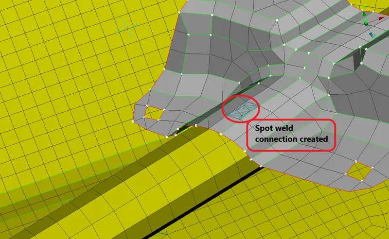
- Now apply and realize the connection to deploy it.
Final model with all appropriate connection's-
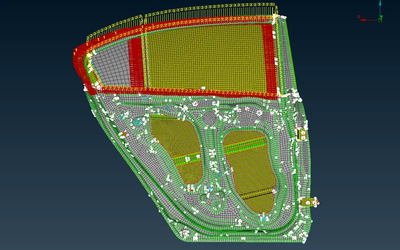
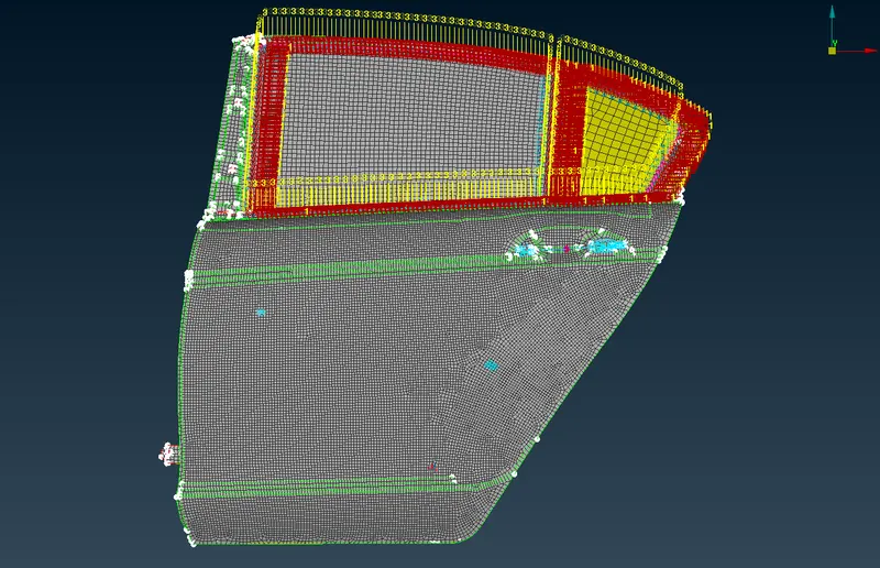
Result-
- All the connectors deployed succesfully with all types,
- Bolt
- RBE2 Rigid
- RBE2 Cluster
- RBE3-CBUSH-RBE3
- RBE3-HEXA-RBE3
- CMass (CONM2)
- Spot weld
- All these connection are deployed and realized successfully without any error.
Learning outcome-
- How to make seperate PID specially for connection types.
- How to make realized the connector successfully.
- How to debug a connector if it is failing from realization.