Week 12:Project-1-Meshing of Door Inner Panel Challenge
Project- Meshing of car side Door inner panel.
Aim- Performing preprocessing on the given side door inner panel(plastic body) using hypermesh as preprocessing software in this project.
Objective:
- To clean the parent body also for better midsurface extraction.
- Then to extract the midsurface from parent body.
- To perform cleanup on midsurface also.
- Mesh the midsurface with given quality criteria with better mesh flow.
- Creat different collectors to organize the elements to different collectors to assign the required thicknes.
Given CAD model:
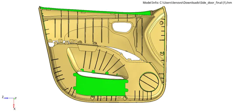
Figure1:By components

Figure2 : component 1
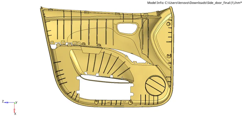
Figure3: component 2
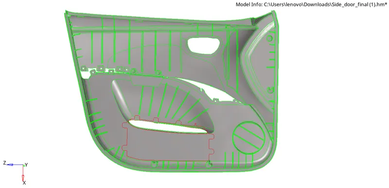
Figure4 : Components in Topo mode
Usually we perform geometry cleanups on topo mode because in topo mode all the geometrical details shows clearly like feature lines, free edges, Ribs, surfac fillets, edge fillets etc.
Theoretical Aspect:
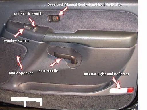
Car door interior:
- The interior side of the door contains switches as well as the internal mechanisms that control the windows, etc.
- If the car has power accessories, the doors will have switches for the windows, locks and (on the driver’s side) the power mirrors.
Door Panel:
The door oanel covers internal parts like the window regulator, the power window motor, and the wiring. In older cars, door panels used to be made out of cardboard and upholstered with material that matches the rest of the upholstery within the cabin. On the other hand, most modern cars have door panels made from plastic.
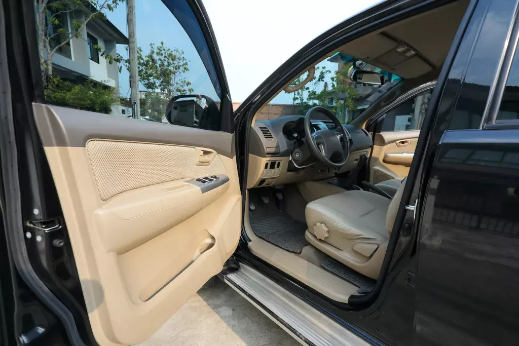
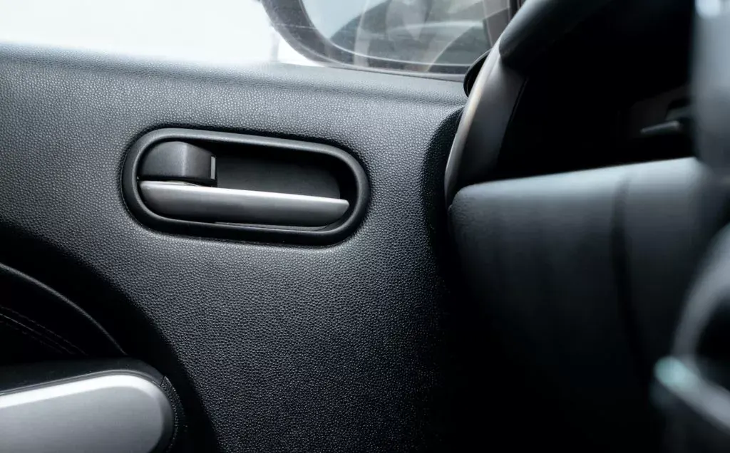
Interior Door Handle
- The interior door handle disengages the door latch so you can push the door open. Most modern interior door handles are made from plastic.
- The linkage for both the interior and exterior door handles is found inside the door, underneath the door panel.

Window Regulator
The car window regulator is a scissor-like mechanism that allows the window to be moved up and down. Depending on whether the car has power windows or manual windows, the regulator is either operated by a crank or an electric motor.
- If this part fails, your power windows can become stuck and will no longer be able to roll up or down.
- As mentioned, manually-controlled windows use a crank to move the window up and down. On the other hand, cars with power windows use an electrical switch to operate the window motor.\
Power Window Motor:
Vehicles with power windows use a small electric motor to move the regulator up and down. Like other window components, the motor can be found behind the door panel.
Door Locks and Latches:
Car doors are equipped with latches and locks to keep the door in place and prevent unauthorized access to the inside of the vehicle. There are manual locks and power door locks.
Power door locks are operated with a switch and, in some cases, they can also be operated via a key fob. Also, most vehicles have a child safety lock feature that prevents backseat occupants from opening the doors.
Materials we use in side dor inner panel:
Door panels are expected to meet one of the toughest sets of requirements among interior car components. These panels should be designed to withstand and channel loads into the body of the car while being thin (<2 mm).
- The inner panel is basically composed of a single piece of molded plastic, or may be of many pieces of plastic.
- As per time when manufacturing evolved instead of using metals we start using cardboards, molded plastic, fiber glass and wood.
Traditionally, the car door is built from steel; an outer panel and an inner panel which also serves as a mounting plate for the various attachments. The application of aluminium has been on the door lightweighting agenda for a long time.
Procedure:
Stage 1- Importing the model:
- Since we are importing the CAD file model in this challenge.
- So there are many type of file like IGES,STEP and parasolid we can use if we are importing a file into any CAD and CAE software.
But here in hypermesh we can use only three kind of file format:
- IGES(Initial Graphics Exchange Specification).
- STEP ( Standard for the Exchange of Product Model Data).
- SolidWorks.
Now these time most of the industries started working parasolid file formate also.
[Note: While importing the file into graphical user interface be sure that whether the file is .step or .iges file. Otherwise we will face difficulty during importing the model.]
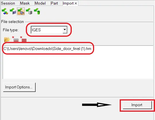
Tool we use to import in the way: File >> Import >> Import Model >> File type >> Open File.(As shown in below picture)
Imported model in GUI :
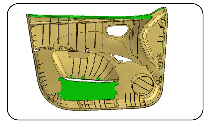
- Now we will check for the solid body after converting it into by topo model.
- After putting the model in by topo mode if model is having solid then it will show in green color.
- For deleting the solid Go to delete panel (F2) > select solid > select by displayed > Delete.
Stage 2- Geometry cleanup :
So after importing the model we will go for check the model for any geometrical glitch lik,
- Unnecessary surfaces.
- Free edges.
- Damaged geometry.
- Unwanted connection between surfaces.
So after checking we will found that there are gemetrical glitch over areas like near to water bottlle space, speaker housing, door locks.
Plastic components:
- As we can see there are pastic rivets in the component.
- Actually due to scanning error in hypermesh it created only single component with plastic rivets.
- So now we will try to arrange it with another new component named as plastic body.
- For that we have to creat a new component for that we will right click on model browser > create > component > and then give a color to it.
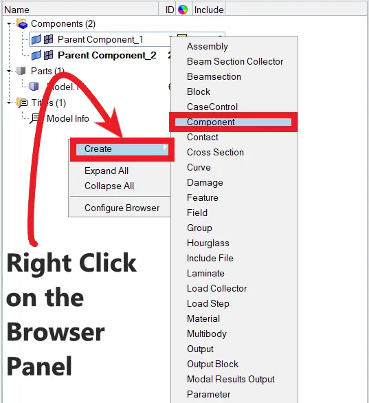
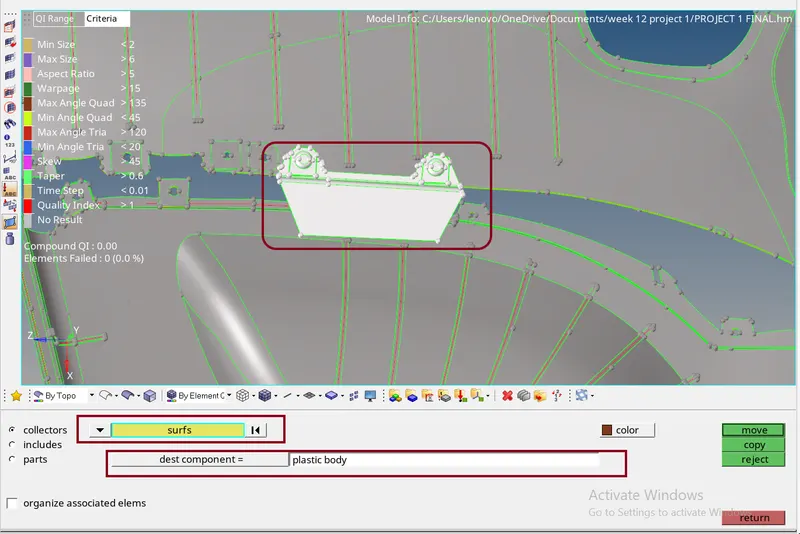
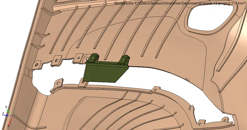
fig: plastic body as component
Stage-3
Midsurface extraction:
- As we can see here auto midsurface extraction is not practical so we will try to extract the midsurface manually.
- For that we have to check for the thickness for the components.
- Click F4 > distance between points > select points > Distance displayed now do half of that (1.4 unit).
- Now we will try offseting the surfaces at mid point.
- For that its good to offset the surface of component named as Parent Component_2 as shown below.
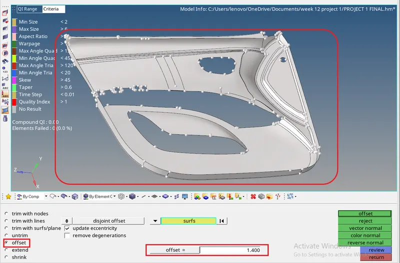
Fig: Offseting parent component_2
Extracting midsurface for Ribs:
- As we can see here ribs on the parent component 1.
- So now we will move on to the component 2 for ribs and try to defeature of surface fillets on it.
How Defeature panel works ??
Go to Geometry panel > Select defeature > select on surface fillet > select the surfaces > put the radius limit as 0.1 to 5 now click on find > shown the surface fillets > now click on remove.
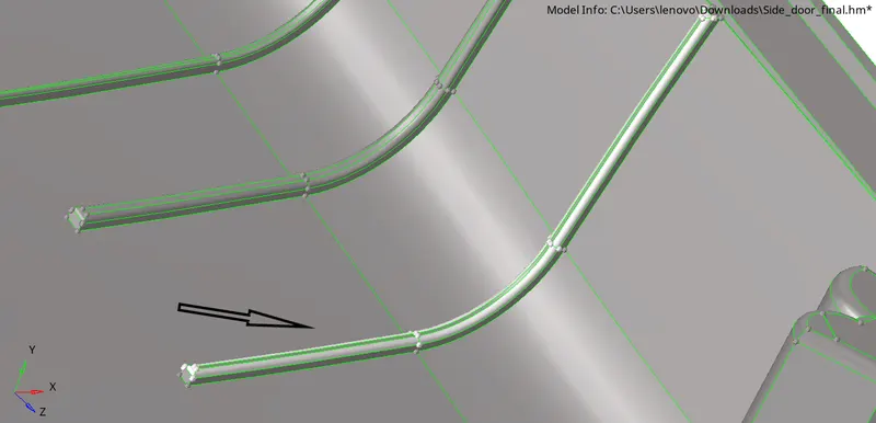

Defeatured fillets :
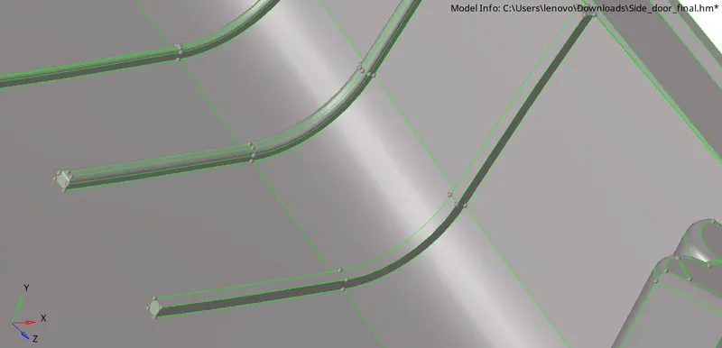 '
'
- simillarly we will do for each fillets and make it fillets free.
After removing the fillets we will cross check for geometrical glitch :
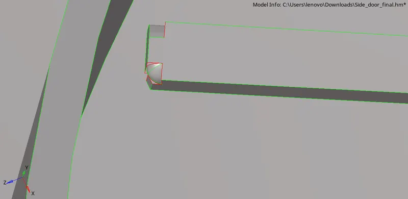
- This glitch can be directly removed by using surface removed panel in feature.
- Means when we defeature the surface after finding the surfaces whithin the limit (0.1- 5 unit) we had a option to remove the surfaces.
- But sometimes after removing the surfaces some portion will still remains so then we will select those surfaces and try to remove it again.
- Otherwise we use line drag options also.
Dragging the lines to form a surface:
Drage along vector:
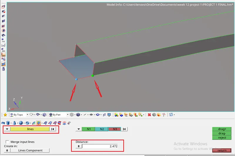
- We will measure the distance between two points and select the lines which we want to extend over in order to extend the rib surface.
- Geometry > surfaces > Drag along vectors > lines > N1,N2,N3 > Distance > Drag
- Then select the node which provide the direction of drag.
- Then click on drag to complete it and see the result.
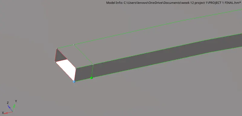
- Now we will make to complete the end surfaces via using rule option in surface panel.
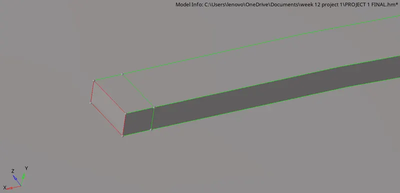
- Now to avoid red line and that unwanted green line we will select the toggle option,and try to toggle those lines.
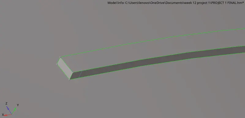
- Simillarly there are many surfaces in this which we need to clear geometrical glitches over there.
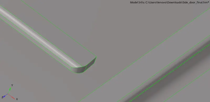
fig: fillets need to be deleted
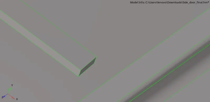
fig: fillet removed
- Another surface glitch.
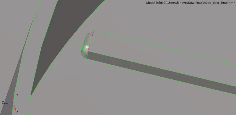
Fig:Try to remove surface fillets.
- Sometimes removing surface fillets also not worked so at that moment we will use those three options.
- Drag line via vector.
- Drag via line list.
- Extend ove edges.
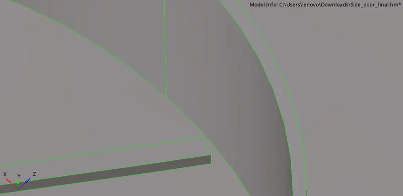
fig: Fillet removed.
Creating holes for this particular surface area :
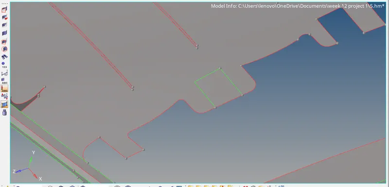
- For this surface we need to put a node first in between and then we will project it on extracted midsurface of parent component02.
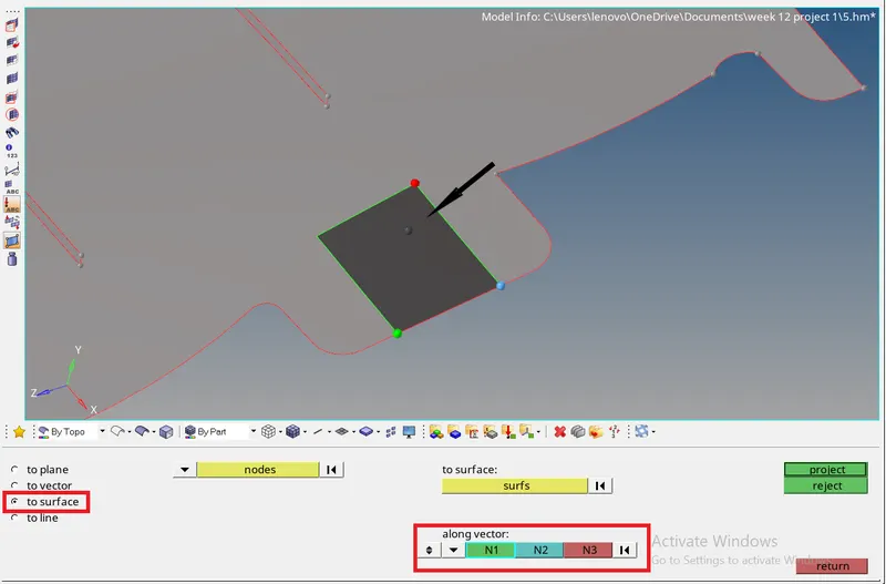
Go to tool > Project > select node > to surface > N1,N2,N3 > project.
- Now create a hole of same diameter as it is on the parent body.
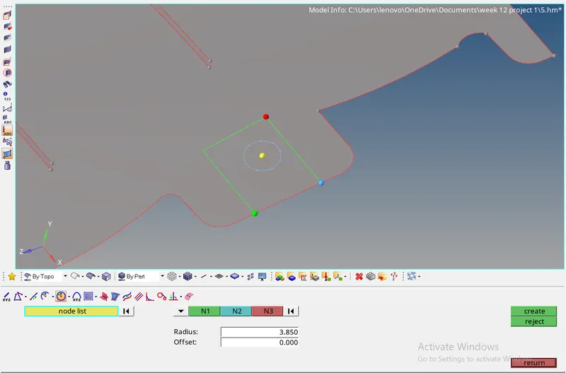
- Now trim this surface with the circular line and then delete that circular surface in order to creat hole.
Geometry > surface edit > trim with lines > select line > select surface > N1,N2,N3 > Trim
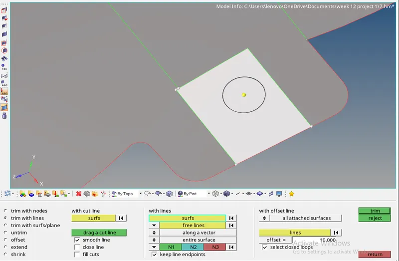
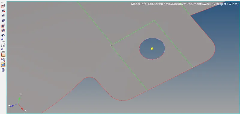
fig: Hole created
Midsurface extraction for ribs:
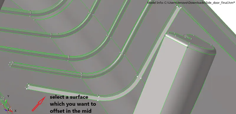
- Go to geometry > surface edit > offset > select surfaces > Distance > offset
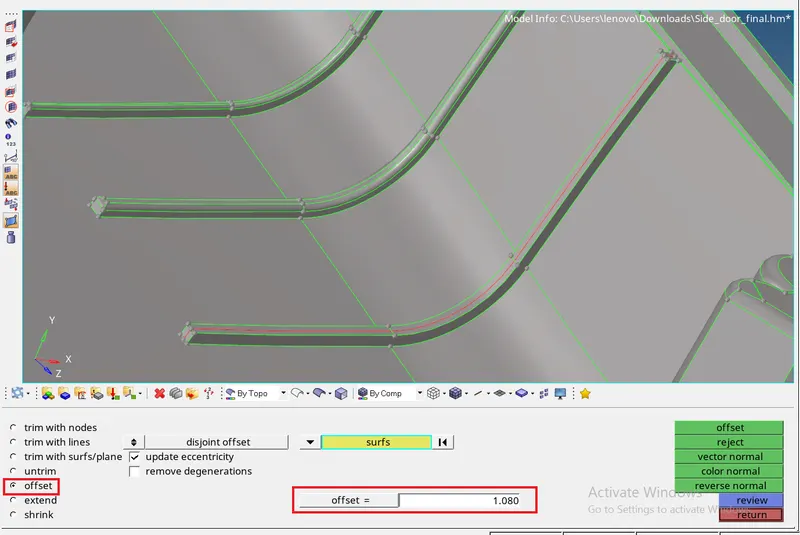
Simillarly we will be creating midsurface for all the ribs and other parts.
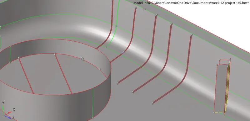
Now we will extened it over the midsurface of parentbody component 02.
- Midsurface extraction for such geometry.
1.
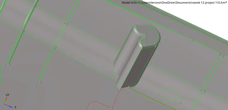
parent body
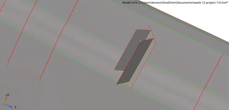
Midsurface
2.
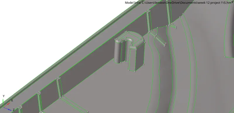
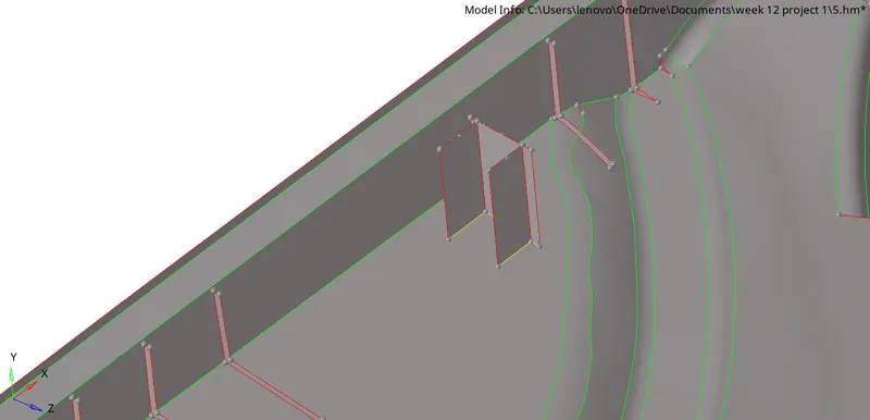
3.
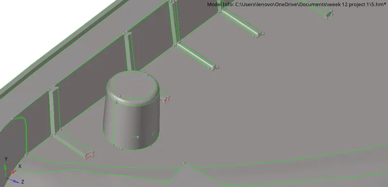
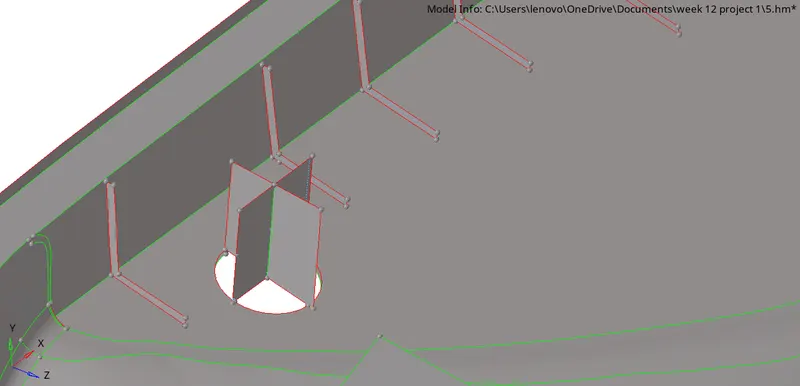
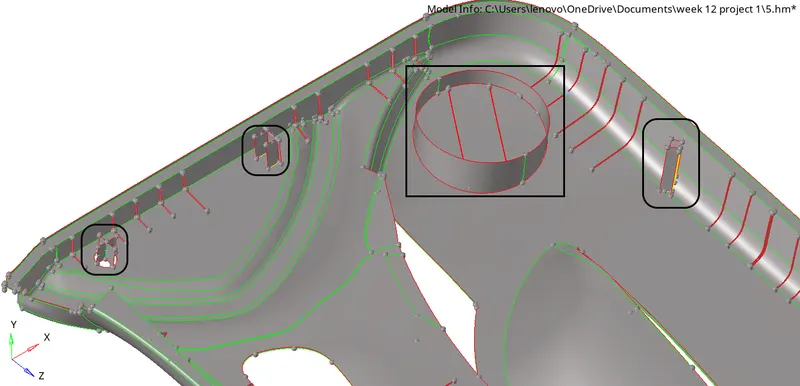
- Now we will extend all the ribs and offsetted surface over the main midsurface which is of parent body 02.
Final Midsurface:
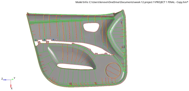
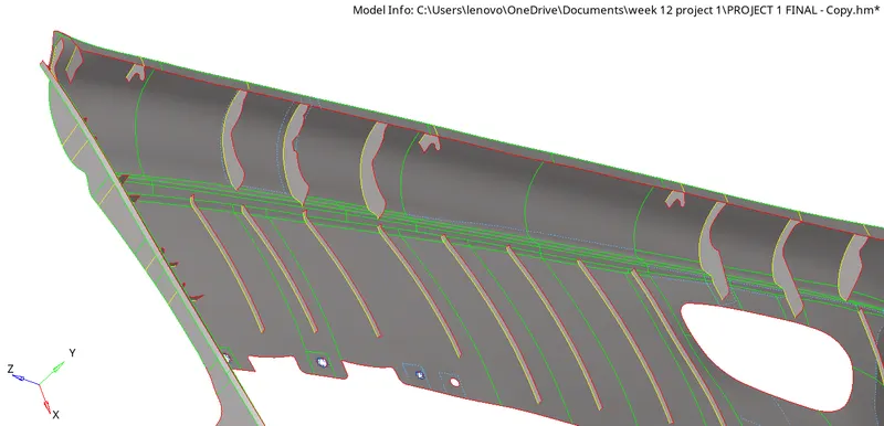
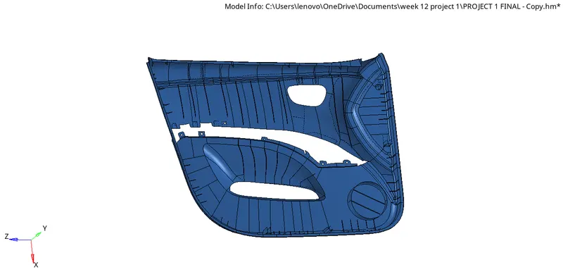
fig:By component
Stage-4: Meshing the component:
- Now we will start meshing the components part by part.
- And during meshing key points we need to take care about it.
Key points for start meshing:
- Try to provide simplest kind of mesh elements in order to avoid failure.
- Provide smoother mesh in complex areas also because ananlysis we be based on our mesh.
- Start with coarse mesh and understand the modeling results.
Given Quality criteria for this model:
Target Element Length = 4 Units
S.N. Quality criteria
1 Aspect Ratio Ratio of max lenth/min legth 5
2 Skewness Deviation from ideal shape 45
3 Warping Angle between the two planes of the same element(quad) 15
4 Min.Length shortest length of any given element 2
5 Max.Length largest length of any given element 8
6 Min. angle quad Minimum angle in any given quad element 45
7 Max. angle quad Maximum angle in any given quad element 135
8 Min. angle tria Minimum angle in any given tria element 20
9 Max. angle tria Maximun agnle in any given tria element 120
10 Tria % percentage of tria in meshef surface 10
- Set all the quality criteria in Parameter files in prferences,and start meshing.
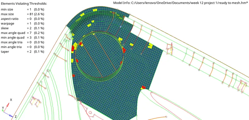
- we will clear all the failing elements using cleanup tools in the quality index panel.
Mesh flow:
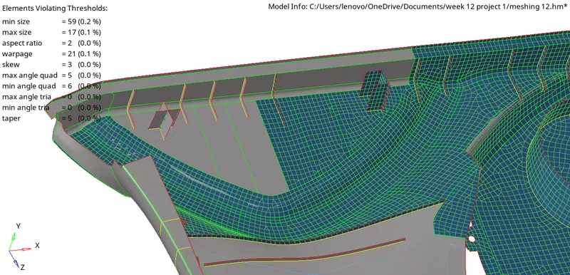
Final Mesh:
By Elemental Quality:
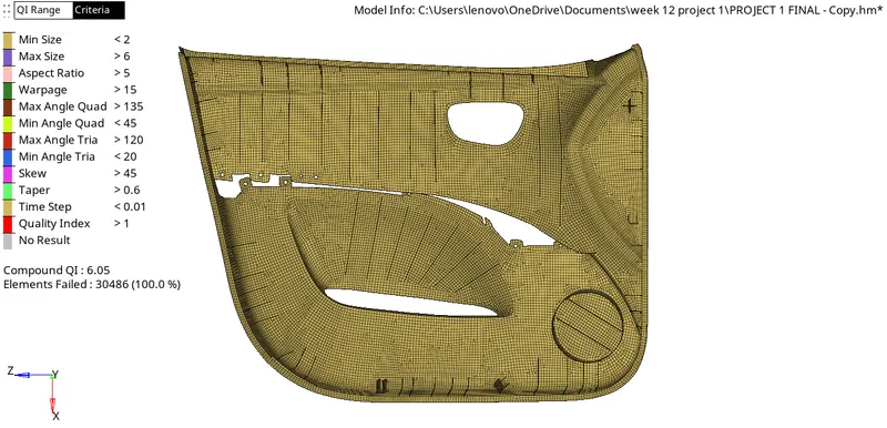
By component:
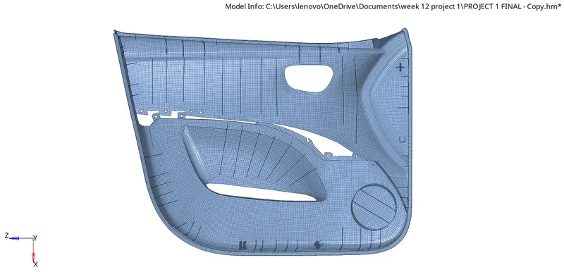
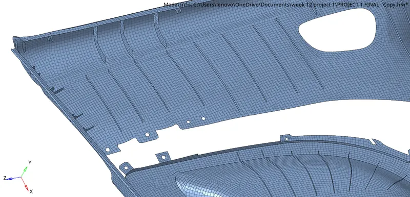
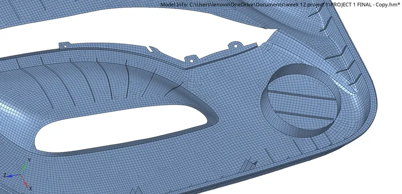
Assigning thickness to the components:
- For assigning thickness to the component first weneed to create component of different different thickness.
Go component panel > right click > create > component
- Now we need to create property and put thethickness value of indivisual as shown in below figure.
Right click on panel > create property > put thickness value
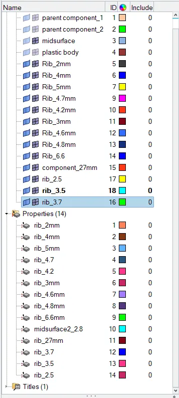
- Now we will assign the property for every indivisual component.
Right click on component > Assign > select particular thickness property.
Now this is the result after assigning the thickness with all details for all components.
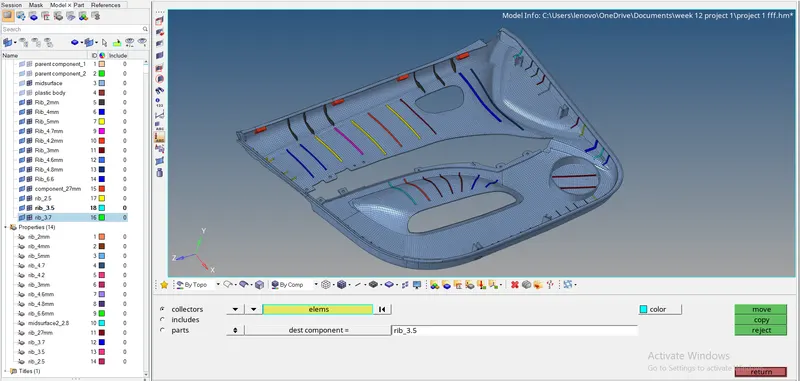
Final model By component:
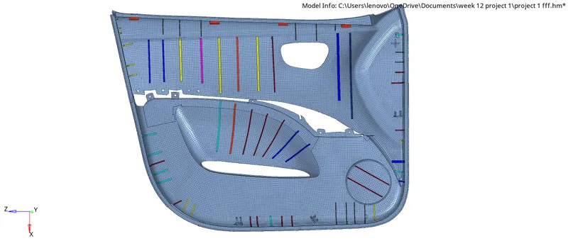
Result:
- Midsurface for this component is extracted succesfully.
- All elemental cleanup is performed with zero geometrical glitch.
- Meshing has been performed with all given quality criteria.
- All elemental failure has been resolve by cleanup tools and by many more methods.
- The feature lines have been achived.
- A good meshflow have been achived with zero elemental failure.
Learing and conclusion:
- From this project i get to know that how to extract midsurface for complex geometry mannualy also.
- How to perform geometrical cleanup in complex models.
- How to achive a good mesh flow while meshing and how to avoid elemental failure with low tria percentage.
- How finally how to assign thickness to different different components.