Week 2 Bevel Gear Challenge
Aim-
- To do deck setup for bevel gear and run the simulation to analyze the results with different materials.
Objective-
- Go for structural analysis in ansys workbench and click on engineering data to select material.
- To select material from engineering data source,for this challenge select structural steel.
- Then import the bevel gear geometry and open it in spaceclaim and fix the issue if any and close the space claim.
- Update the model by right click and and open the ansys mechanical by clicking on edit once right click on model.
- Now perform deck-setup here, give all connections,boundary condition,loads and output request for simulation.
- Then solve the model and compare the results with different cases(mesh size 4,5 and 6mm).
Step-1 :Open Ansys workbench
- Open Ansys workbench and select static structural type of analysis.
- Then go setting of engineering data to select appropriate material,in this case choose structural steel as material.
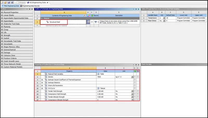
Step-2: Import cad file in Geometry and open it in space claim.To check weather cad model is fine or not,if any error will found then fix it.
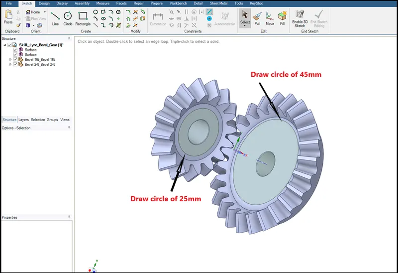
- To make it lighter weight we remove some material from it, for that draw a circle less then their dedendum circles.
- In next step use pull option and as shown below.
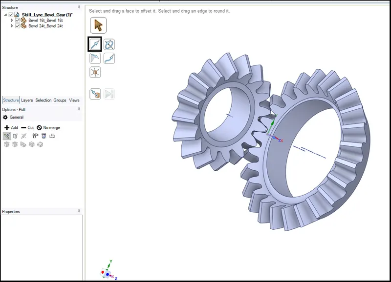
- Now close space-claim and this updated model will save automatically.
Step-3 Update model and open in ANSYS mechanical
-
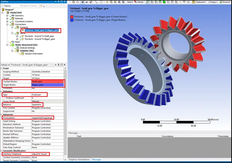
Contacts- In contact connection since this case gear tooth faces will come into contact so select faces for both gear simulteneously as contact and target.
Select all faces which will get into contact during simulation.
- Contact- Material with low stiffness/smaller gear (total 16 faces selected)
- Target- Material with higher stiffness/bigger gear (total 24 faces selected)
Then,
- After that define the contact behaviour and all other definitions.
Frictional Contact-
- Frictional contact allow frictional sliding over the surface with no seperation.Since we give positive frictional coefficient value.
- So the contact will be handle shear stress upto a limit depending upon frictional value given after that it will slide.
Augmented Lagrange-
- Using agumented lagrange it enables the contact to come out as soon as it gets into contact and avoid unnecessary chattering to reduce vibration and noise.
- It improves the stiffness of component in order to avoid penetration and chattering of meeting contacts.
Interface treatment-Adjust to touch:
- After enabling it, gaps or any kind of initilal penetration will be removed and as name suggest it follow a simple contact between surface which are going to be in conatct during simulation.
- If gaps are there then the parts might start flying during simulation,but in case pf concentric cylinder a manual offset value should be provided by user.
Step-4:Joint connection-
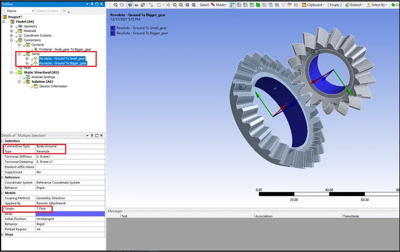
- In contact itself will define the revolute joint connection in which we will give revolute joint connection to each gear w.r.t. to ground.Because the gear is going to rotate on an axis so that here provide revolute joint for each gear w.r.t. ground.
- Now select connection type as Body to ground and type as Revolute inner radius face of gear.
- Simillary go for 2nd gear as well and create revolute join connection.
Step-5: Analysis setting-
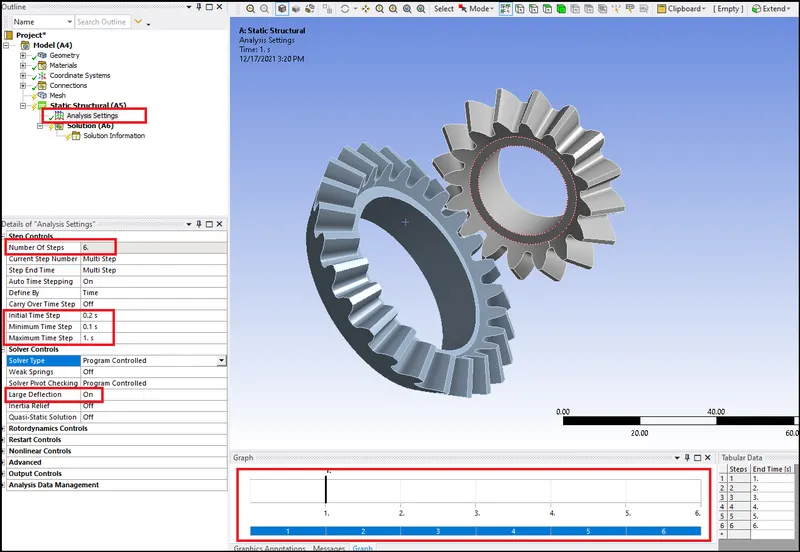
- Since we are intrested in looking all stress, strain, contact force, deformation results for one complete revolution.
- So for analysis devide it into 6 step instead of one step to see the results properly in each step.
- Now select all steps togather and define analysis setting, Keep auto time stepping to be on define it by time and give tim-step values.
- Select large deflection to be on to evaluate results for any large deflection in simulation if found.
Step-7:Apply joint load
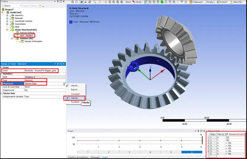
- To give joint load right click on static structural and select joint load.
- Select type as moment,
- Give moment load on bigger gear (Revolute-Ground to Bigger gear).
- Give 100 N-mm moment in each step.
- Negative value to make it clockwise, cause right gear joint load is given in anti-clockwise direction so to give proper roation both gear should move in opposite direction.
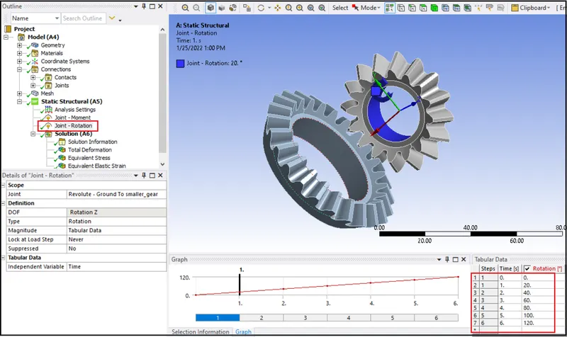
- For smaller gear Select type as rotation,
- Give Rotational joint load for right gear (Revolute-Ground to small gear),
- Give 20 degree rotation in each step in tabular data so total will be 120 degree.
Step-8: Request for output results
- For this simulation we will request output results for Total deformation, von-mises stress and equivalent strain.
- For that right click on solution and select all three option seperately.
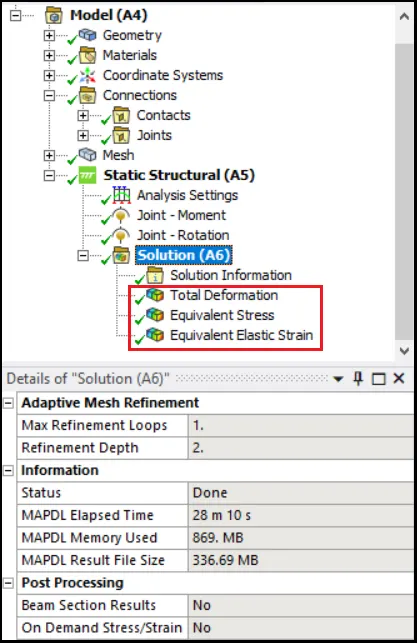
Now Hit on solve,
Right click on solution > Solve
Result Evaluation-
case-1
Von mises stress-
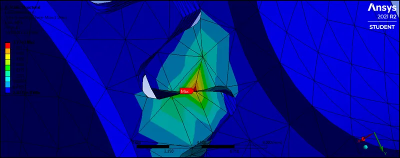
Equivalent starin-
Total Deformation-
Grid Dependency test-
- We perform grid depency in simulation is basically to get appropriate results.
- In grid dependy what we do is perform simulation on different mesh size and evaluate simulation results
- If result is seen approx same for two last successive mesh size then we accept that mesh size for final as result.
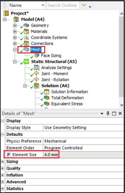
In this case intead of performing different simulation,at 1st we performed simulation at 4mm mesh size.After that we can evaluate results for different mesh size,
For that create parametric set,
Go on solution results > von-mises stress >check on P 'notation' as shown below
Since we are performing grid dependency on different mesh size so activate 'p' for mesh first.
Now activate 'p' for results,
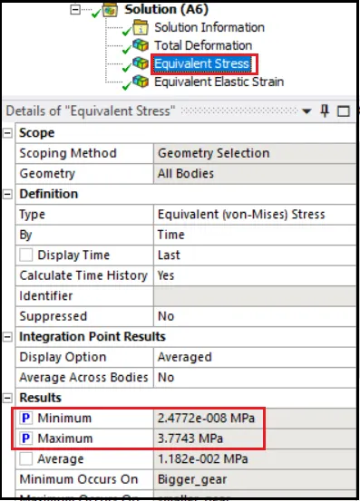
- Follow same procedure for Total deformation and equivalent strain results.
Now close Ansys mechanical.
And in workbench will can see parametric set is created now,
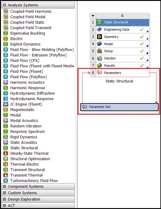
- Click on parametric set a new window will pop-up.
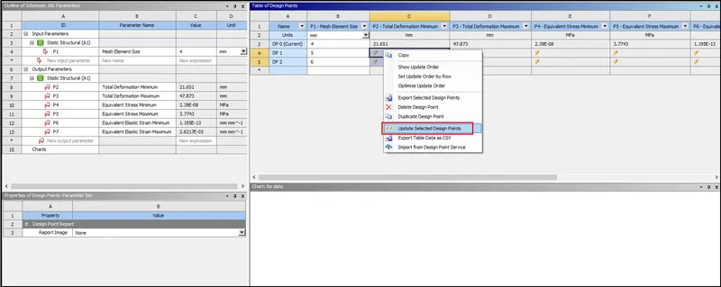
- Right click on 5,6 mm size result box and update,it will take time to evaluate results.
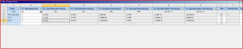
- Here we can see results for different elements sizes.
From above table we can see that the totral deformation value is same in all case.
But stress and strain values are close for 1st and 3rd case.
Maximum stress induced for 4mm mesh size is 3.7743 Mpa and for 6mm mesh size is 3.5767 Mpa .
Maximum strain induced for 4mm mesh size is 2.6217e-5 Mpa and for 6mm mesh size is 2.2972e-5 Mpa .
So if we will go with strength , 6mm mesh size is prefferable.
Conclusion-
- CAD model imported in ansys workbench and edited in space-claim.
- Created material card for strcutrual steel material.
- Model opened in ansys mechanical and performed deck set-up, boundary condition-assign contact and joint connections.
- Then meshed the model with 4mm element size.
- Defined analysis setting in 6 steps and define value for time steps.
- Then applied load conditions ie joint load (rotation and momements) for mating gears.
- Created parametric set for mesh size 5,6 mm mesh size.
- Requested for output results and then run the simulation.
- Result evaluated for all mesh cases and performed grid dependency test.