Week- 5 - Solid meshing
Aim-
- To perform 3D meshing on Car Rear view mirror using ANSA as preprocessor software.
Objective-
- To check geometrical error in CAD model of Car Rearview mirror.
- To provide mesh parameter for 2D mesh on surface.
- Deploye 2d mesh on thesurface of the CAD according to quality critera.
- Now we will creat 3D mesh [Tetra mesh] on the CAD component.
- Now we will check quality for 3D elements mainly tetcollapse.
A Brief intro to this component:
Car Rearview Mirror-
- A rearview mirror is a flat mirror in automobiles and other vehicles, designed to allow the driver to see rearward through the vehicle's rear window (rear windshield).
- In cars, the rear-view mirror is usually affixed to the top of the windshield on a double-swivel mount allowing it to be adjusted to suit the height and viewing angle of any driver and to swing harmlessly out of the way if impacted by a vehicle occupant in a collision.
- The rear-view mirror is augmented by one or more side-view mirrors, which serve as the only rear-vision mirrors on trucks, motorcycles and bicycles
- Recently, rear view video cameras have been built into many new model cars, this was partially in response to the rear-view mirrors' inability
- To show the road directly behind the car, due to the rear deck or trunk obscuring as much as 3–5 meters (10–15 feet) of road behind the car.
Procedure-
Stage 1-
Importing the model:
- Here we will ne importing the CAD file into ANSA.
- Here is many types of file format supported by ANSA for CAD model like IGES,STEP and somtimes Parasolid also depending upon the requirment of industries.
For importing the model
we will go on pull down tab >> File >> open >> select the all format >> select the model from folder
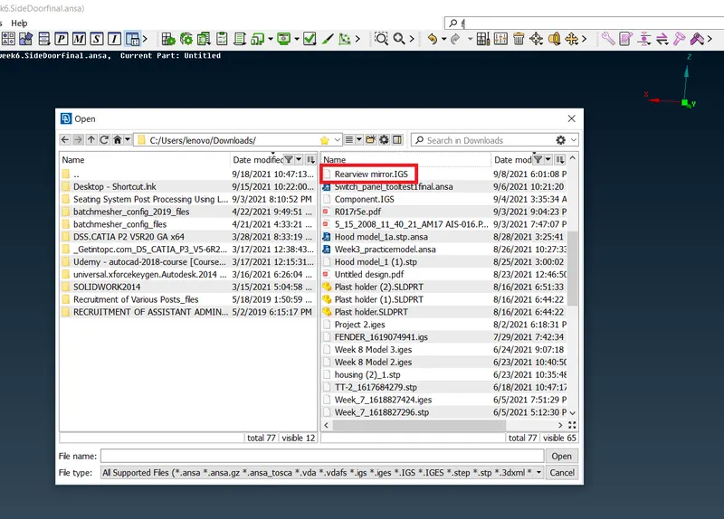
- Here is the Car Rearview Mirror model which we need to open on ansa GUI.
- As we can see here is many type of format we can import in ANSA.
Imported Model:
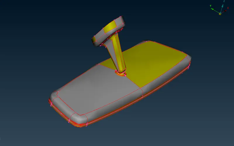
- This is the imported Rearview mirror CAD model.
- Since we use to import the CAD models in different different formats so due to softwares algorithm some geometrical changes are found after importing.
Stage-2
Manual Geometric Check and cleanup:
Before that as we can see that there are no surfaces are connected to each other beacuse we can see ther eis no single con's is shown.
- For that we have to do topo on this model.
- Then after performing topo all surfaces will get connected to each other.
- Go to topo module > Faces > Topo > Box selection for the model.
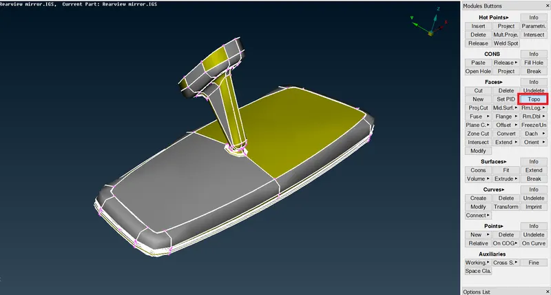
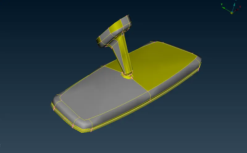
So after performing topo we should also check that is there any other errors present in the model or not such as,
- Unconnected surfaces.
- Uneccessary cons and surfaces.
- Damaged surfaces.
- Triple cons.
- Free edges.
so for that geometry check will Go to Tool bar > Check > Geometry
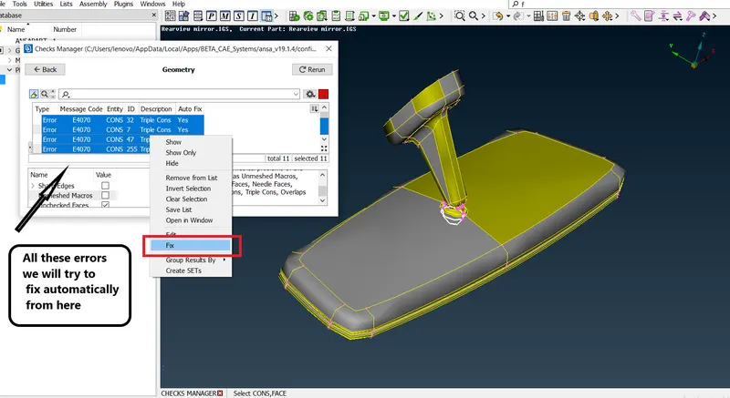
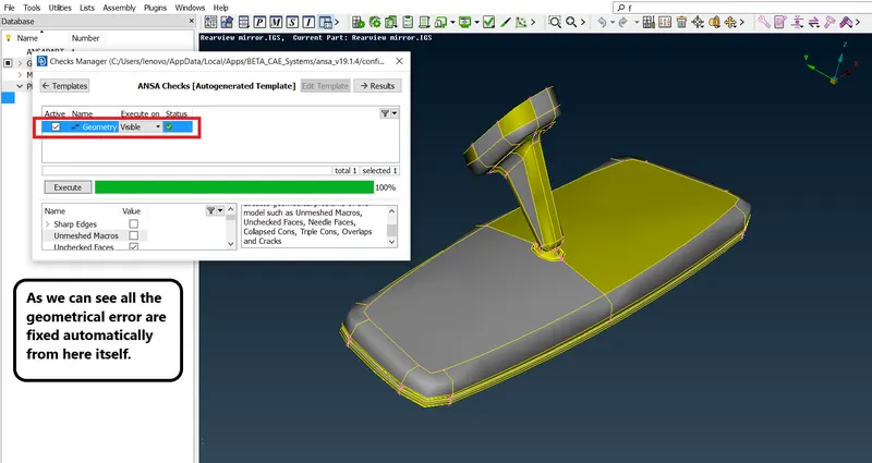
Now we can say that this model is free from every geometrical errors.Now we will move on to the meshing process.
Stage-4
Meshing:
Once geometry cleanup cleanup is completed it means there should not be any ustitched surfaces, unwanted free edges etc. Meshing meshing is next step.
A mesh is made up of elements which contain nodes (coordinate locations in space that can vary by element type) that represent the shape of the geometry. An FEA solver cannot easily work with irregular shapes
3D Meshing-
- A 3D mesh consist of finite elements with each element define with specific physical propreties.
- This 3D mesh is used for ananlysis, in various domains such as static structural analysis, dynamic model analysis, thermodynamic ananlysis etc.
- Any 3D modelled obejct with specific volume and dimension can be mehsed with thw finite no of elements that helps in solving for accuracy in pin pointing regions of strain at a higher resolution.
- We wil do 3D mesh for the components, thickness more thatn 8mm.
- Before generating the mesh give the quality criteria and mesh parameters.
Types of grid in 3D Meshing
1.Structured grid
Structured are identified by regular connectivity. The possible element choices are quadrilateral in 2D and hexahedra in 3D. This model is highly space efficient, since the neighbourhood relationships are defined by storage arrangement. Some other advantages of structured grid over unstructured are better convergence and higher resolution.
Advantage-
- Memory Efficient
- Fast to solve
Disadvantage-
- Angled or curved geometries are approximated (Leads to stair stepping)
2.Unstructured grids
An unstructured is identified by irregular connectivity. It cannot easily be expressed as a two-dimensional or three-dimensional array in computer memory. This allows for any possible element that a solver might be able to use. Compared to structured meshes, this model can be highly space inefficient since it calls for explicit storage of neighborhood relationships. These grids typically employ triangles in 2D and tetrahedral in 3D.
Advantage-
- Complex geometry easy to mesh
- Arbitary positions
Disadvantage-
- Greater memory requirment
- Slower to solve
Meshing for Rearview Mirror component-
Before meshing we will set all the quality criteria and mesh parameter. For this particular component we will set only maximum and minimum length for 2D mesh.
S.No Quality Criteria Value
1. Target/Average length 1
2. Minimum Length 0.5
3. Maximum Length 2
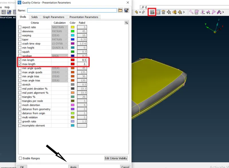
Mesh parameter-
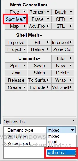
- We will set element type as ortho tria beacuse ortho tria elements are captures the surfaces and features very smoothely in 2D mehsing.
- Mostly we will provide ortho tria components on curved feature/surfaces for better mesh flow.
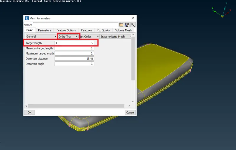
Set Perimeter and Macros length-
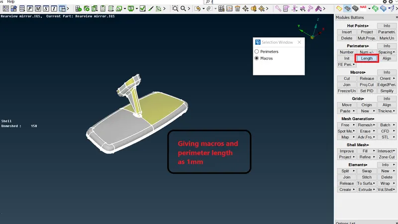
- Before meshing we should provide perimeter and macros length for better element capturing.
- Will set the perimeter and macros length according to average element length.
Go to mesh panel > Perimeter > Length > Perimeter(1) ,macros(1)
There are four components in this model:
- Spherical Bearing
- Mirror Frame
- Mirror
- Handle
We will start meshing one by one component,
Spherical bearing:
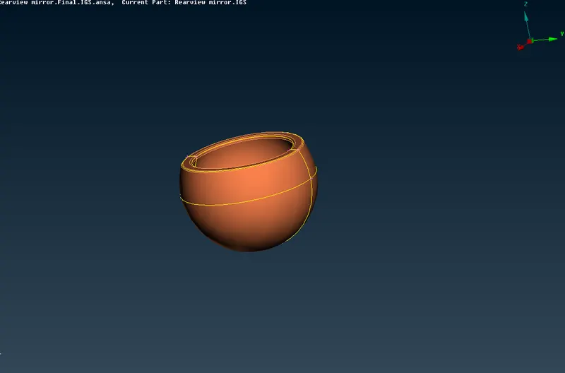
For meshing this component we will go to,
Mesh module > Mesh generation > Spot mesh (ortho mesh) > select component
As we can see here maximum surface portion of this spherical bearing is curved so for curved surface we will provide ortho trias
And on flat region we will use normal trias, which we can switch from here,
Start 2D meshing-
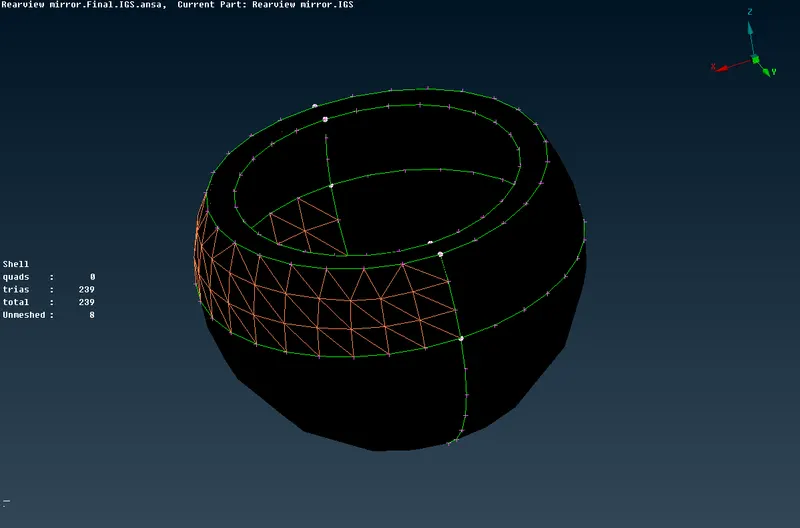
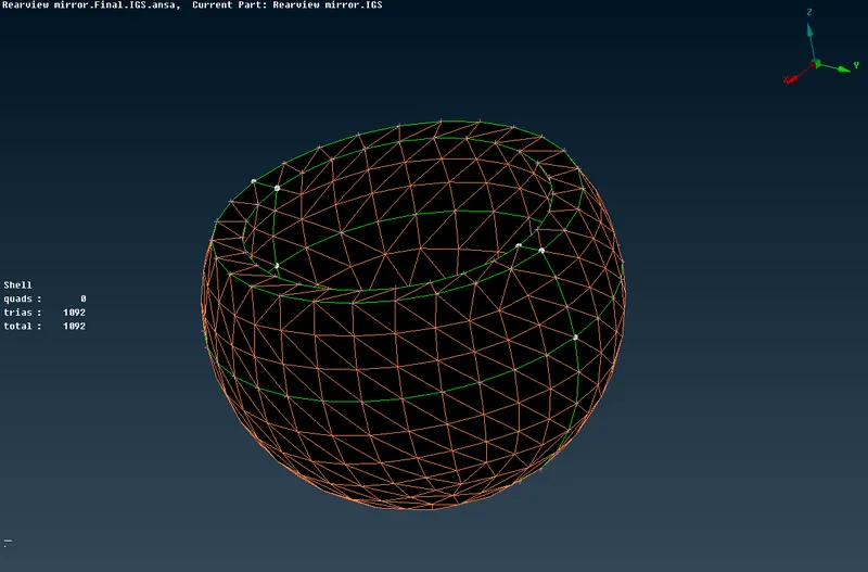
- Now after 2D mesh on surface we will convert it into volume mesh.
- Go to volume mesh module > Define > Manual > Window selection > Creat new PSolid
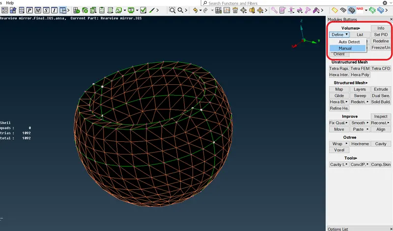
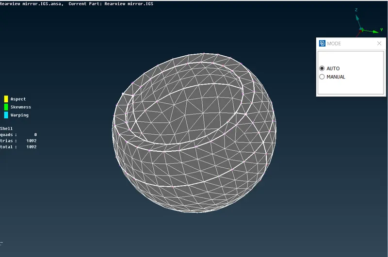
Creating new PID for PSolid:
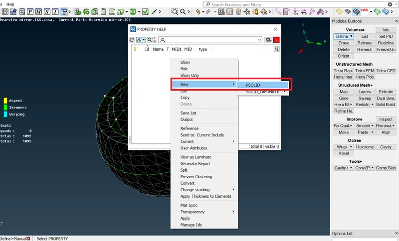
Now when we will go to check Volume list-
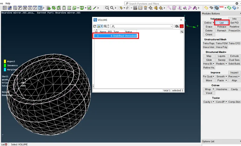
We can see one volume is created, and it shown also that this is unmeshed,
Right Click > Remesh > Tetra rapid
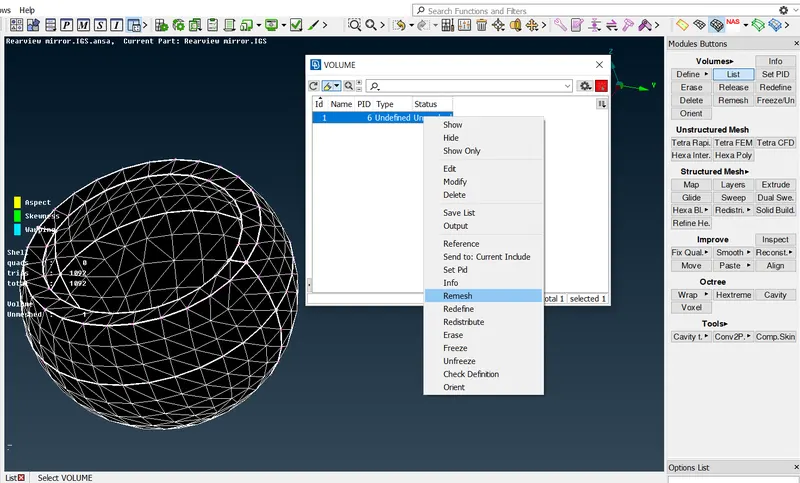
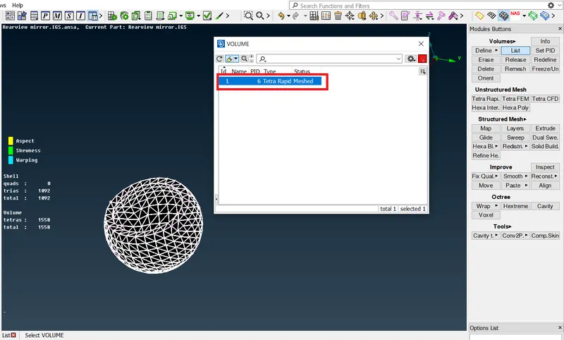
Now it is showing that this volume is meshed now.
Will see in cut section to check that volume is meshed or not.
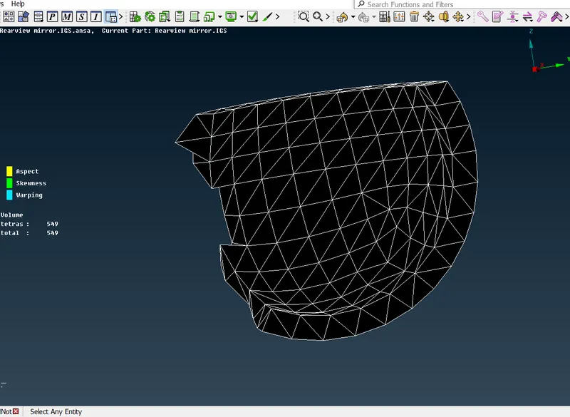
Now we can see that this volume is meshed properly with unstructured mesh.
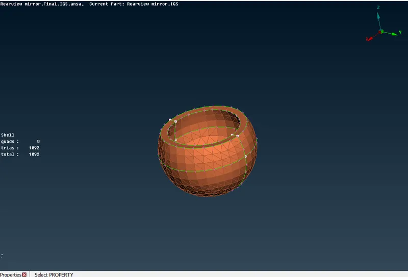
Simmilarly we will do for other components also.
Mirror Frame-
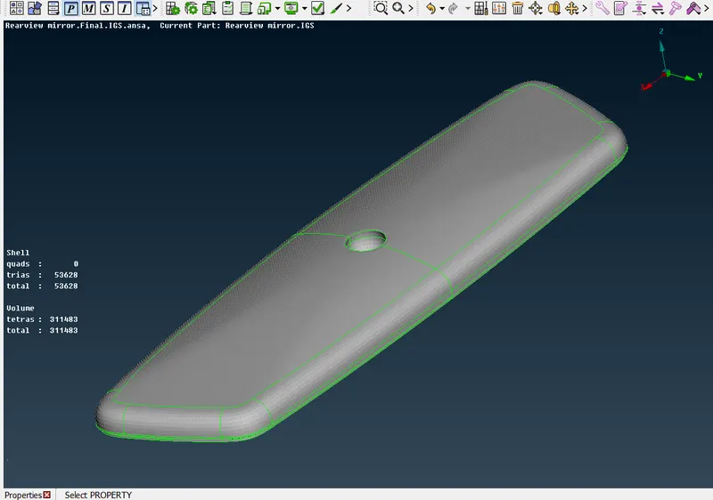
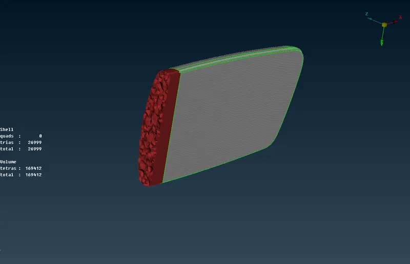
Mirror-
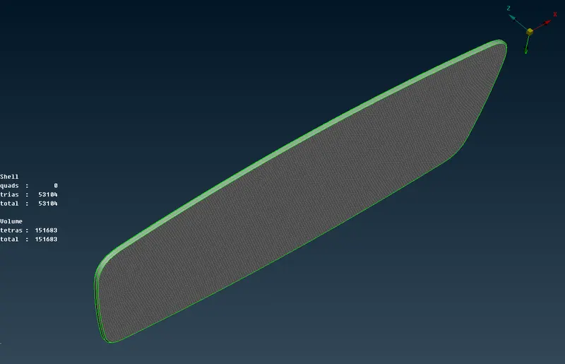
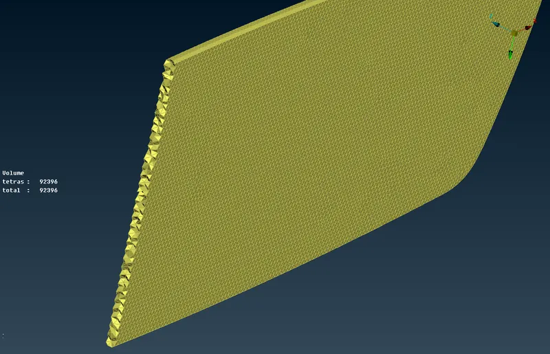
Mirror Handle-
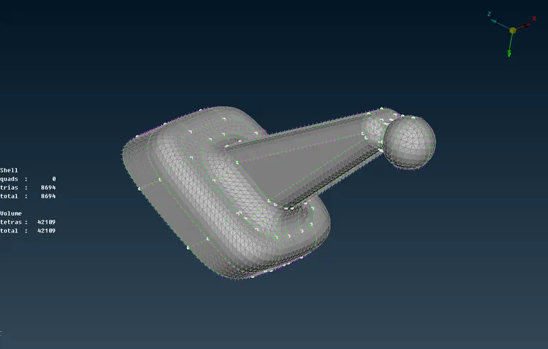
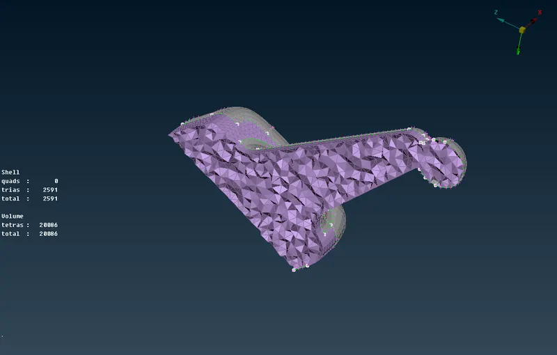
Final Model-
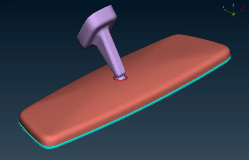
Result-
- Here we have completed 2D shell mesh conversion to 3D volume mesh.
- With all the quality criteria fulfilled for 2D and 3D elements.
- All the geometrical glitches are eliminated successfully.
- All the feature has been captured successfully and provided better mesh flow.
- A very good connectivity achived between the surfaces.
- Achived zero element failure for this component.
Learning outcome-
- We have learned all the geometric operation related to the 3D mesh for given component.
- How we should creat 3D elelments without any failure like tetcollapse, kinks, dents, raised edges.
- How ro creat volume for prforming tetramesh.
- How to fix tetcollapse failure.