Week 1 Stress Concentration on a Plate with hole
Aim-
- To perform tension test on a flat plate with holes.
Objective-
- Open Ansys workbench and select static structural analysis system.
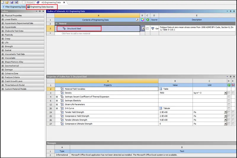
- Define the material as required, in this case we will select structural steel.
- Open space-claim and create plate with holes as per case.
- Then open space-claim and edit the CAD model in it.
- Update model in Ansys-Mechanical and perform deck setup in that.
- Set material,define connections,set analysis settings, add load and request for output files.
- Then solve and post-processed by comparing results of different cases.
What is stress concentration?
- stress concentration is the accumulation of stress in a body due to sudden change in its geometry.
- When there is a sudden change in the geometry of the body due to cracks, sharp corners, holes and decrease in the cross section area, then there is an increase in the localised stress near these cracks, sharp corners, holes, and decreased cross section area.
- The body tends to fail from these places where the stress concentration is more. So to prevent a body from getting failed, the concentration of stress should be avoided or reduced.
What is stress concentration factor?
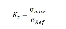
It is defined as the ratio of highest stress in the body to the reference stress. It is denoted by Kt.
Mathematically,
Where
σmax = Highest stress or maximum stress
σref = Reference stress
Methods to Reduce Stress Concentration.
There are number of ways to reduce stress concentration in a body and some of these are,
- If we have an object, that has an internal hole within it. Then the intensity of stress near that hole is more. To avoid this, some smaller holes are created near that hole. This distributes the stress more uniformly than it was before.
- If threads are in component then decreasing the nominal diameter of the shank and make it equal to the core diameter. This will distribute the stress more uniformly in the object with threads.
- By providing notches or undercuts at sharp corners.
Procedure-
Stage-1: Ansys-wrokbench setup
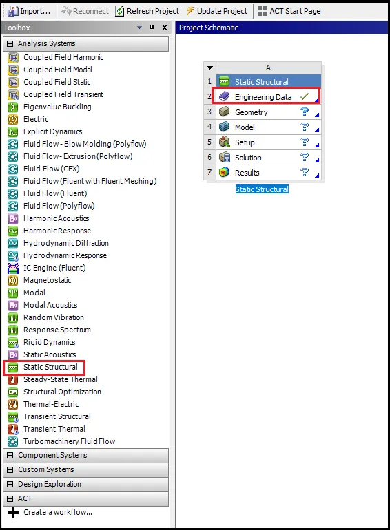
1.Open Ansys-workbench and select static structural and then click on Engineering data to select material.
- From engineering data select structural steel.
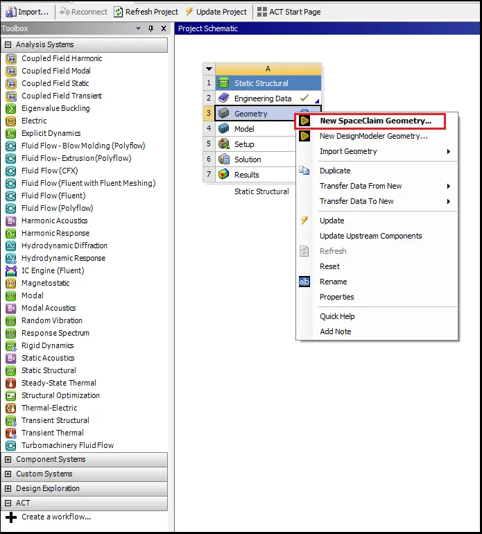
Stage-2:Open space-claim and create CAD geometry
- Now close Engineering Data tab,and create geometry in space-claim.
- Space-claim GUI is opened.
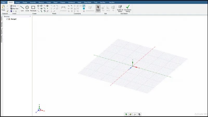
- Create rectangle using rectagle command from tool bar and give dimension for both side.
- Then create hole at the center using circle tool from tool bar.
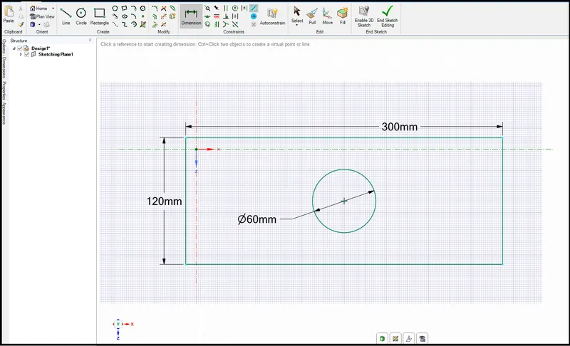
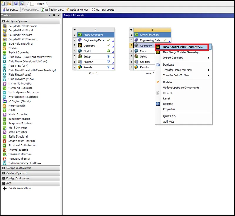
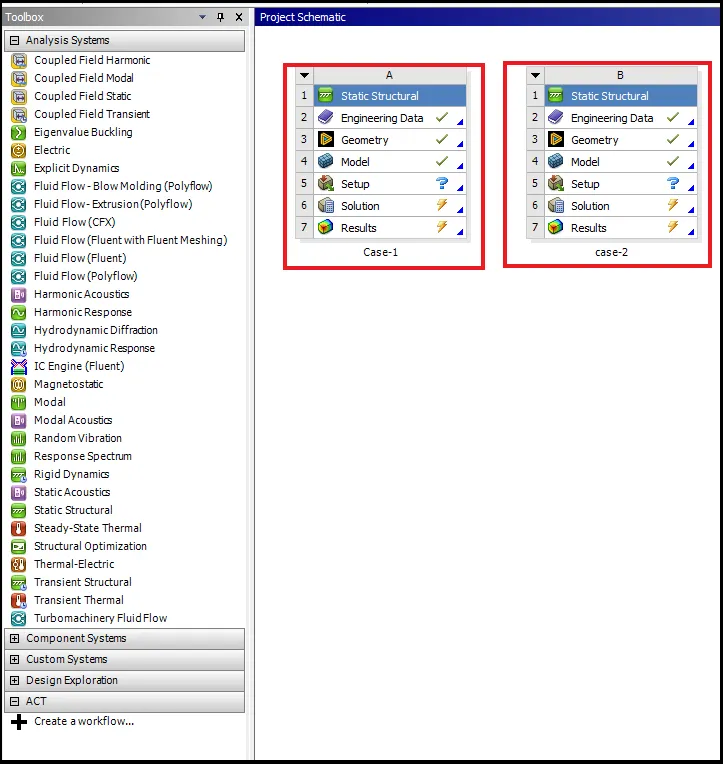
After creating geometry close space claim.Then create different static structural project for 2nd case.
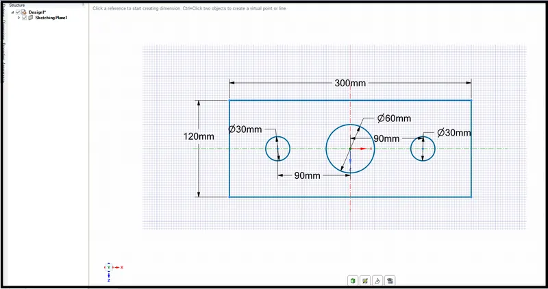
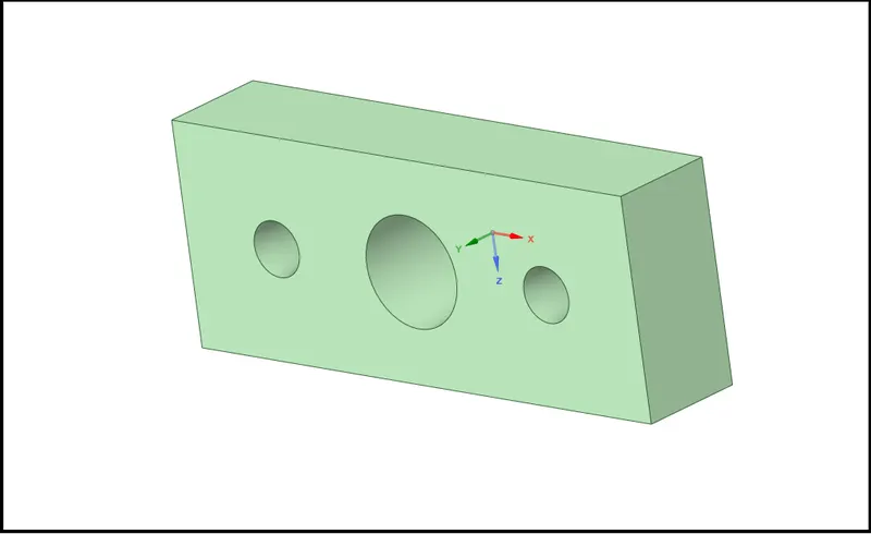
- For this case we will create two additional holes in plate.
- And using pull option will give thickness to plate,simillarly will do for 1st case as well.
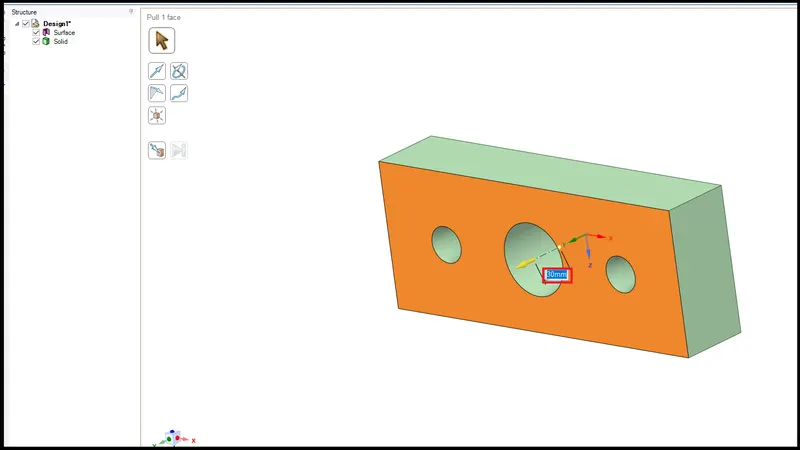
Case-2 final CAD model,
Since we have created two case, now update model for each case by right click on model and select update.
Stage-3: Open Ansys Mechanical and perform deck-setup
- After updating the model,open it in Ansys-mechanical to by selecting edit.
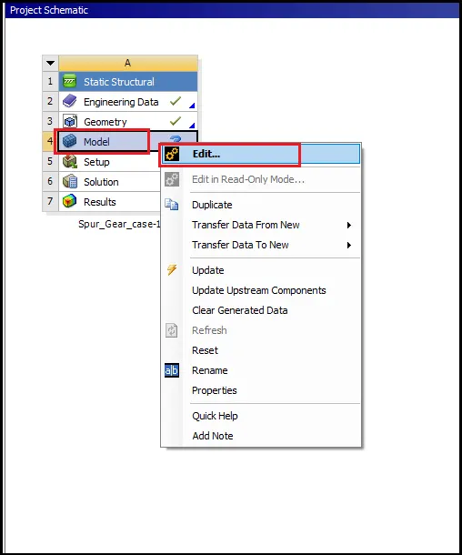
Step-1
- After opening Ansys-mechanical gor for mesh first.
- Right click on mesh and click on generate mesh before that input value for element size as 2mm.
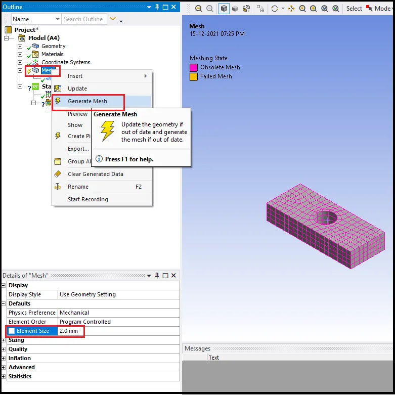
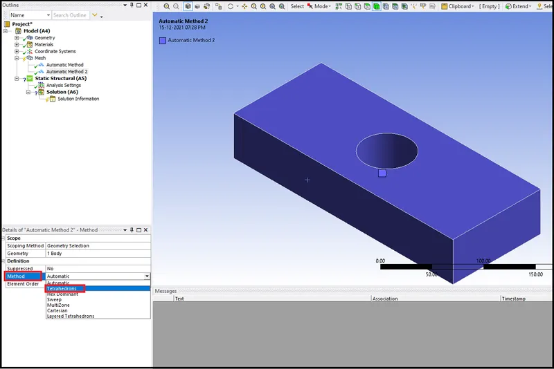
- Since it is hexa elements and mesh is also coarse,so to change it to tetra elements and to refine mesh, right click on mesh>insert>method and from method select terahedron.
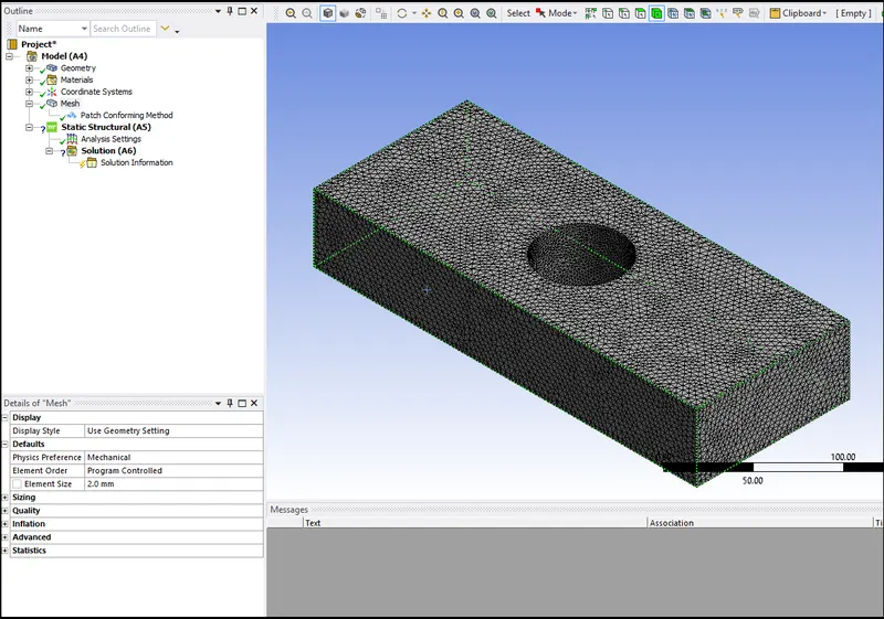
- Then again right click on mesh and generate mesh
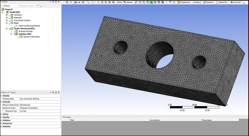
- Similarly mesh CAD model for 2nd case as well.
Step-2
- Now give loads on the model,
- Since in this case one side have to be fixed and pull force from another side.
- For fixing one side Right click on static tructure>Insert>Fixed support.
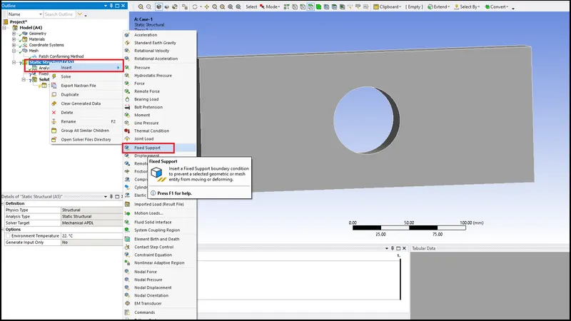
- Select face which need to be fix and click on apply.
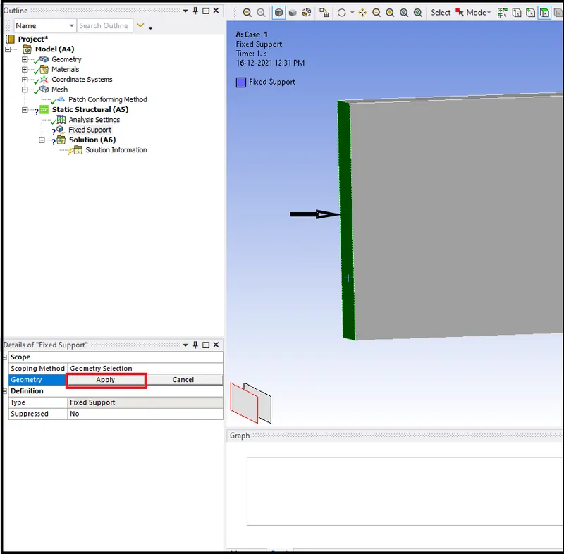
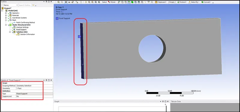
Plate is fixed now from that side.
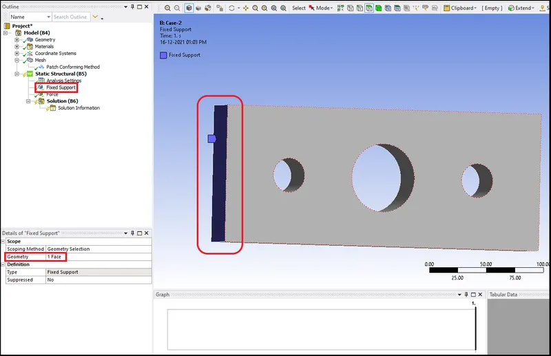
Similarly fix model from one side for case-2 as well.
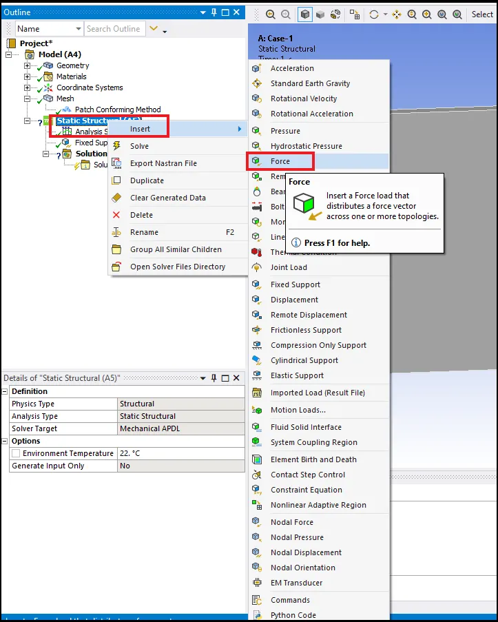
- Now deploy force load on different side,
- For that right click on static structural > insert > force.
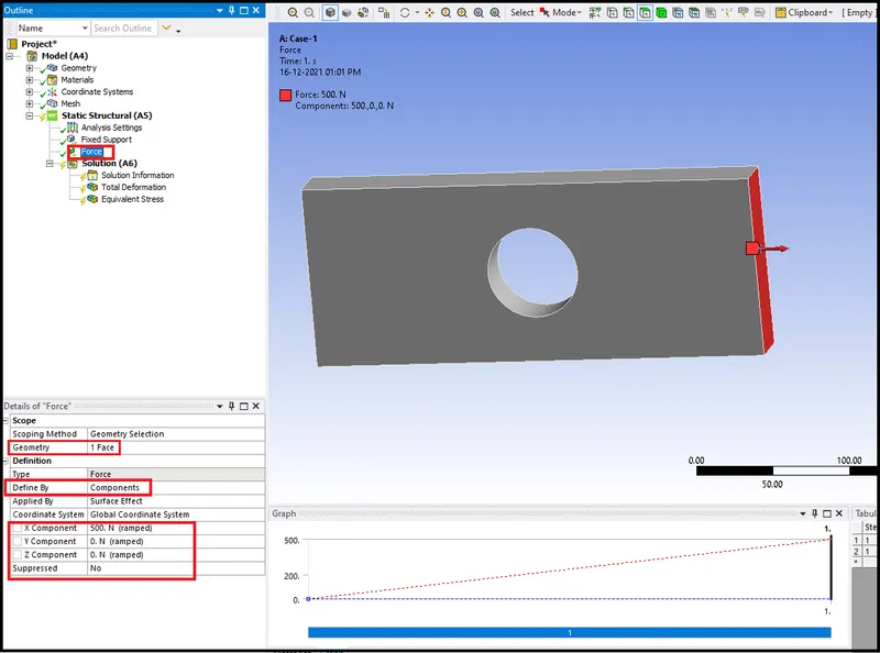
- Select face on which force to be applied.And put the value of force as 500N in +ve x direction.
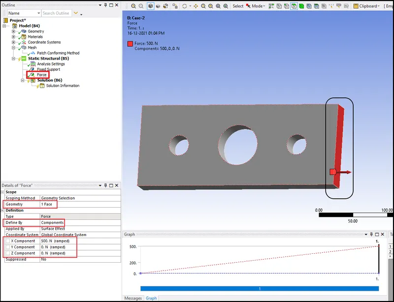
- Similarly add load for 2nd case.
Step-3
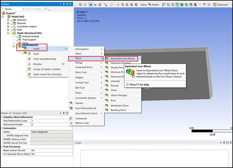
Request for solution results:
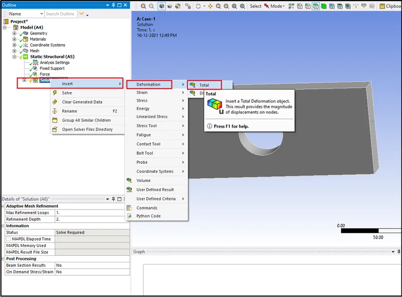
- Right click on solution > insert > deformation > total.
- Similarly request for von-mises stress and strain value.
Step-4
Solve the model:
Right click on solution > solve
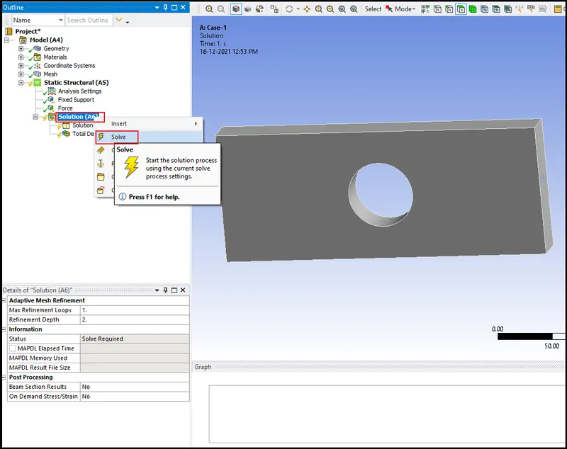
- It will take few minuts to solve the model and running the simulation we can check fir results.
[Note- Similarly request for solution and solve the model for 2nd case]
Step-5
Solution Analysis:
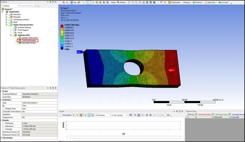
a).Total deformation
Case-1 Total deformation
Case-2 Total deformation
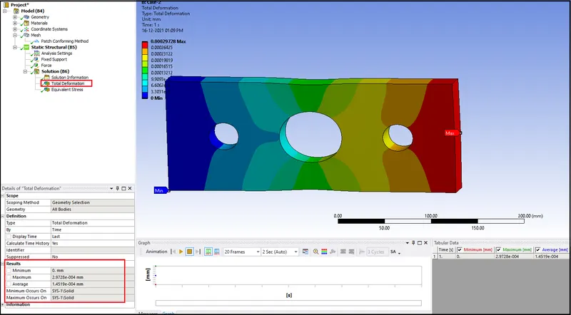
- From the above deformation results we can conclude that using multiple hole will result in increase of deformation after applying same load which acted on same plate with less number of holes.
- So from maximum deformation criteria case-1 is better than case-2.
- Mian reason behind this deformation is larger dia hole which should be avoided.
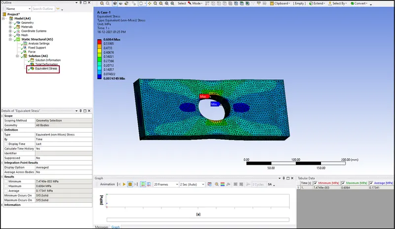
b).Equivalent stress
Case-1 Equivalent stress
Case-2 Equivalent stress
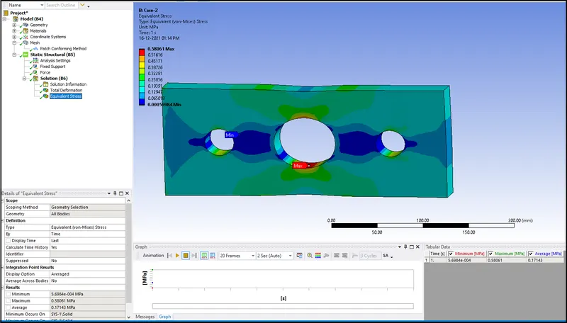
- From the above equivalent results we can conclude that using multiple hole can reduce stress and strain value which can be helpful in maintaing te component life.
- So in order to minimize the stress concentration on the complex components small dia holes preffered by industry and avoid large dia holes which can cause large deformation in component.
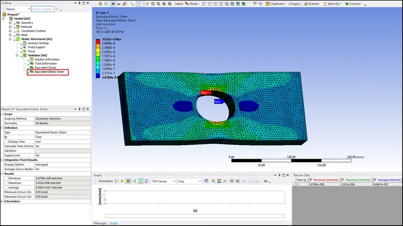
c).Equivalent strain
Case-1 Equivalent strain
Case-2 Equivalent strain
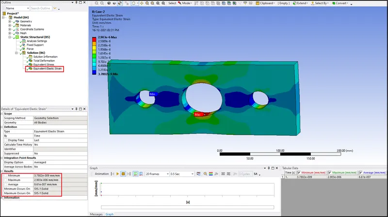
- Strain value is also decrease significantly by using of small dia holes.
Result comparison:
| Cases | Maximum Displacement | Max Equivalent stress | Min Equivalent stress | Max Equivalent strain | Min Equivalent strain |
| Case-1 | 0.0002749mm | 0.6064 | 0.007474 | 3.032e-06 | 3.8789e-08 |
| Case-2 | 0.0002972mm | 0.5804 | 0.0005698 | 2.903e-06 | 3.7802e-09 |
Conclusion:
Being a Design Engineer:
- Being a design engineer one should go with case-2 cause which helps in reducing stress concentration.
- And this helps in improving the components life without compromising its functionality.
- In further iteration larger dia holes holes can be replaced by smaller dia holes which give more relief from stress concentration.
Being a Manufacturing Engineer:
- Being a manufacturing engineer one should go with case-1 because it consume less time and cost to manufacture.
- Since in case-2 there are additional holes which cause increase in overall labour cost,material and time to manufature this component.
In this project we just comparing two cases in two different prespective,But the final decision will totally depend upon the client requirment and type of application of that component.