Week 12:Project 2-Meshing of Rear Wheel Holder challenge
Aim:
- To perform preprossecing in Rear Wheel Holder sheet metal component (Spare wheel Floor Panel) using hypermesh software as preprocessor.
Objective:
- To generate midsurface for this component manually and clean the geometrical glitch over this model
- Then to mesh the midsurface with proper mesh flow as per given quality criteria.
- Will try to mesh the component with lower tria concentration in this model.
- Then to check and clean the elements which are failing within given quality criteria.
- To assign thickness to the component.
Theory:
- The stepney spare wheel is invented Thomas Morris Davies in 1904, at that time time early motor cars were made whithout spare wheels, so a punture was an invent dreaded by all drivers.
- So Mr Davies brilliant idea was to make a spokeless wheel rim fitted with an inflated tyre.
- A spare tyre or stepney is an additional tire/tyre carried in a motor vehicle as a replacement for one that goes flat, has a blowout, or has another emergency.
- A structural shear panel for forming floor panel for support by a vehicle frame is formed by a composite of topn and bottom sheets and core with the vacuum infused resin.
- The core is formed of top and bottom layers each formed from a honeycomb panel defining an array of hexagonal tubular cells with wall which extended in the thickness direction filled with a foam material
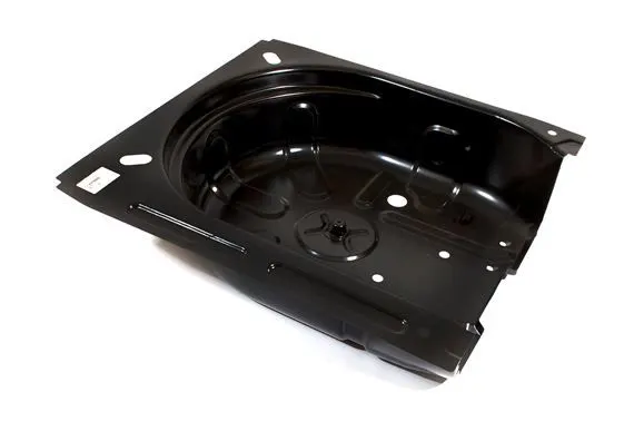
About this component-
- The component which is given to us is a car stepney spare wheel floor panel.
- This is a sheet metal component.
- For the plastic and sheet metal component with the thickness less than 6mm at this case we have to take a midsurface in order to mesh the component.
- Sheet metal is a metal formed by an industrial process into thin, flat pieces, sheet metal is one of the fundametal forms used in metal working.
- And it can also be deformed into various types of shapes.
- Countless everyday objets are fabricated from sheet metal.
- Thickness can vary significantly, extremely thin sheets are considered as foil or leaf.
- And pieces thicker than 6mm are considered as plate steel or Structural steel.
PROCEDURE:
Stage 1- Importing the model:
- Since we are importing the CAD file model in this challenge.
- So there are many type of file like IGES,STEP and parasolid we can use if we are importing a file into any CAD and CAE software.
But here in hypermesh we can use only three kind of file format:
- IGES(Initial Graphics Exchange Specification).
- STEP ( Standard for the Exchange of Product Model Data).
- SolidWorks.
Now these time most of the industries started working parasolid file formate also.
[Note: While importing the file into graphical user interface be sure that whether the file is .step or .iges file. Otherwise we will face difficulty during importing the model.]
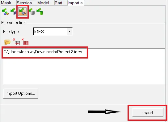
Tool we use to import in the way: File >> Import >> Import Model >> File type >> Open File.(As shown in below picture)
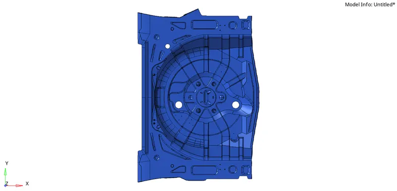
Imported model into GUI-
By component:
Front view:
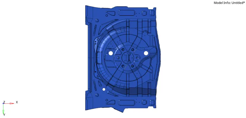
Back view:
Examine the model-
- Now we will check for the solid body after converting it into by topo model.
- After putting the model in by topo mode.
- If model is having solid then it will show in green color.
- For deleting the solid Go to delete panel (F2) > select solid > select by displayed > Delete.
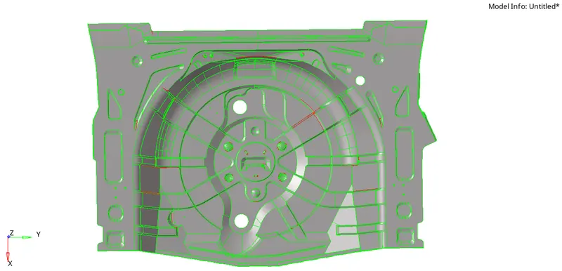
- But as we can see there is no solid when we out the model on topo mode also.
- So there is no need to use of delete panel.
Stage 2- Geometry cleanup :
So after importing the model we will go for check the model for any geometrical glitch like,
- Unnecessary surfaces.
- Free edges.
- Damaged geometry.
- Unwanted connection between surfaces.
- There are some free edges and geometrical glitch in the parent body so we need to fix it first then after we can extract proper midsurface.
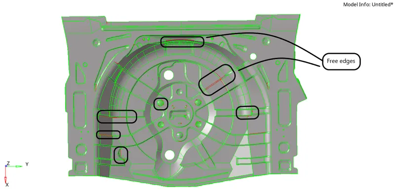
fig-Free edges in parent body
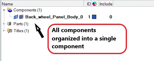
- When we observe we can see that there are 17 component in this model.
- So now we will try to organize all thos components into a single component for ease.
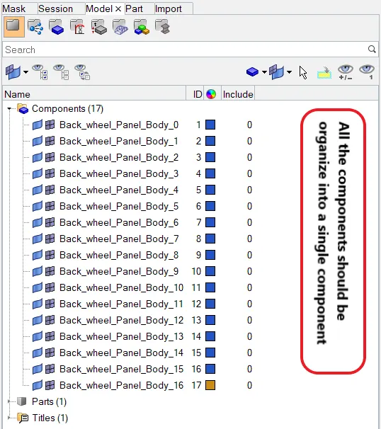
Organizing the components:
- We will go to the tool panel and from where we will slelect the organize option.
- And then select on collector and then and then select the surfaces by collector then it will show all the collector.
- Usually we can organize lines and elements etc.
- So now we will check all the components except first one because we have to organize all of them with this as shown below picture.
- And then select the destination component on which we have to organise.

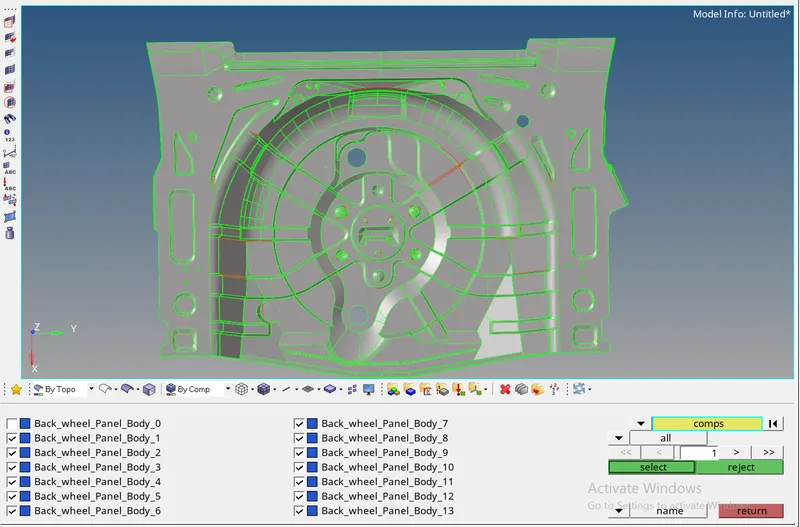
Thickness Measurment:
- Now before extracting the midsurface we will check the thickness for whole component.
- Whether the thickness is uniform or not so that midsurface extraction will be easy.
- If thickness is uniform then we can use auto midsurface extraction otherwise we will follow manual offsetting methode.
- So here in hypermesh there are two type are available to measure the thickness of the component, one is by dimensioning methode and another is direct measuring the distance between points.
- Dimesioning:
Geometry > Dimensioning > select points
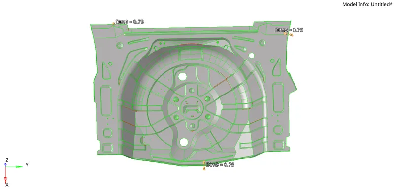
As we can see dimension at each points are equal as 0.75 so we can consider it as uniform thickness.
2. Tool (F4) > Two points > Select point1 and point2
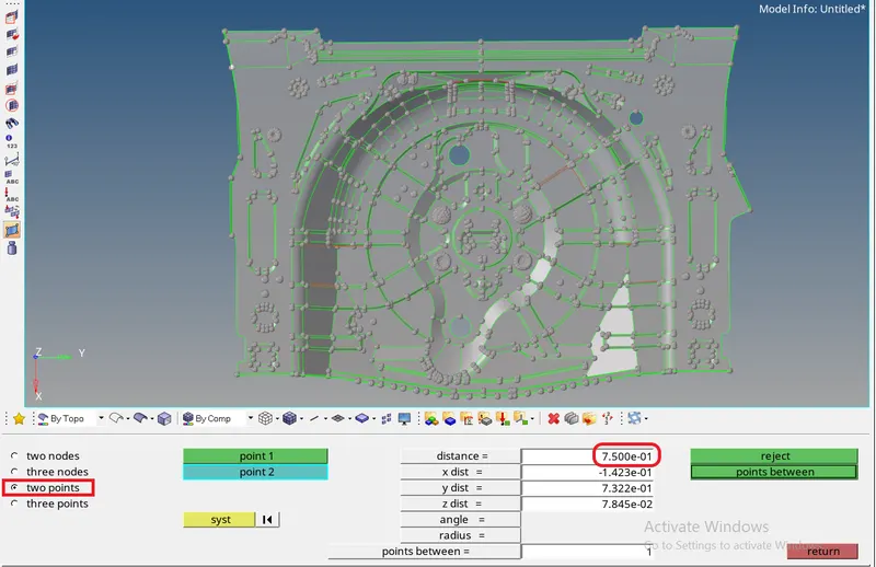
By this metode we also checked at every portion of this component and we found that the thickness is 0.75units, so we can consider it as uniform thickness.
Performing Geometrical cleanup on the parent component:
In this case we will try to avoid to perform geometry cleanup on the parent geomtry because if we will do it on parent geometry then it may take more time becasuse at the end we need to work on midsurface also.
Damaged on Geometry can be:
- Free edges
- unnecessary surfaces
- Overlaping of surfaces
- unnecessary connections
- connectivity error
1. Unnecessary surfaces:
Here is some unnecessary surfaces are formed during importing of model so first we will delete this surface.
Go to Geometry > Quick Edit > Delete Surface > Delete surface
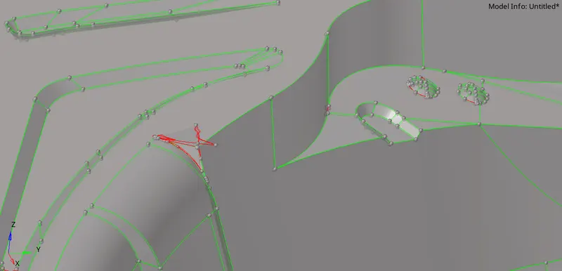
Fig - Surface Glitch found
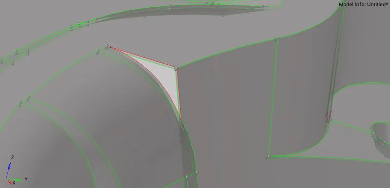
Fig- Surface Glitch Deleted
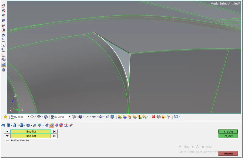
Fig-Formation of surface using ruled method
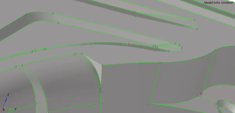
Fig- Surface formed
2. Replace Edge Sub-panel :
For this kind of surface glitch we need to use replace the edges.
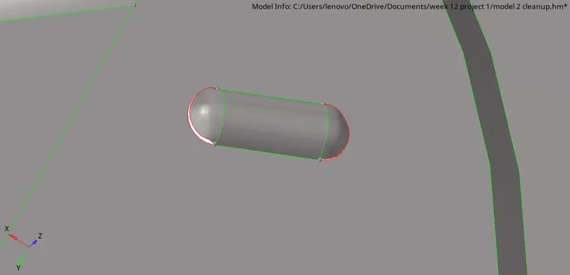
Fig- Free edges

Fig- Edges Replace sub-panel
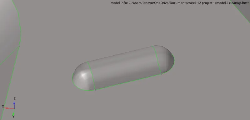
Fig- Edges are Replaced
3. Spline Sub-panel:
Some surfaces are got deleted so we need to fill it but as it is a curved surface so we will fill it by using spline sub-panel.
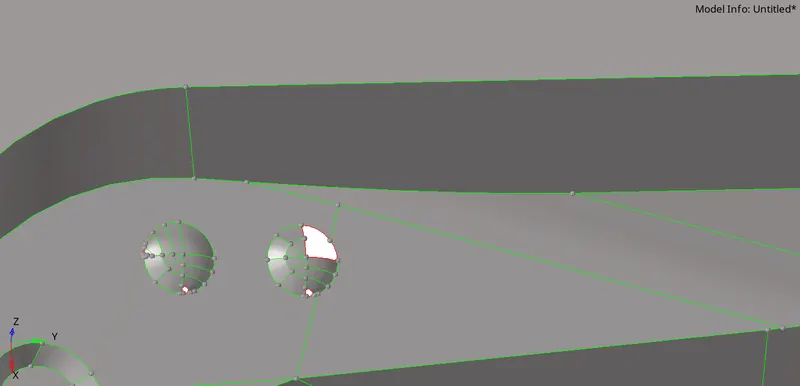
Fig- Unfilled Gap
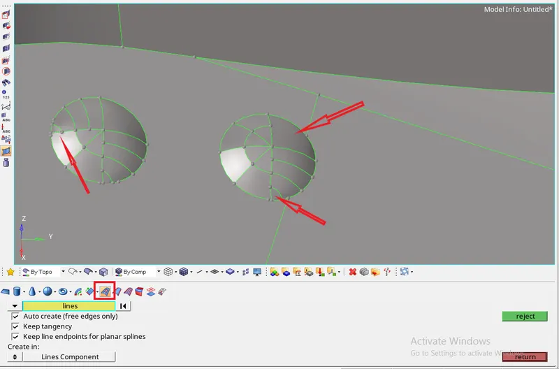
Fig- This is how we use spline methode
4. Delete Small Holes:
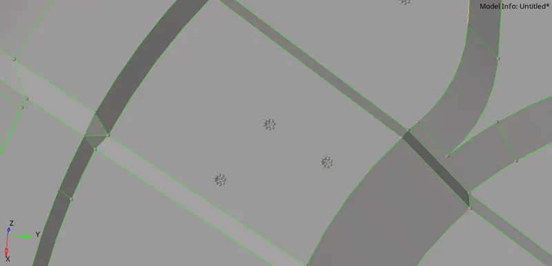
Fig- small holes in surface
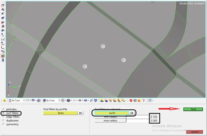
Fig- Defeaturing small holes
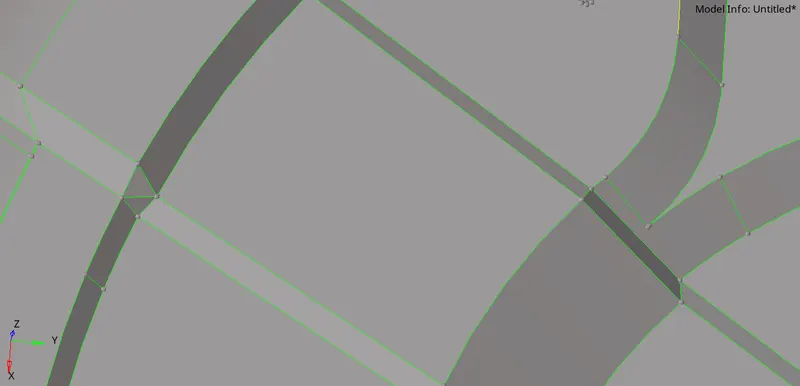
Fig-Holes are Removed
Stage-3
Midsurface Extraction :
- In this model as the thickness of the whole model in uniform so we will perform the auto midsurface extraction.
- For that we will go to the Auto-midsurface panel and select all the surface at a time and do extract the midsurface.
Goemetry > Midsurface > select on automidsurface > select the type of extraction > extract
Extracted midsurface:
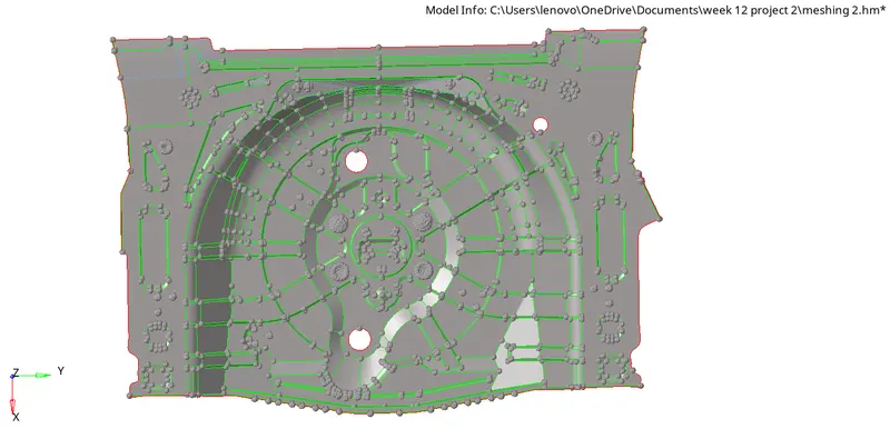
Fig-Midsurface Topo mode
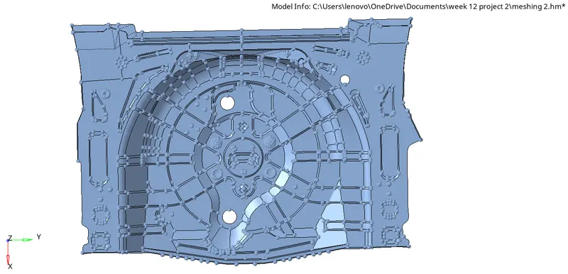
Fig-Midsurface by component
Stage-4
Meshing the component:
- So now we will start meshing the component according to the quality criteria given to us for this model.
- After that we will check for failing elements also and try to remove all failing elements using cleanup tools sub-panel and also by remeshing and many methods.
Key points for start meshing:
- Try to provide simplest kind of mesh elements in order to avoid failure.
- Provide smoother mesh in complex areas also because ananlysis we be based on our mesh.
- Start with coarse mesh and understand the modeling results.
Given Quality criteria for this model:
Target Element Length = 5 Units
S.N. Quality criteria
1 Aspect Ratio Ratio of max lenth/min legth 5
2 Skewness Deviation from ideal shape 45
3 Warping Angle between the two planes of the same element(quad) 15
4 Min.Length shortest length of any given element 2
5 Max.Length largest length of any given element 8
6 Min. angle quad Minimum angle in any given quad element 45
7 Max. angle quad Maximum angle in any given quad element 135
8 Min. angle tria Minimum angle in any given tria element 20
9 Max. angle tria Maximun agnle in any given tria element 120
10 Tria % percentage of tria in meshef surface 10
- Set all the quality criteria in Parameter files in prferences,and start meshing.
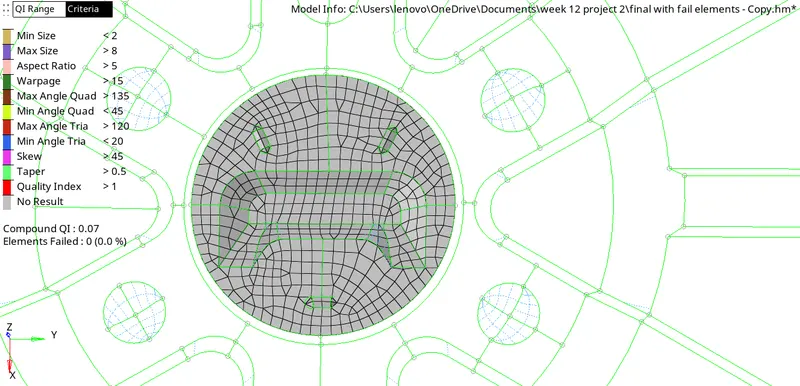
Fig- started Meshing of middle surface
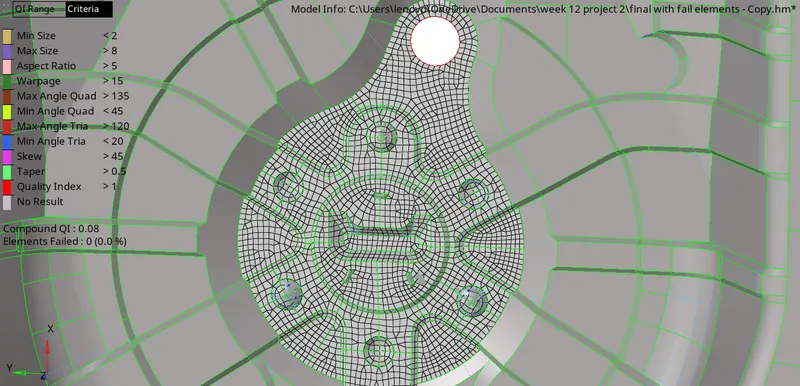
Elemental Quality checks:
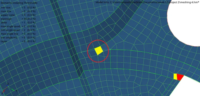
- Here we will use spliting of quad elements to avoid failure due to warpage angle.
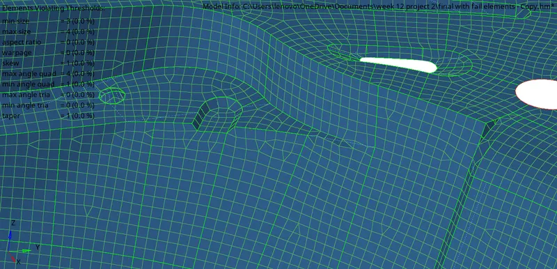
Some complex region:
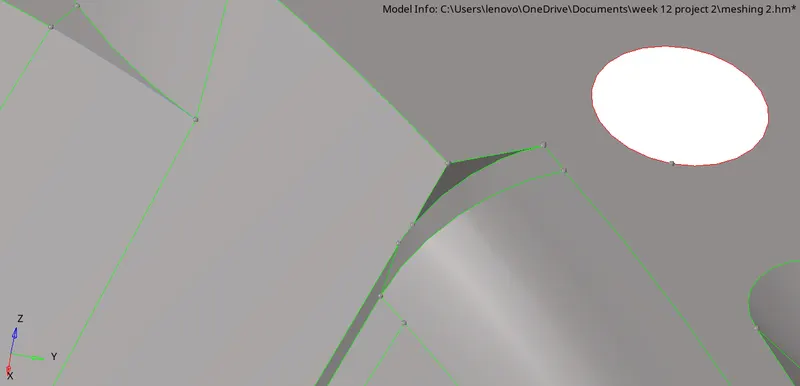
- Now we will split this surface in the maner shown below to get proper mesh flow.
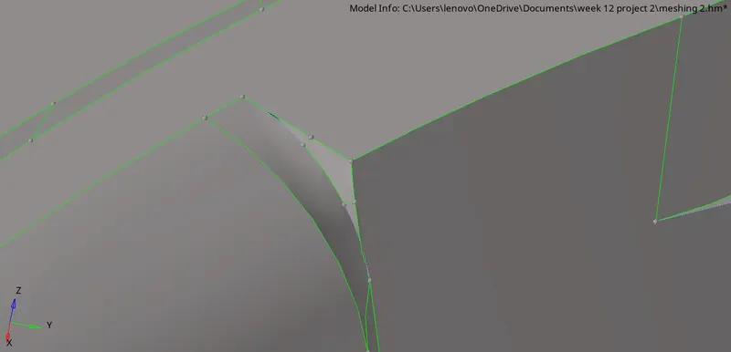
fig- Surface splitted
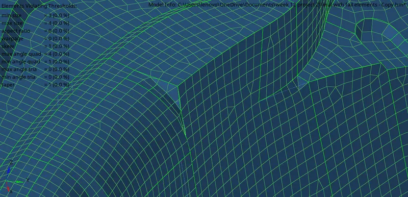
Fig- Surface meshed
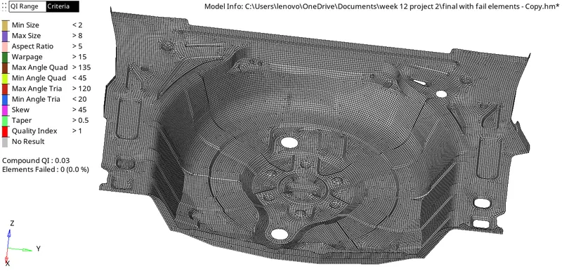
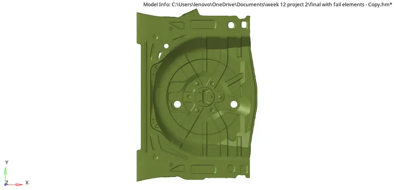
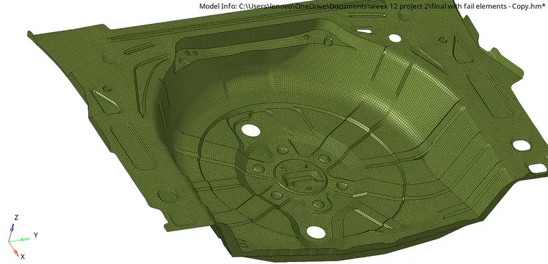
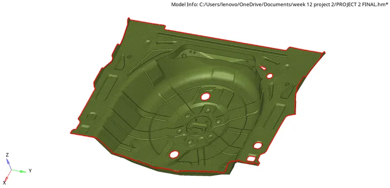
Final Meshed Model:
Geometry:
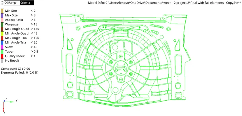
Meshed Model:(By Elemental Quality)
By component:
With edges:
Stage-5:
Assigning thickness to the components:
- For assigning thickness to the component first weneed to create component of different different thickness.
Go component panel > right click > create > component
- Now we need to create property and put thethickness value of indivisual as shown in below figure.
Right click on panel > create property > put thickness value
Here thickness we have to provide is 0.75mm.
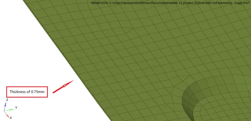
Fig- Whole Component Thickness Represenatation
Result:
- Midsurface for this component is extracted succesfully.
- All elemental cleanup is performed with zero geometrical glitch.
- Meshing has been performed with all given quality criteria.
- All elemental failure has been resolve by cleanup tools and by many more methods.
- The feature lines have been achived.
- A good meshflow have been achived with zero elemental failure.
Learing and conclusion:
- From this project i get to know that how to extract midsurface for complex geometry mannualy also.
- How to perform geometrical cleanup in complex models.
- How to achive a good mesh flow while meshing and how to avoid elemental failure with low tria percentage.
- How finally how to assign thickness to different different components.