Week 9-Creation of 1D Connectors Challenge
Aim:
- In this challenge we will creat different type of 1D connectors.
- Along with considering the quality criterias as given for this challenge.
Target Element size - 5 Units
SN. Quality criteria value
1. Aspect Ratio 5
2. skewness 45
3. Warping 15
4. Taper 0.5
5. Min. Lenght 2 units
6. Max. Lenght 8 units
7. Min. angle Quad 45
8. Max. angle Quad 135
9. Min. angle Tria 30
10. Max. angle Tria 110
11. Tria % 15%
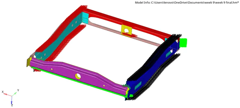
Model:
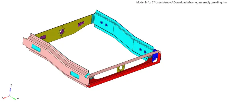
Parts which we have to connect:
1. Right_Rail_2 & Front_truss_1:- Seam-Quad(angled+capped+L)
2. Left_Rail_2 & Front_truss_1:- Quad elements
3. Front_truss_2, Front_truss_1 & Right_Rail_1:- Spot weld with 2 Layers and 5 mm Diameter
4. Front_truss_2, Front_truss_1 & Left_Rail_1:- Hexa (Adhesive)
5. Rear_truss_2 & Right_Rail_2:- Bolt Connector
6. Rear_truss_2 & Left_Rail_2:- Bolt Connector
7. Right_Rail_1 & Right_Rail_2:- Spot-weld with Rigid Elements
8. Left_Rail_1 & Left_Rail_2:- Spot-weld with Spring Elements
9. Rest all the component left Join them with suitable connectors.
What is 1D elements and connectors ?
1D elements: 1D elements are simple connection between two nodes in FE geometry.
Types of 1D connectors are
- RBE2: These are rigid links use to connects parts to distributeload with infinite stiffness.
- RBE3: Rigid links to distribute loads.
- BEAM/BAR are non rigid links also consider crossection and materialistic propery.
1D connector:
- This is also a geometric property which use to connect two parts of a model.
- Using spot and seam weld and also used to creat adhesive bolts and masses.
- They are medium to creat solver based independent and?or dependent connection between FE entities.
- It can be created from diffrent master connection files like (.xml .xcf .vip).
Types of connector:
Control module for diffrent types of connectors:

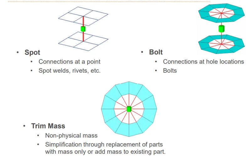
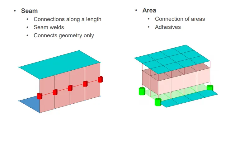
Realization of connectors: Creating the FE element representation of that particular connector.
- Rigid, Springs or custom configuraton such as ACMs and CWELDs etc.
State of connectors formation:
Unrealized: The initial status of connectors entity upon creation.
Realized: This is the state where the FE representation of that connector being successful.
Failed: This is the situation when the Fe representation of FE elements of connector being failed.It happens duen to the insufficient connecting entities and also due to low tolerance.
PROCEDURE:
- We will import the model first which is in .hm file format.
- After importing the model we will change it from by part to by components to see the clear view of different diffrent components on which we have to perform.
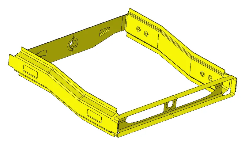
Fig:by part
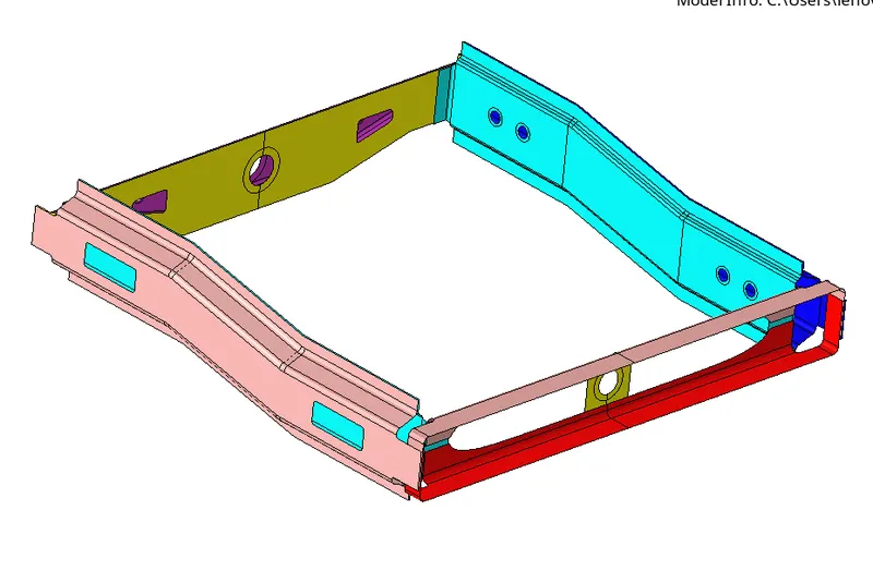
Fig: By component
- Now next step will be to mesh the component with quad mixed type element. After meshing we will proceed on connectors.
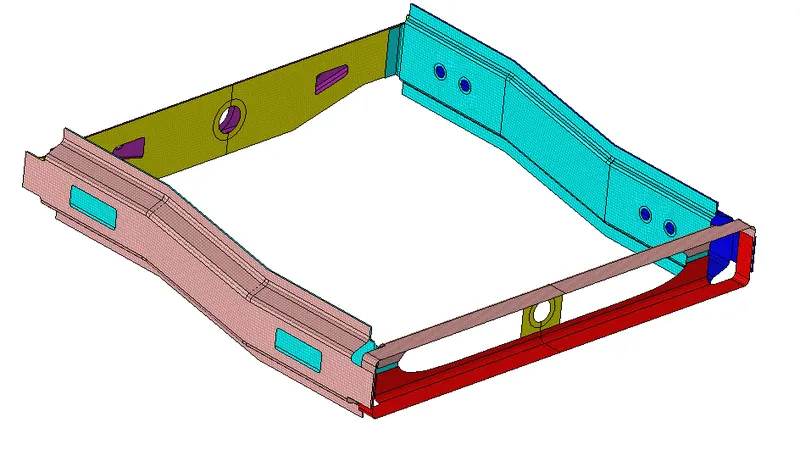
1. Right_Rail_2 & Front_truss_1:
- To perform this task first thing we have to do is we will hide all the other components except this so that we can focus this only and also there will be no chance of error in connector due to adjucent components.
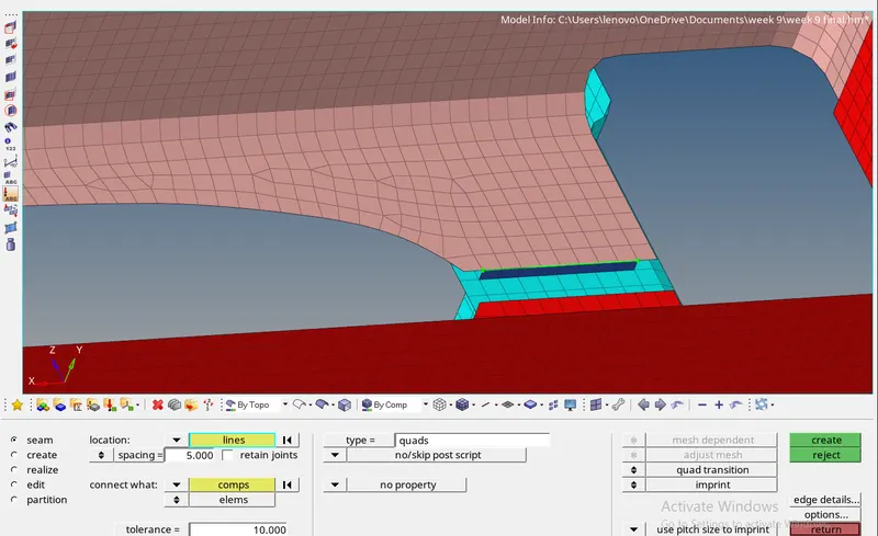
- As we know for these two components we have to perform seam quad (angled+capped+L).so we will go to 2D connectors pannel and select seam in the subpanel.
- After selecting the seam we will then select the node list cause as we know seam weld connectors is always on free edges.
- After selecting the node list we will go for selecting the components which we have to connect and the fill all the criteria for weld required like spacing(as 5 mm because target element size is 5 mm) ,tolerance( as 10 mm,it creat a range of 10mm radius to find the target component) and type of seam which is seam (angle+capped+L).
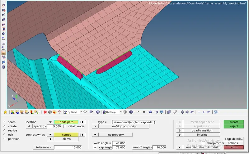
- We will go for 2D and select the connector option and simillarly we will choose seam weld cause here we have to make connection of seam quad.
- In seam weld will select the type of weld as Quad and for this we have to also select the node list on the free edges at common region as shown in below image.
- For this kind of weld we have to select the criteria as spacing of 5 mm and tolerance value.
3. Front_truss_2, Front_truss_1 & Right_Rail_1:-
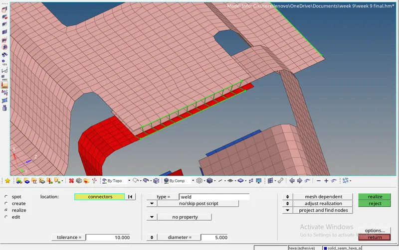
Here we will perform Spot weld with 2 Layers and 5 mm Diameter for this we will go to the 2D connector and select spot weld option in the sub panel.
- Here first we need to find the common surface of these two component the select the node list with node path to deploy the connection.
- And then choose the type of weld with putting the value of diameter as 5mm and tolerance value of 10mm.
- After this selelct the target components which have to be connected and then click on creat the connection.
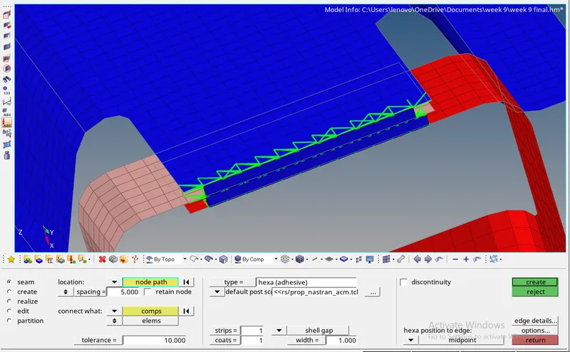
4. Front_truss_2, Front_truss_1 & Left_Rail_1:- To creat the hexa adhesive we have to go for subpanel of seam weld in 2D connector.
- For this connector again we need to select the nodelist by path and tick the retain nodes option to retain the position of nodes while creating the connection and making realization of connection.
- Then we will select the spacing value according to the target element size and set the tolerance value based on distance between two plates which we have to weld.
- After putting all the value then we have to select the components are going tobe connected and click on creat.
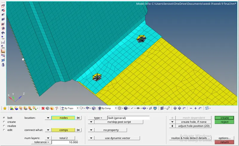
5. Rear_truss_2 & Right_Rail_2:- For Bolt Connector first we select the 2D panel and then will go for the bolt connector subpanel.
- In bolt connector first we have to find common surface(parallel) between these two components.
- Then will choose two nodes (if required two) on which we can creat hole for bolt connector.
- Then fill tolerance value and type of weld as general bolt and also select the option to creat holes if there is no hole.
- Now go for creat and then we can see it automatically created hole and rigid connection of bolt connector.
6. Rear_truss_2 & Left_Rail_2:- Bolt Connector
Simillar process as previous one, here is just different components are to be connected.
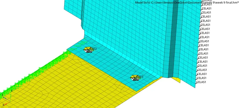
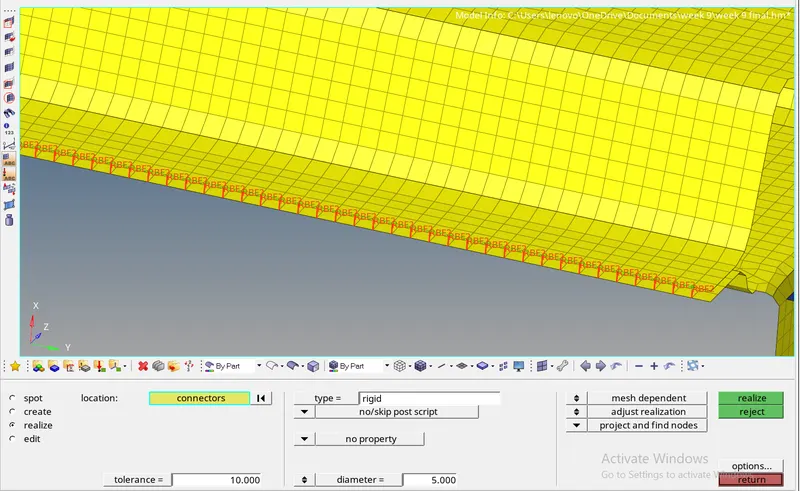
7. Right_Rail_1 & Right_Rail_2:- To creat Spot-weld with Rigid Elements we will go 2D connector and select spot weld subpanel.
- After opening the panel we will select the node list by path which we have to connect with parallel component.
- Then set the all value as spacing and tolerance.
- then select the type of weld we needed n spot weld which is rigid connection.
- then finally select both component which need to be connected and go for creat and realize.
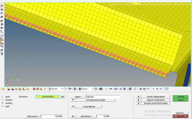
8. Left_Rail_1 & Left_Rail_2:- Spot-weld with Spring Elements
This one is also simillar to previous one,here is just to select the spring element instead of rigid elements in type of spot weld.
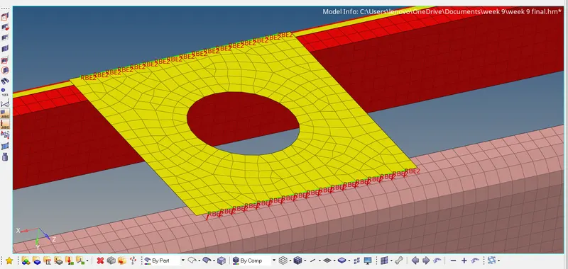
9. Rest all the component left Join them with suitable connectors:
RBE2:
Conclusion:
All the required connectionshould succesfully realized within the given geometry.Mesh flow should also be good and there is no quality issues to be found.