Assignment 1-2D Meshing Challenge
Aim-
- To perform preprocessing on all three model given according to qaulity criteria required for this challenge.
Objective-
- To import the model and perform geometrical cleanup.
- To extract midsurface for all the three components.
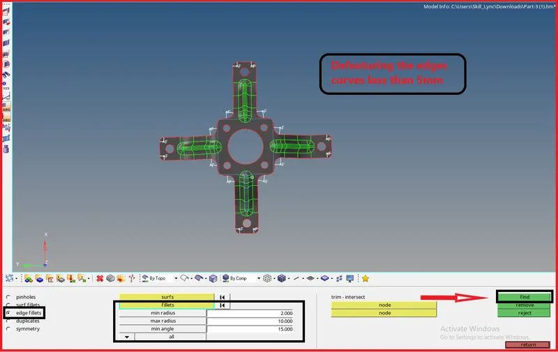
- To perform geometry cleanup on midsurface as well like defeature and holes less than 5 mm.
- To mesh the midsurface according to given quality criteria.
- To clear all the failing elements from quality.
- To assign the thickness to mesh to meet the component requirnment.
Procedure-
Satge-1
Import the model-
Model 1-
- Since we are importing the CAD file model in this challenge.
- So there are many type of file like IGES,STEP and parasolid we can use if we are importing a file into any CAD and CAE software.
But here in hypermesh we can use only three kind of file format:
- IGES(Initial Graphics Exchange Specification).
- STEP ( Standard for the Exchange of Product Model Data).
- SolidWorks.
Now these time most of the industries started working parasolid file formate also.
[Note: While importing the file into graphical user interface be sure that whether the file is .step or .iges file. Otherwise we will face difficulty during importing the model.]
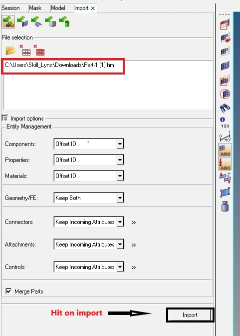
Tool we use to import in the way: File >> Import >> Import Model >> File type >> Open File.(As shown in below picture)
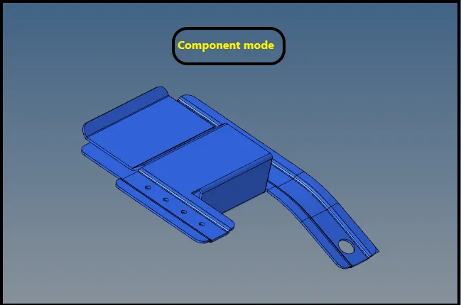
Imported Model-
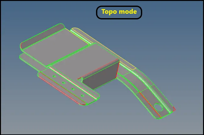
- Now we will check for the solid body after converting it into by topo model.
- After putting the model in by topo mode if model is having solid then it will show in green color.
- For deleting the solid Go to delete panel (F2) > select solid > select by displayed > Delete.
[Note- But here we can see that there is no solid inside the CAD body.]
Stage 2-
Geometry cleanup :
So after importing the model we will go for check the model for any geometrical glitch lik,
- Unnecessary surfaces.
- Free edges.
- Damaged geometry.
- Unwanted connection between surfaces.
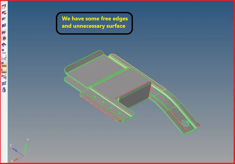
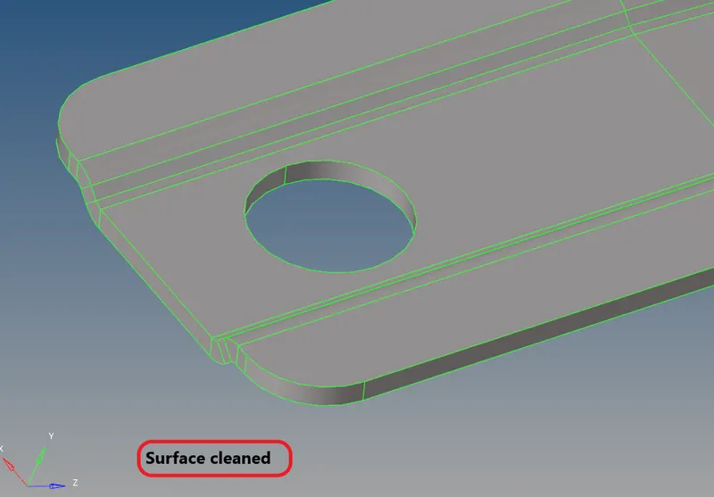
- Now we will try to get rid off these geometrical issues.
- For that f\red colour free edges we will do toggle,
Go to geometry > quick edit > Toggle > select the red lines > middle click
Note- It will ask about the value for toggle, set it as minimun as required to cover this toggle.
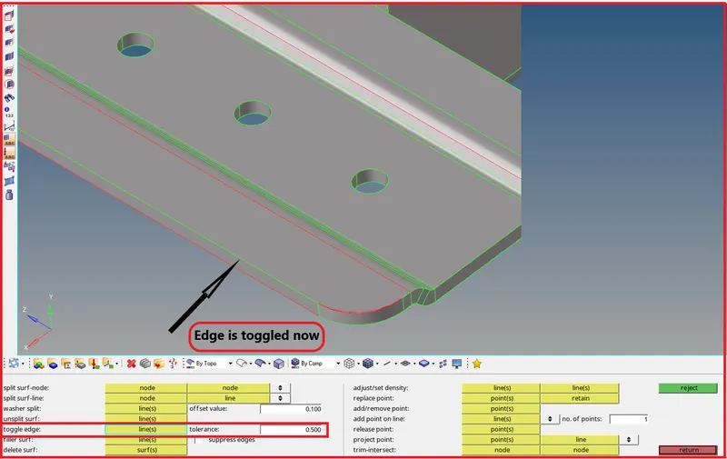
- Use fillet surface to complete continuous surface,
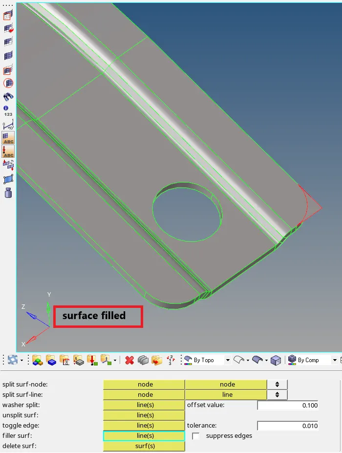
- Simmilarly we will do for all free edges.
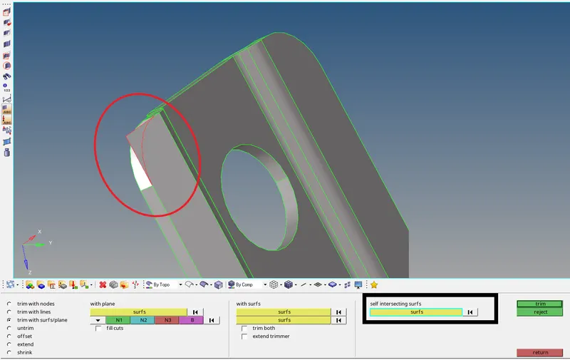
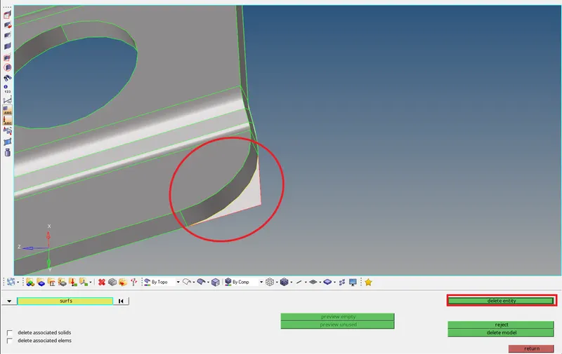
- After that we can see a unncessary surface here,
For that wew will trim the extra surface and delete as follows,
Go to Geo > surface edit > Trim with surface > select interselcting surface > middle click
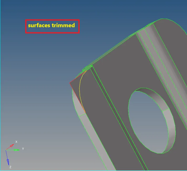
- Now delete the intersecting surfaces,
Stage-3
Midsurface extraction:
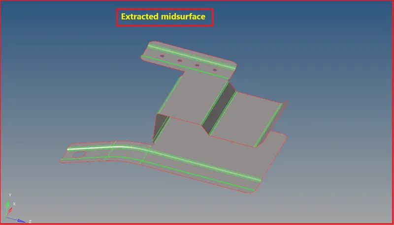
- As we can see here auto midsurface extraction is not practical so we will try to extract the midsurface manually.
- For that we have to check for the thickness for the components.
- Click F4 > distance between points > select points > Distance displayed now do half of that (1.4 unit).
- Now we will use automidsurface extraction since thickness is uniform.
- Go to geometry>midsurface > extraction type as skin midsurface > auto extract
Geometry cleanup on midsurface-
- As we can see there are most of the lines are closer to each other in respect to meshing.
- If we will perform meshing mehsing then elements might fail minimum size.
- So toggle those line in order to maintain feature.
Model is ready for mesh,
Stage-4
Meshing-
- Now we will start meshing the components part by part.
- And during meshing key points we need to take care about it.
Given Quality criteria for this model:
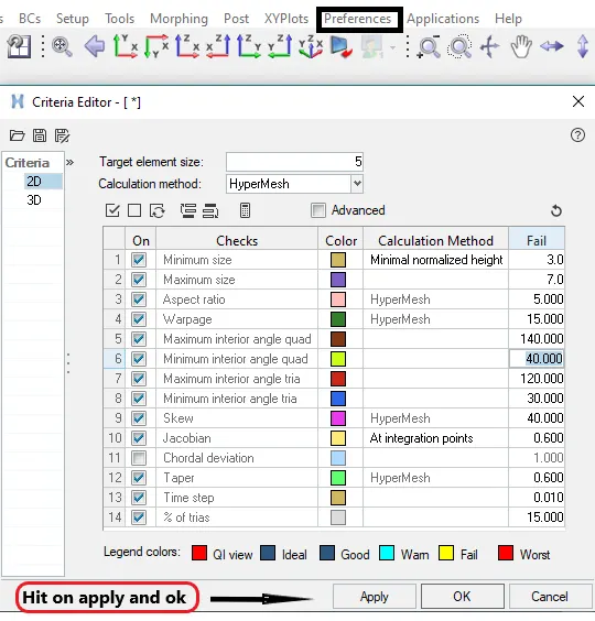
Target Element Length = 5 Units
S.N. Quality criteria
1 Min.Length shortest length of any given element 3.5
2 Max.Length largest length of any given element 7
- Criteria file setting
Key points for start meshing:
- Try to provide simplest kind of mesh elements in order to avoid failure.
- Provide smoother mesh in complex areas also because ananlysis we be based on our mesh.
- Start with coarse mesh and understand the modeling results.
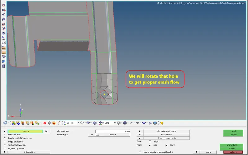
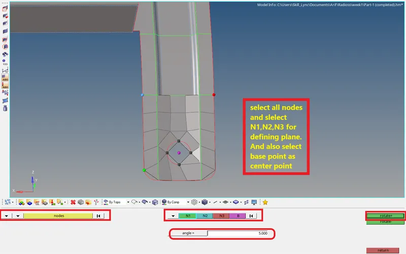
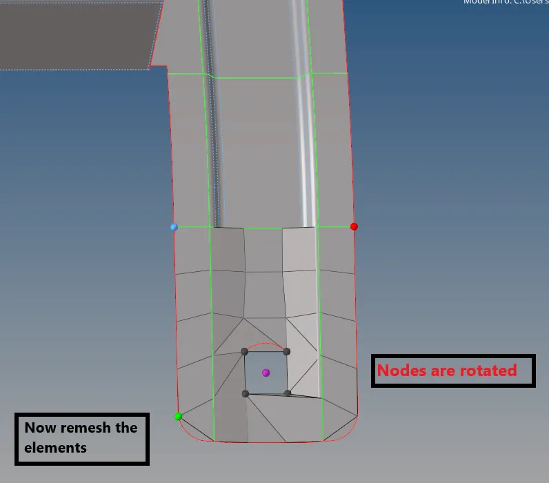
- so like this we will get proper mesh flow.
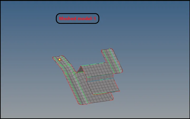
Final meshed model,
Stage-5
Assigning thickness-
- To assign the thickness create propert first
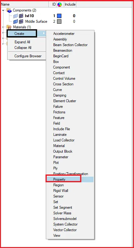
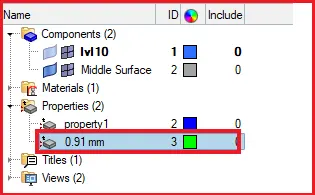
- Property is created now as 0.91mm.
- Now we will assign this property to the component.
Right click on component and select assign,
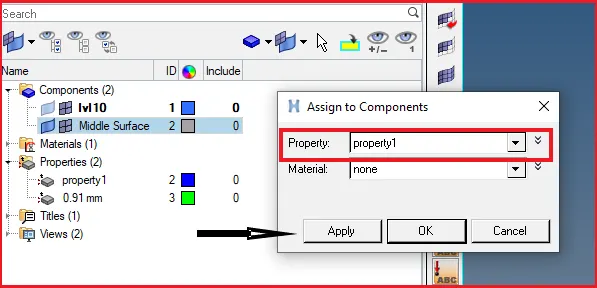
- Now after assigning the thickness,
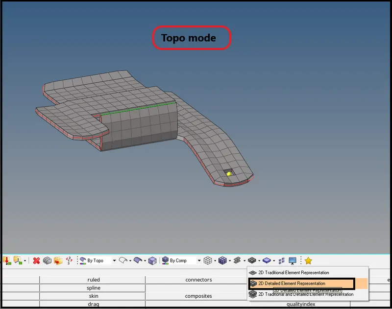
- Switch on to 2D detailed elements representation.
Final model after assigning thickness.
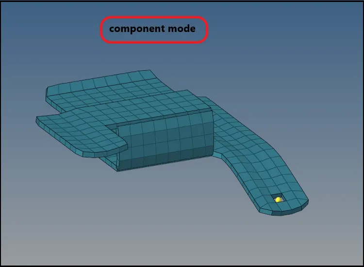
NOTE:
- Simmilary we will perform pre-processing for to other two components.
Model-2
Stage-1: Import
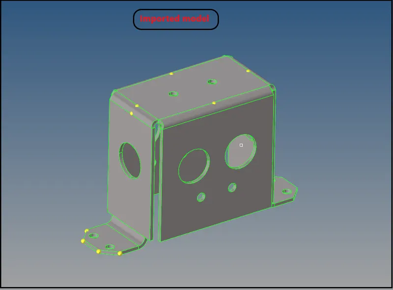
Stage-2:Midsurface extraction-
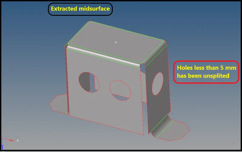
Stage-3:Geomtry cleanup
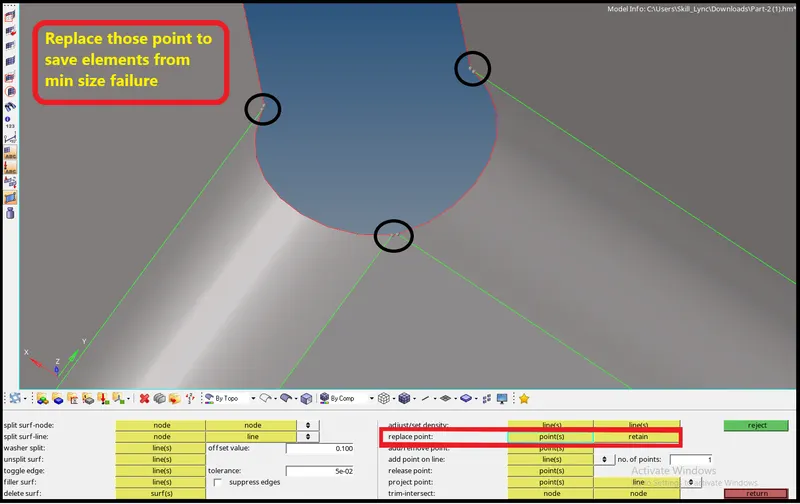
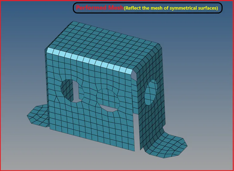
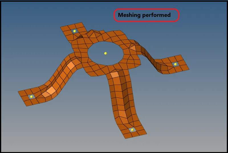
Stage-4:Mesing
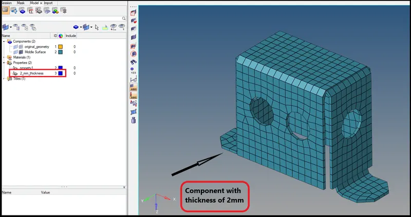
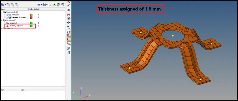
Stage-5: Assigning Thickness
Model-3
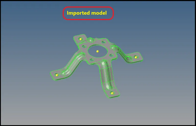
Stage-1: Model import
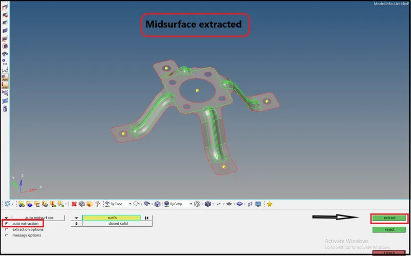
Stage-2: Midsurface extraction
Stage-3:Geometry cleanup for midsurface
Stage-4:Mesing
Stage-5:Assigning Thickness
Result-
- Midsurfaces extracted for all the 3 models.
- Geometry celanup performed for parent body and midsurface also.
- Meshed the midsurfaces of all three models.
- Thickness has benn assigned for all three models.