Project 2
PROJECT – 2 WIRING HARNESS USING CATIA V5 IN BACKDOOR
AIM:
To Route the Wiring harness which Application of all Packaging rules, Industry best practices studied in this course shall be demonstrated on Given car body and Prepare flatten view drawing in CATIA V5. Also Apply Protection coverings as required.
DESIGN METHODOLOGY:
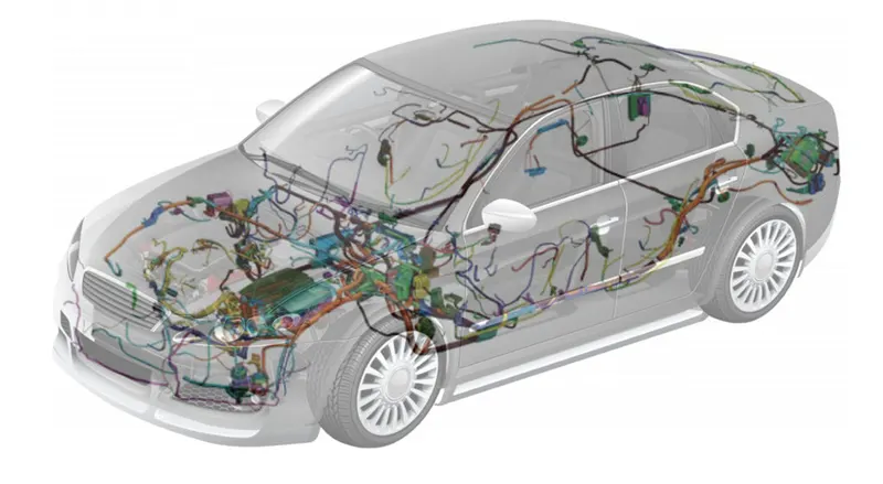
WIRING HARNESS:
Wiring harness is the combination of electrical and mechanical CAD to connect all the electrical parts in the automotive at the optimum level. It mainly consists of an electrical harness and the mechanical harness in the design. CATIA V5 electrical workbench is used as the CAD tool for routing the wires.
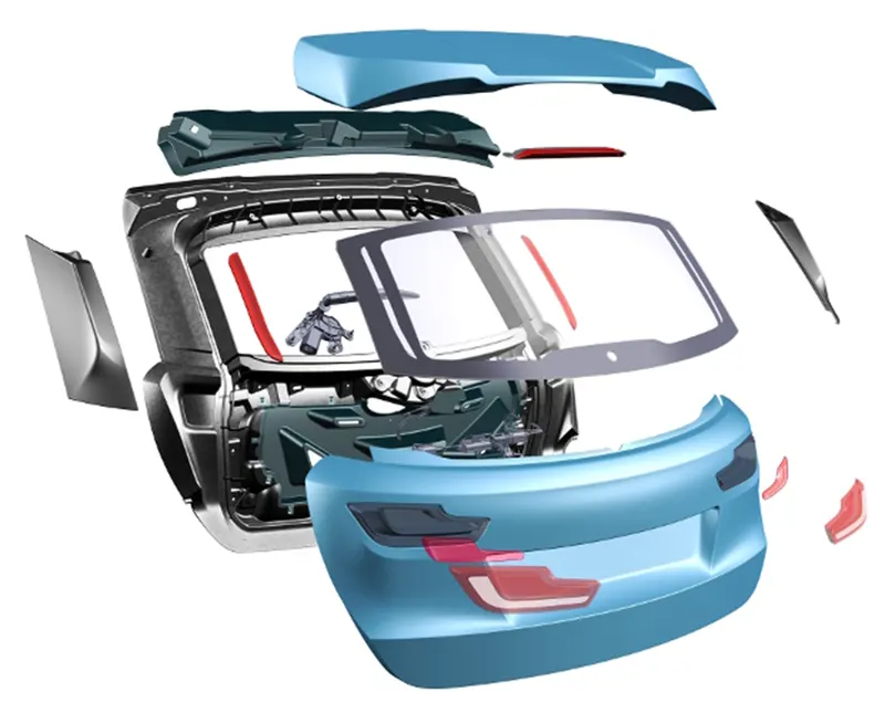
BACKDOOR:
Back Door is also referred as 'Hatch' or 'Tailgate' or 'Trunk-lid' or 'Boot-door'. It’s the rearmost part of the vehicle which gives access to the trunk and has mounts for tail lamps, hinges, wiper motor, gas stay etc. These doors can be operated manually or electric powered. In most of the luxury car’s door is electrically operated.

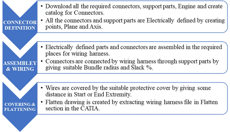
DESIGN OF WIRING HARNESS:
GIVEN CONNECTORS AND SUPPORT PARTS:
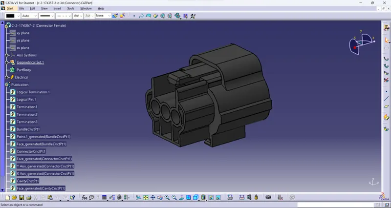
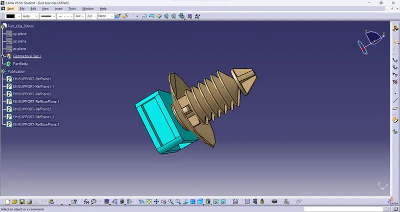
Following images are shows the parts for the wiring harness in the Backdoor which are electrically defined having Connector connection point, bundle connection point in the connectors and entry, exit way for the wires in support parts.
INTER CONNECTOR:
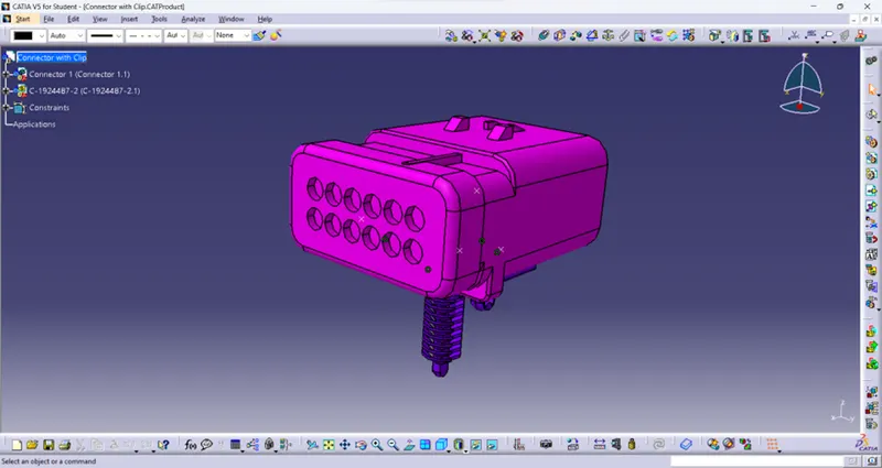
CONNECTOR 1:
FURR CLIP:
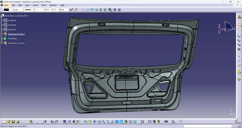
BACKDOOR PART:
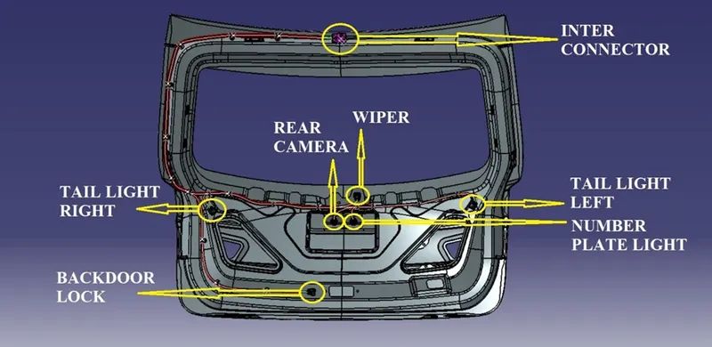
CONNECTORS WHERE REQUIRED:
- Inter connector (Main Connector)
- Tail light right
- Tail light left
- Number plate light
- Rear camera
- Wiper
- Backdoor lock
ASSEMBLE OF PARTS IN BACKDOOR:
After Electrically defined the required parts by using reference of Backdoor all the given connectors are assembled in their respective places by using parts assembly section. Then the support parts are placed in wherever required between the connectors for guiding the wiring harness Smoothly through it without any hurdles.
Below images represents the connectors and support parts are where assembled with backdoor and without backdoor.
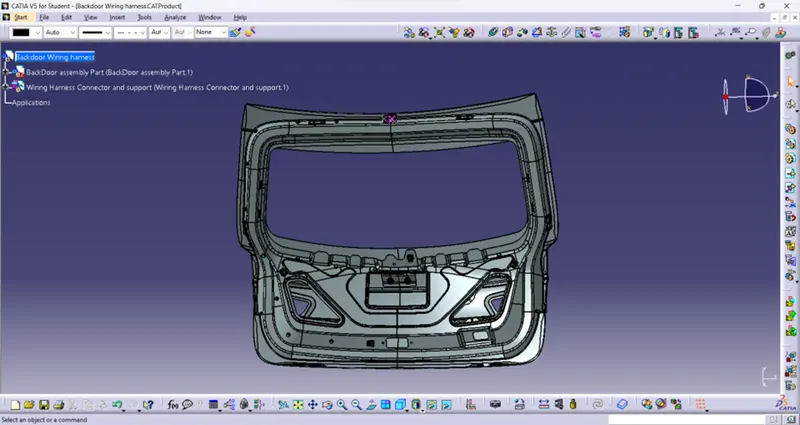
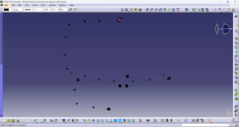
WIRING HARNESS;
CRITERIA AND PACKAGING CONDITIONS:
- Avoid the harness routing and clipping in the Blind zone of the Operator during harness assembly or in service.
- Wiring harness routing shall provide ease in manufacturing, accessibility, easy removal, and easy maintenance of attached equipment and wiring harness.
- Provide additional slack to the harness according to the surroundings and harness bending Ensure the routing meets the clearance requirements with different surrounding parts.
- Routing through small structural holes and openings shall be avoided, minimize chaffing and handling of the wiring harness during installation.
- Avoid harness routing near sharp edges, if not possible provide protection to the harness. The maximum distance between two clips on a straight branch is 200mm and minimum is 50mm.
- Min distance between clip and branching point to be 25 mm. Min distance between two branch breakouts should be 50 mm. The branch length should be more than 50 mm.
After all the assembles are done then connecting the connector by wire through Support parts and guiding channel which the bundle diameter are 10mm for main branch and 5mm for the individual connectors having one ways.
In the branch definition the bend radius should be minimum 1.4 and slack % is given wherever required for smooth wiring maintain the gap between wire and backdoor. Wiring harness in the backdoor with connectors by wires is shown below which is with backdoor and without backdoor.
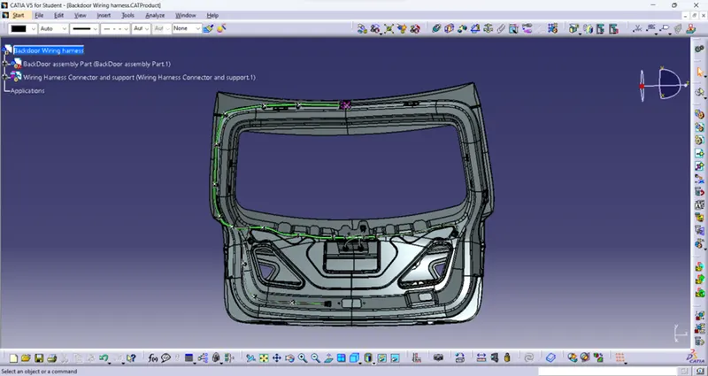
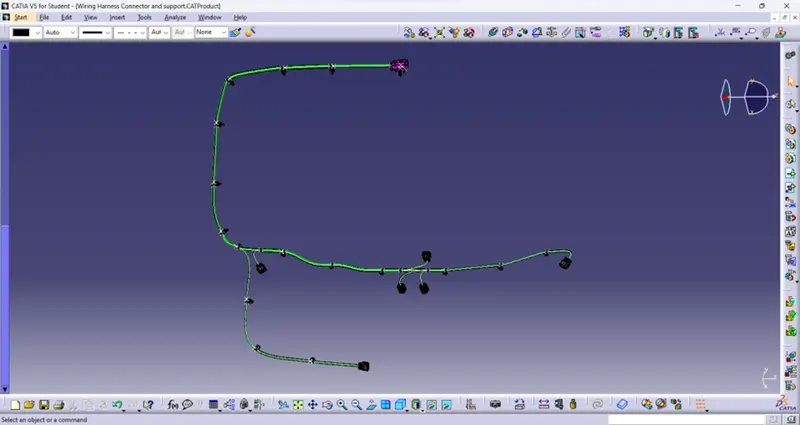
BUNDLE CONNECTION CHECKING:
After all the connection made, there is step to check the designed wiring harness is fully connected or not. Below images show the checking connection of bundle segment is fully connected or not.
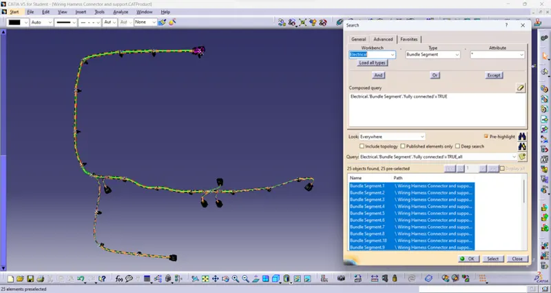
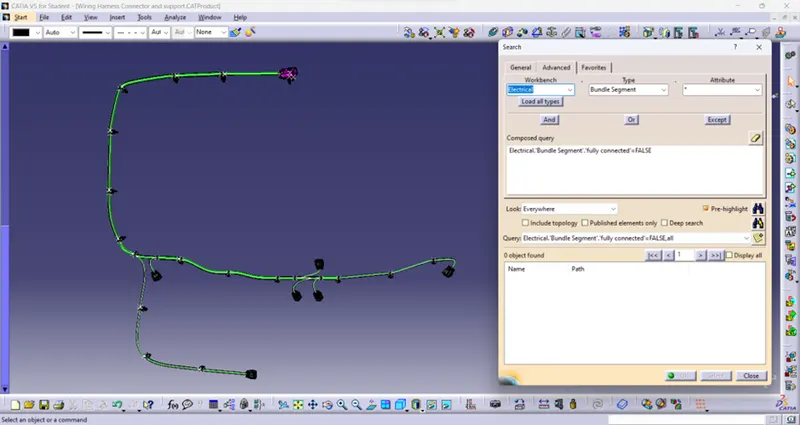
From the above images it shows that for TRUE condition it shows ALL CONNECTION and for FALSE condition it shows NONE connection. So, the designed wiring harness is FULLY CONNECTED.
PROTECTIVE COVERS:
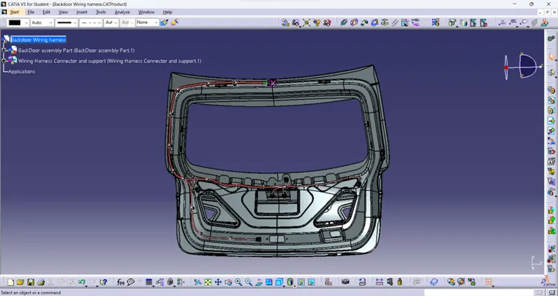
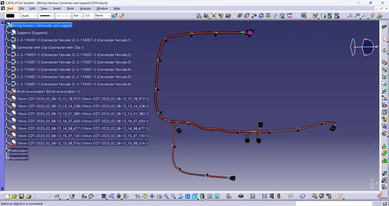
All the wires are Covered by the protective cover depends upon the bundle radius. Here the protective cover diameter should always higher than the bundle diameter. There is a gap provided between the covers and connector by giving value of minimum 25mm in Start or End Extremity.
Below image shows that the protective covers in the wiring harness with backdoor and without backdoor.
WIRING HARNESS FLATTENING:
It is done by open the flattening section in CATIA by given following parameters as shown below.
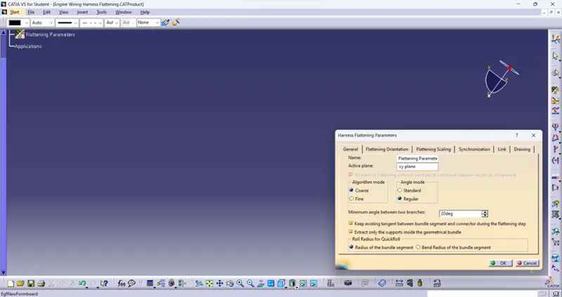
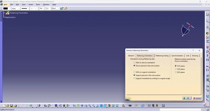
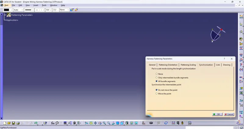
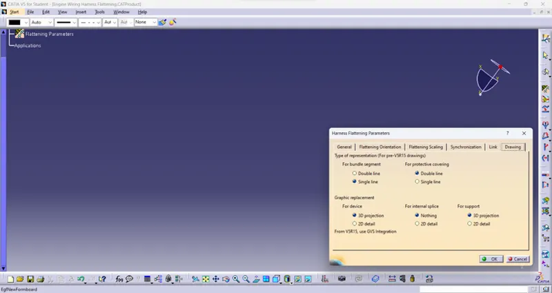
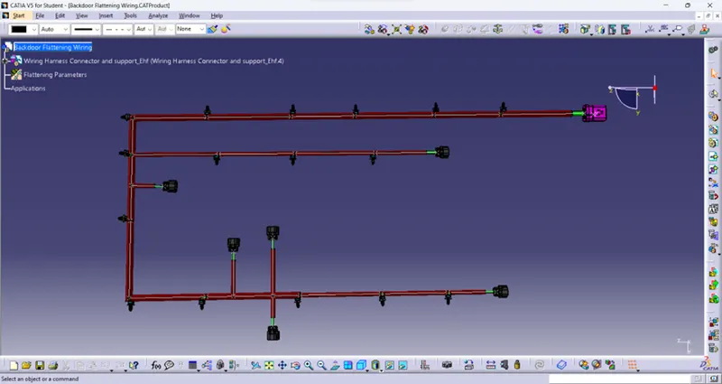
Then extract the bundle connection file into this file then done the flatten work by selecting the face of the interconnector and the extracted file. There is some intersection between them or lenghty which is not fit into the drawing sheet. By using Rotate, Scale and some other commands wiring branches and support parts are set in the proper place which to fit in the Flatten Drawing. The final flattening is shown below.
FLATTENING DRAWING:
Flattening drawing is made by open the drawing file in CATIA then made the borders and headings in the sheet. Then the flattening file is extract in the drawing sheet then fit into it. The resultant Flattening drawing with Bill of Material is shown below.
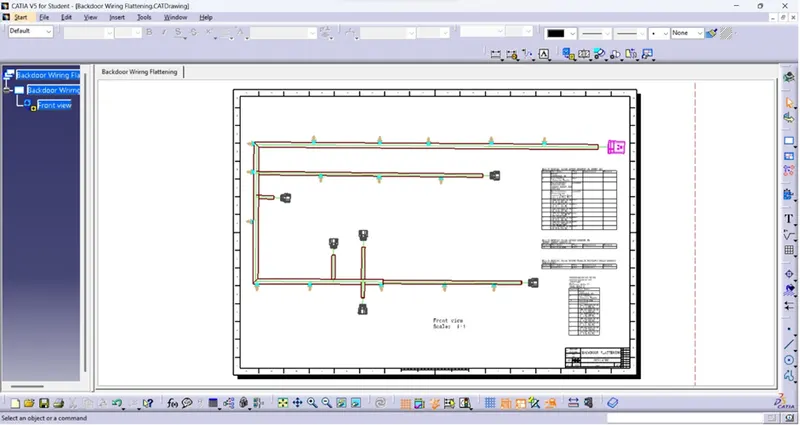
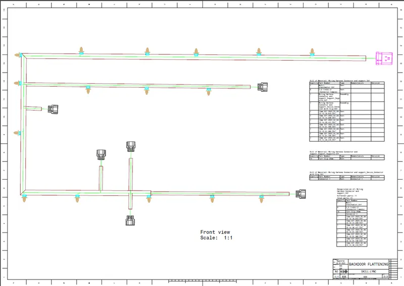
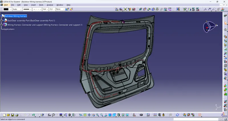
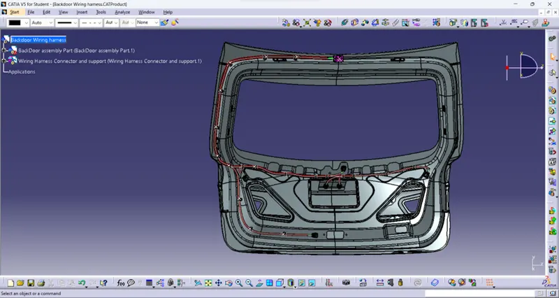
The resultant wiring harness in the backdoor is shown below.
Isometric view:
Front view:
Backdoor wiring harness connector definition:
CONCLUSION:
Thus, the wiring harness assembly is done in the backdoor by given connector with protective cover and also Flattening is made in it.