Fender Design - Wheel Arch Challenge
WHEEL ARCH GAP CALCULATION IN FENDER DESIGN
AIM:
To Calculate the Wheel Arch gap in fender design at required points and check whether the car passes the European standard.
FENDER:
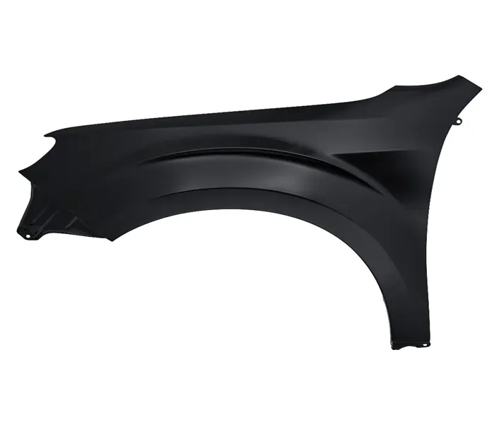
Fender is the part of an automobile, motorcycle or other vehicle body that frames a wheel (the fender underside). Its primary purpose is to prevent sand, mud, rocks, liquids, and other road spray from being thrown into the air by the rotating tire. Fenders are typically rigid and can be damaged by contact with the road surface.
WHEEL ARCH:
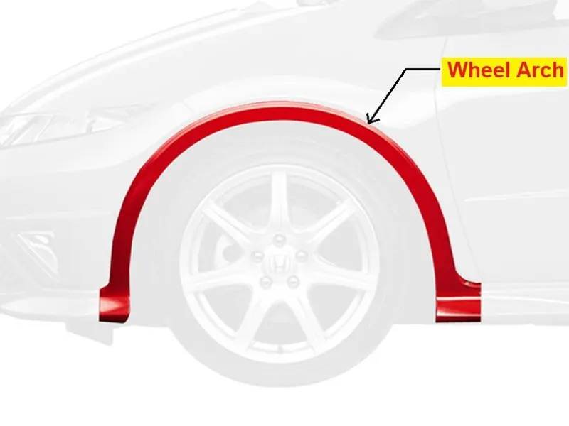
It is a curved part of the fender positioned right above the wheel. The wheel Arch is designed such that it protects both the pedestrian and car cabin from mud, water rocks and other road spray. Different countries have different wheel arch regulations in place, and the wheel arch design has to comply with them to be deemed usable in that country.
REGULATION OF WHEEL ARCH GAP:
FOR JAPAN STANDARD:
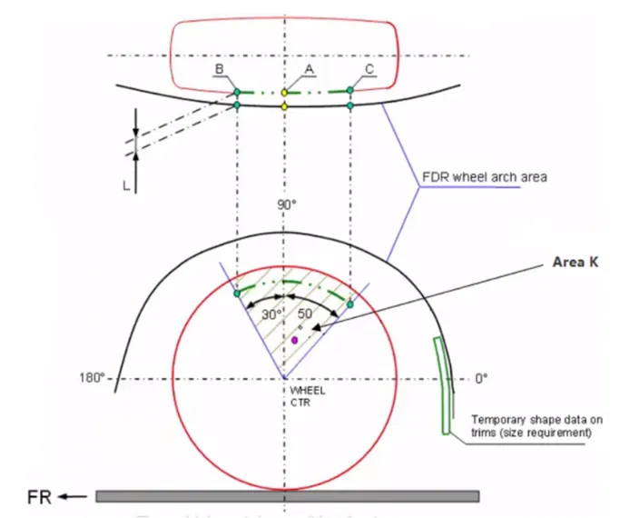
For Japan the gap is calculated in three points as centre A, with 300 left side B, with 500 right side C. The gap L is always above 5mm.
FOR AMERICAN STANDARD:
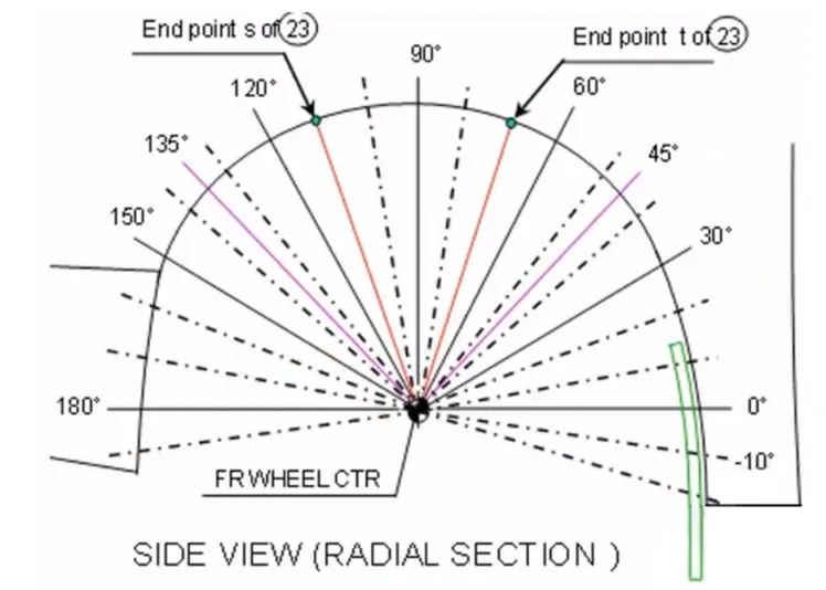
For American standard the gap is calculated in several points which is projected in several angle. Here the gap is always 5mm.
FOR EUROPE STANDARD:
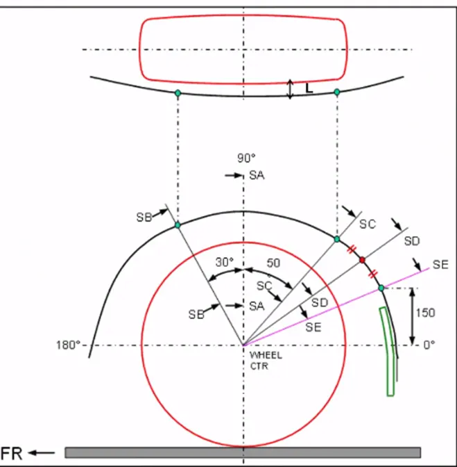
For Europe standard the gap is calculated in 5 points the centre line SA, with 300 left side SB, with 500 right side SC, intersection point which the horizontal line offset by 150mm intersect at fender arc SE and the point of derived line of SC and SE intersect at fender arc SD. Here the gap is always above 10mm.
CALCULATION OF WHEEL ARCH GAP:
Initially the datum plane is created on the outermost surface of the wheel for sketch the intersection point.
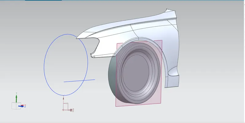
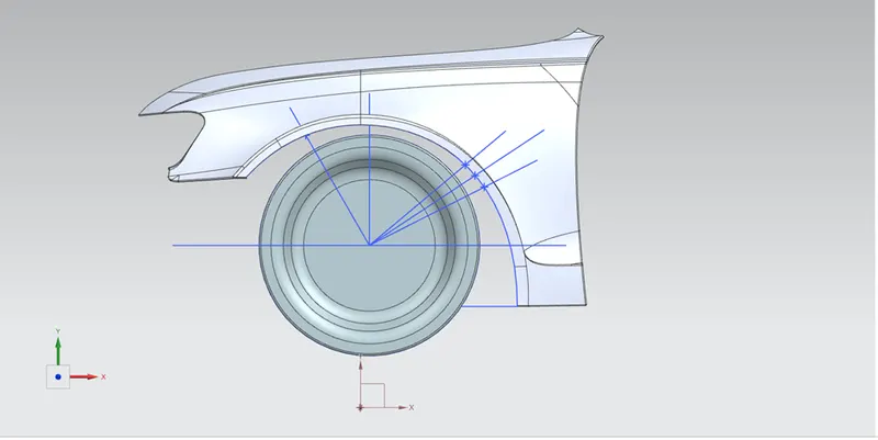
Then create the sketch on the created plane. In sketch, the horizontal line is drawn which midpoint of line is coincidence with the centre point of the wheel. Then the vertical line is drawn from midpoint. Two lines drawn left side at 300 and right side at 500.
Horizontal line is offset at 150mm upward direction and create the intersection point of this line to fender arc, then line is drawn from this point to midpoint. Derived line is drawn by third and fourth line to create fifth line.
5 intersection point is created by those above 5 lines with the fender arc.
By projected curve command those 5 intersection points are projected on the surface of the fender which shown below.
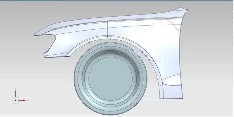
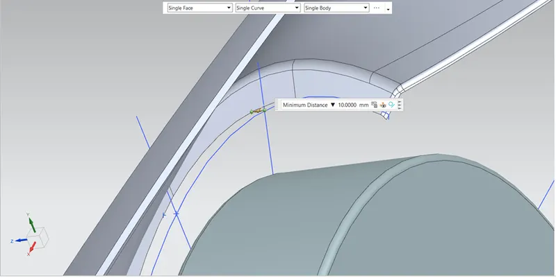
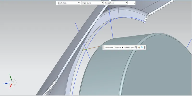
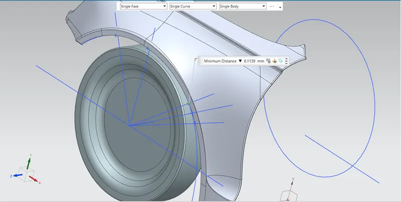
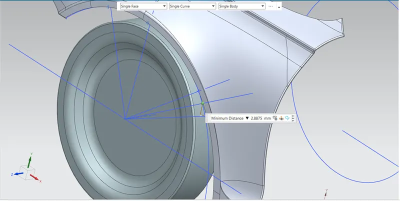
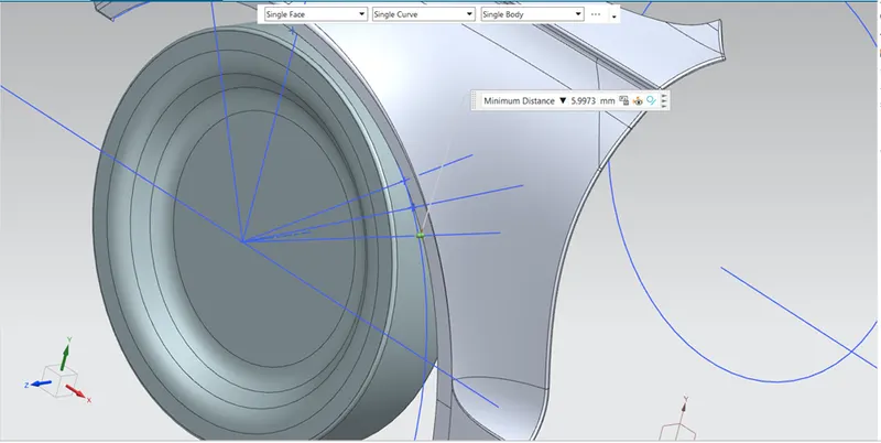
Those points are SA, SB, SC, SD, SE. below images are shown the gap of those points.
For SA:
For SB:
For SC:
For SD:
For SE:
Calculation Table:
| S. No | Section | Gap value | Result |
| 1 | SA | 10 mm | PASS |
| 2 | SB | 9.9490 mm | FAIL |
| 3 | SC | 0.1139 mm | FAIL |
| 4 | SD | 2.8875 mm | FAIL |
| 5 | SE | 5.9973 mm | FAIL |
From above table value in green is positive and value in red are negative.
CONCLUSION:
The gap value of wheel arch is one is Pass have 10mm and other four values are below 10mm and that have negative value also. For design consideration even one value is minimum than the desired standard value (10mm) the part is fail. Here four values are not in desired standard value. So, the given fender part is FAILED DESIGN. Thus, the calculation of fender wheel arch gap is done and result is checked.