Week 8 - Challenge 6 - Core & Cavity Design
SWITCH BEZEL CORE AND CAVITY BLOCKS CHALLENGE - 6
OBJECTIVE:
To create the Core and Cavity component for the Switch Bezel Component.
DESIGN METHODOLOOGY/APPROACH:
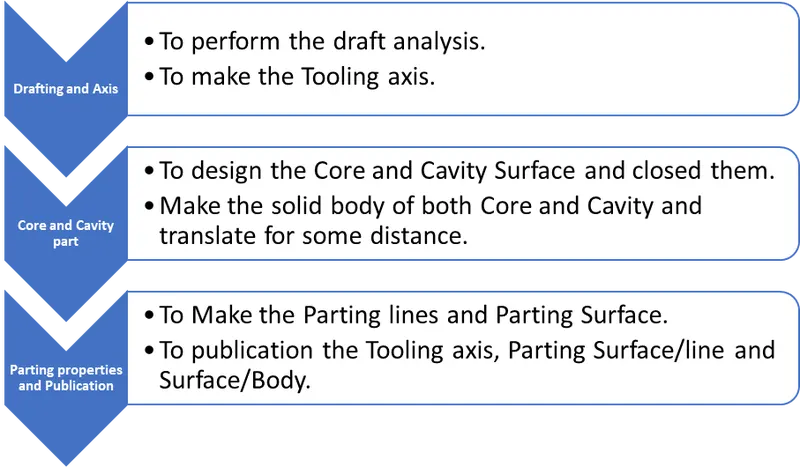
Draft Analysis:
Draft analysis is the analysis to examine whether the designed part is exit from the mould smoothly or not. Generally, 3 degrees from the Class A surface to be drafted. In the below diagram draft analysis is performed by given Class A surface.
Draft Analysis of Class A:
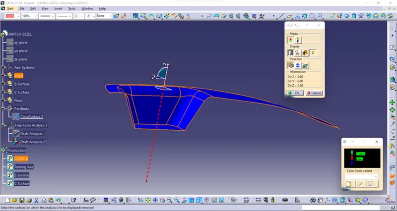
Draft analysis of Switch bezel compenent:
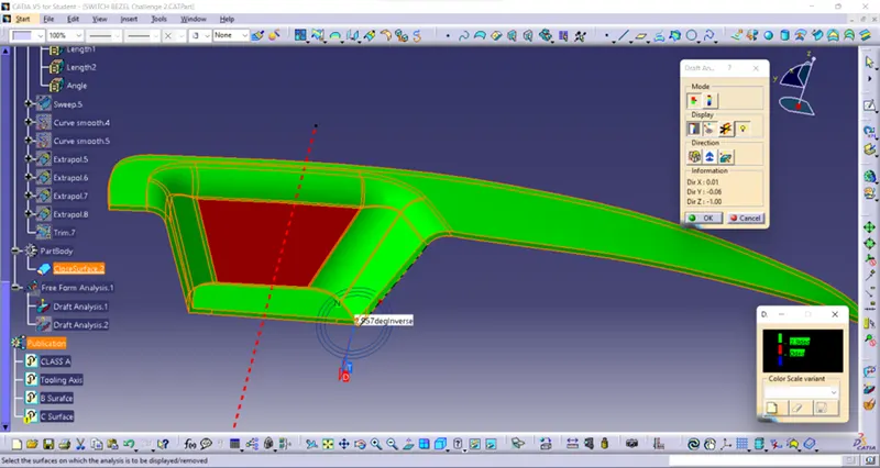
Mould:
A Solid body have a carved shape of a component which is made by mass production by inserting their raw materials into it by applying pressure with tightly closed is known as Mould. Generally, mould have 2 sections they are Core and Cavity. The core is the male part which forms the internal shape of moulding. The cavity is the female part which forms external shape of moulding.
Tooling axis:
Axis which drafts the part from certain angle is called tooling axis. Initially the part is checked in all direction for tooling axis, the suitable direction for tooling to be selected considering reduce the mould cost. In this part considering all axis Y axis is best for tooling. But there is Axis system is insert in the base surface with point create the line which is parallel to Y axis, then using of intersect command intersect the given class A surface draw the line from centre with angle and made the bisecting line by created two lines. Finally, the tooling axis line by using bisecting line and points.
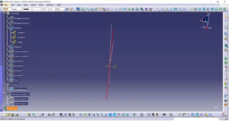
The drawn tooling axis is shown below.
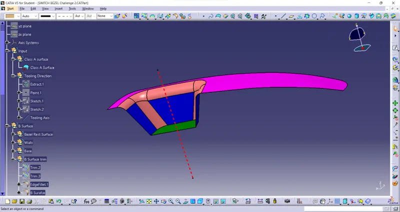
Making of Core, Cavity, Parting line/Surfaces:
Core:
Initially unhide the B and closed surface and drawn the rectangle as shown in figure.
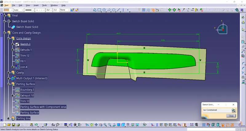
And extrude it both direction which covers the whole closed surface.
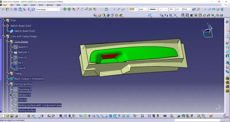
Then trimmed it with B surface and closed the open surface finally by using Add command add them.
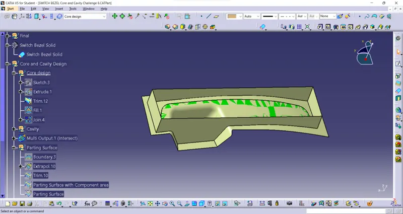
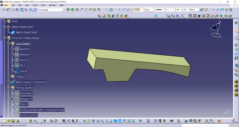
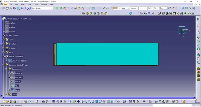
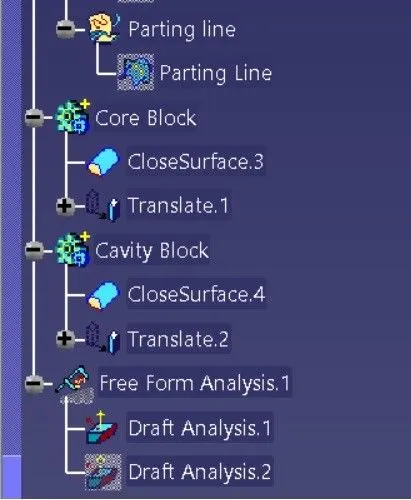
By insert body as Core Block define it in part design made as Closed surface and turn into solid body as shown as below.
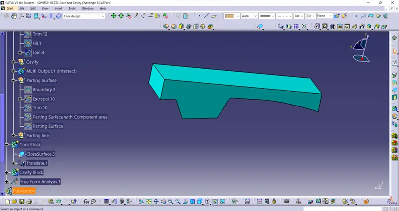
Cavity:
As same as Core initially the same sketch extruded as same value and trimmed by B surface but keeping down side and trimmed upside. Then closed it and add it.
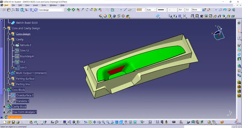
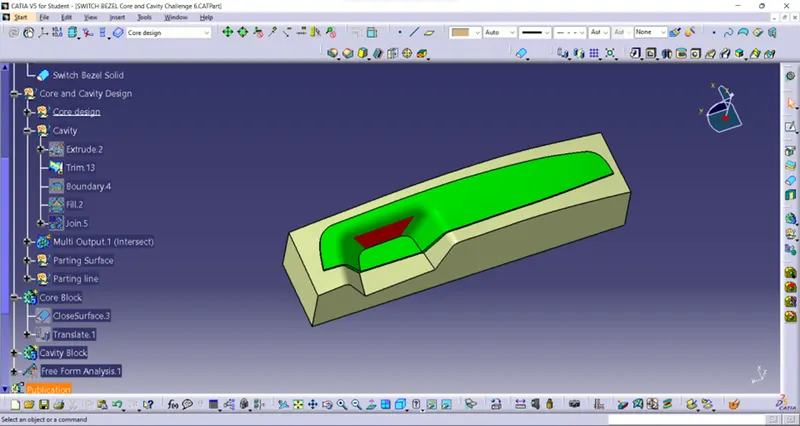
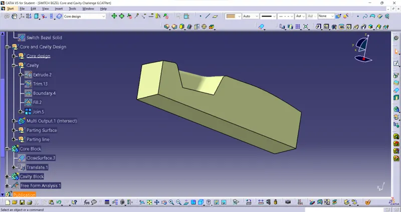
By insert body as Cavity Block define it in part design made as Closed surface and turn into solid body as shown as below.
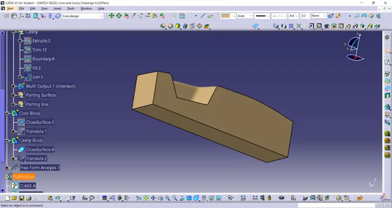
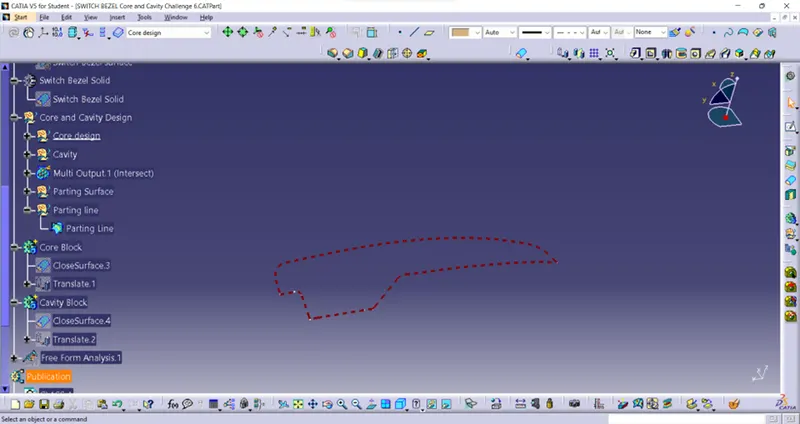
Parting line:
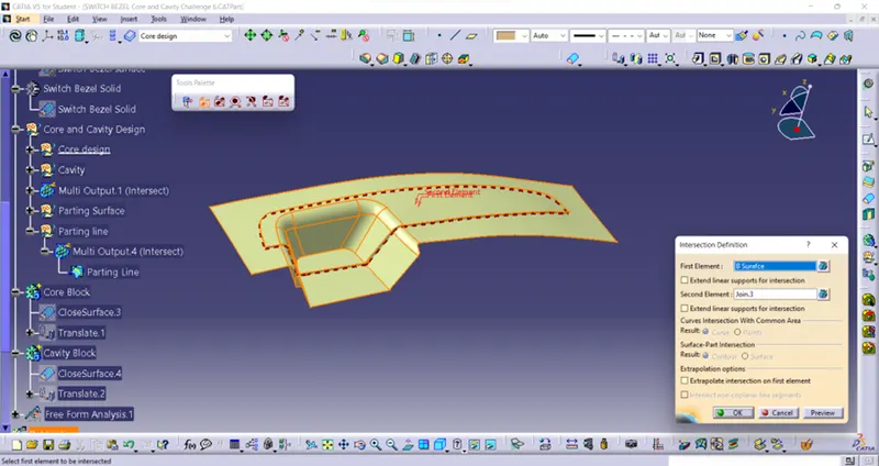
The parting line indicates the direction of the line of draw for the mould, or the point where you can separate the two halves of the mood to release the part without damage.
Parting line is made by intersecting the B surface and Combine of A and c surface which is shown in below.
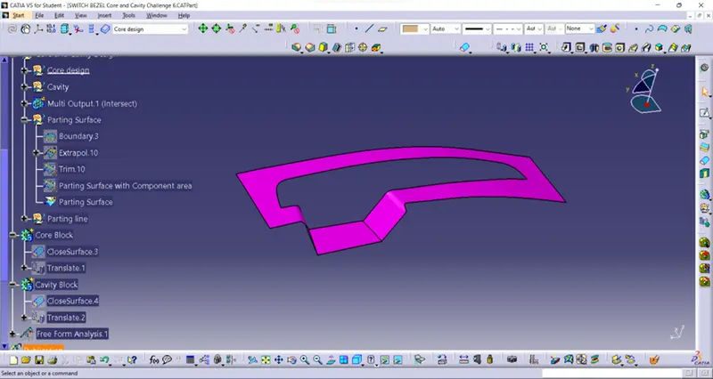
Parting Surface:
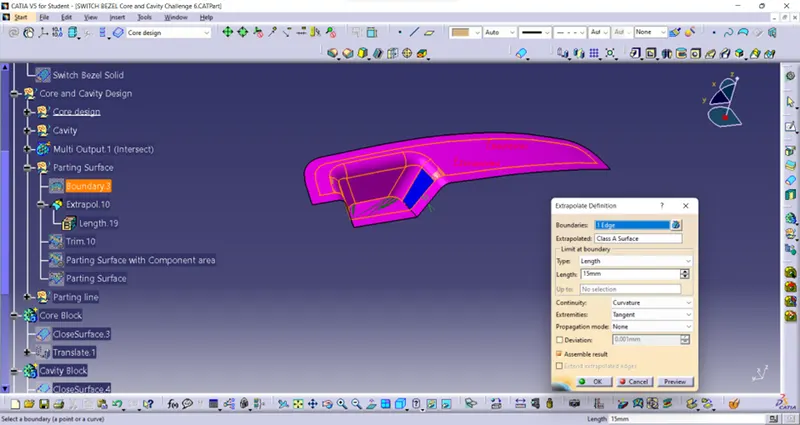
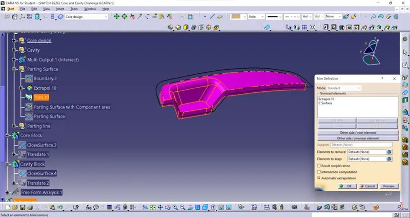
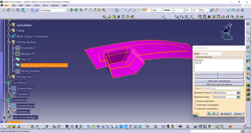
The parting surface of a mould are those surfaces of both mould plates adjacent to the impressions which butt together to form a seal and prevent the loss of plastic material from the impression.
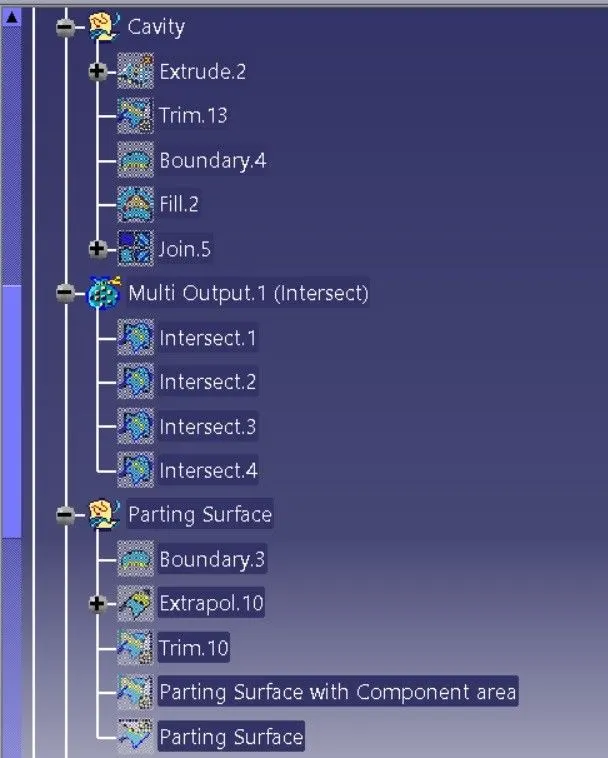
Class A surface is extrapolated into 15mm distance. Then trimmed it with C Surface and trimmed with B surface. Finally, it is split by parting line the result surface is Parting surface.
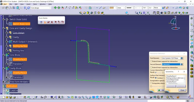
Intersecting the surfaces:
Some surfaces are intersecting for examine whether the designed mould is correct or not and also define the areas of core, Cavity and parting areas. Here core, Cavity, the final part blocks and parting surfaces are intersecting which is shown in image.
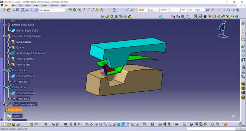
Core and Cavity translating:
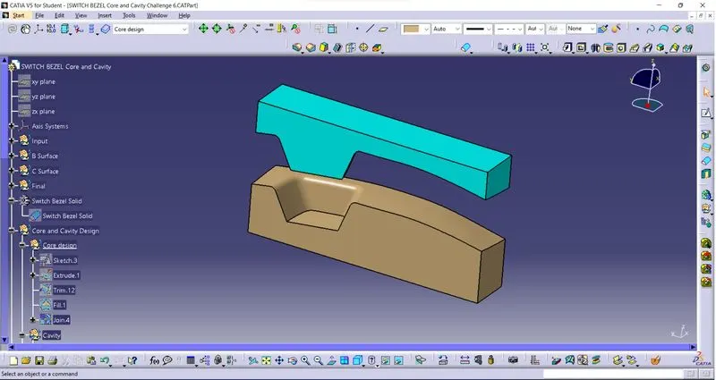
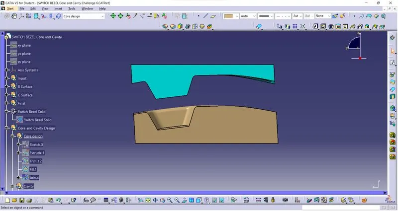
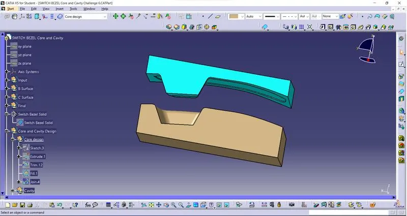
Then the Core and Cavity Blocks are translated into 50mm distance as shown below.
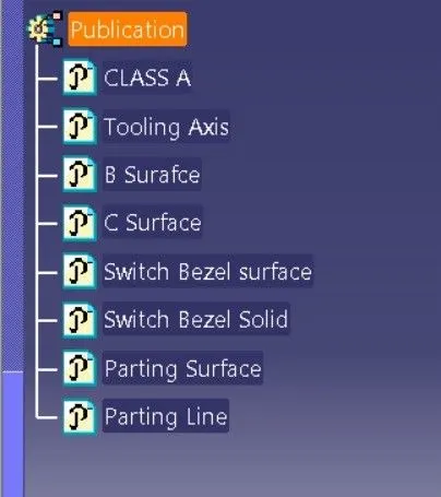
Finally published the Tooling axis, Switch bezel surface/body and Parting surface/line.
Conclusion:
By using above methods Core/Cavity blocks and parting line/Surfaces of Switch Bezel are made.
Expanded tree structure 1:
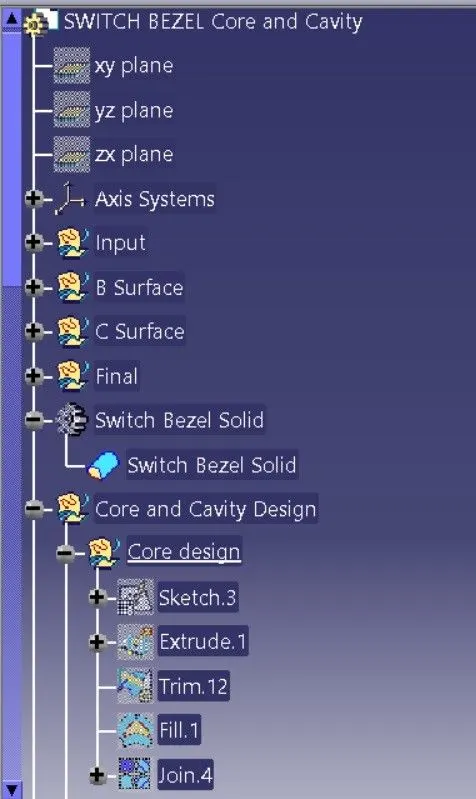
Expanded tree structure 2:
Expanded tree structure 3:
Expanded tree structure 4:
Isometric view:
Front view:
Side view:
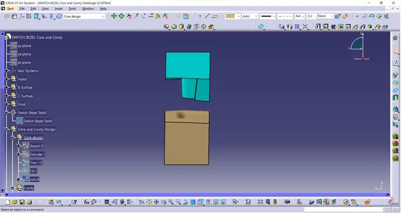
Top view: