Roof Design
ROOF DESIGN
AIM:
To create the Roof Design and an ASSEMBLY by developing the essential flanges for the outer roof,creating the reinforcements and also perform Draft analysis and calculations to determine the strength of the roof.
DESIGN APPROACH:
INTRODUCTION:
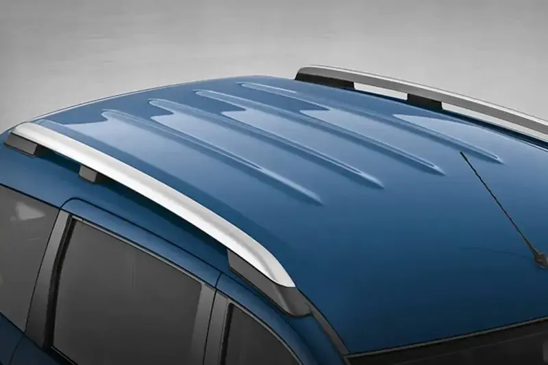
An automobile roof or car top is the portion of an automobile that sits above the passenger compartment, protecting the vehicle occupants from sun, wind, rain, and other external elements. Roof is the structure above the wind shield glass having the reinforcements to provide the strength to the overall structure.
ROOF SAFETY AND TEST:
Passenger safety is also a very important parameter in front of OEMs. For this reason, strength is a very important criteria for designing a vehicle roof. The strength of the roof structure to occupant the protection in real world crashes, requiring the maximum moving distance of the roof structure should be less than 127mm when the induced load is 1.5 times the vehicle weight.
For the test, the passenger car shall be rigidly placed or positioned on horizontal surface with the doors locked and the window closed. This test can be conducted on either side of the roof structure, the front left or front right side but not on both sides in one single test and still meet the requirements of the test.
The rigid plate shall not move faster than 0.5 inches/second and the force applied on the plate shall not exceed the lesser of 1.5 times the unloaded vehicle weight (UVW) expressed in kilograms multiplied by 9.8 or 5000lbs Also, the direction of the forces shall be downward and perpendicular to the lower surface of the rigid plate and such that moves in a straight line without rotation.
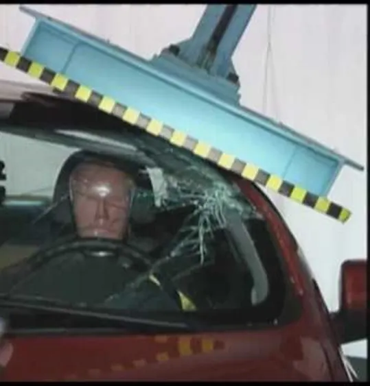
The duration of the test shall not exceed 120 seconds. The longitudinal axis of the plate is pitched forward at a 5° angle as viewed from the side of the passenger car. Roof crush test image is shown below.
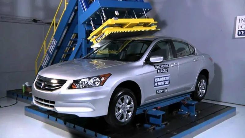
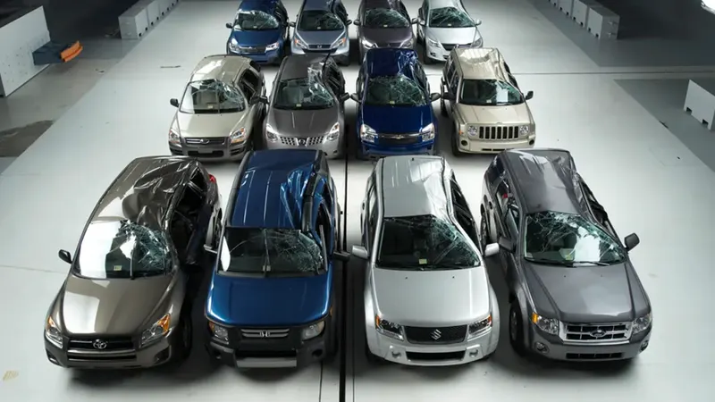
So, there is some flanges such as Roof Rails and Reinforcement are connected to the roof to give strength to it.
PARTS OF ROOF:
- Outer Roof
- Front Roof Rail
- Rear Roof Rail
- Centre Roof Rail
- Bow Roof Rails.
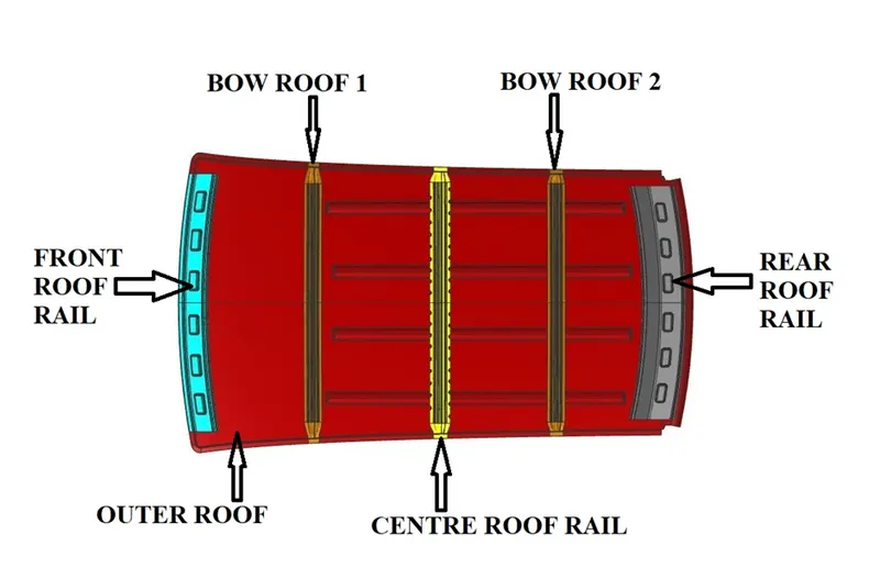
DESIGN OF ROOF PARTS:
OUTER ROOF:
Outer roof is top surface of the roof which is visible having some flanges in sides for connect to the Rail roofs and door panels. Here some roofs have sun roofs.
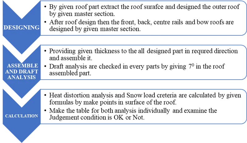
Initially one side of the outer surface is extract for outer roof design. By considering Master section mentioned in green line the outer roof is designed by Offset surface, offset curve, Law extension, trim sheet as per the given dimension.
DITCH AREA:
The ditch area is the extended portion of the main roof which is concealed by the other BIW components followed by the other aesthetic surface. It also serves the joining purpose for the reinforcement which is joined using the spot welding. Visibility, Clearance for windshield and back door mountings are some of the factors needed to be considered while designing the ditch area.
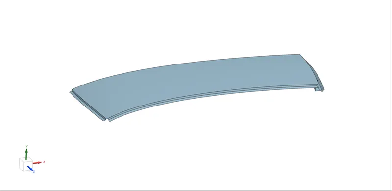
At the corner the curves are created by bridge curve and surface is created by through mesh curve. Then the embosses are created in the top of the surface and finally the edges are blended. Resultant surface is mirrored by plane to form full surface. Final surface of outer roof is shown below.
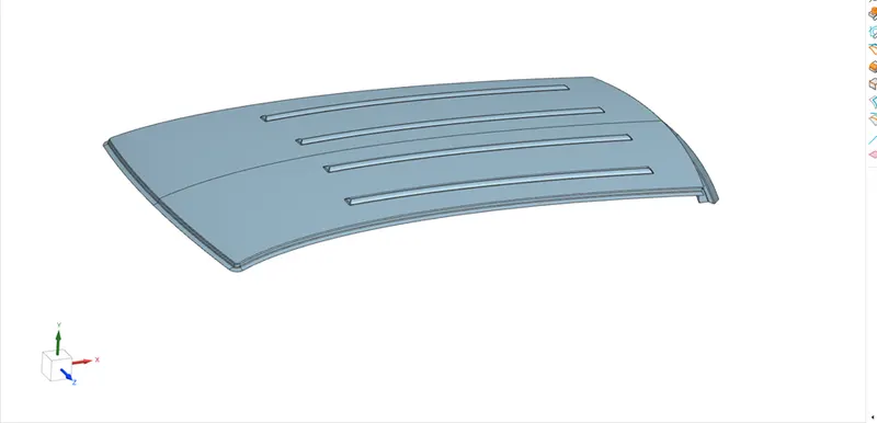
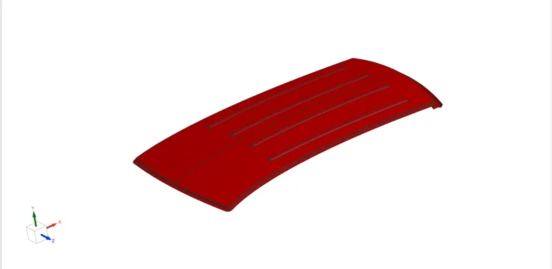
Surface is thickened by 0.75mm to design the outer roof part.
FRONT ROOF RAIL:
It is located in the front side of roof which has some height clearance to the passenger which spot weld in the end flanges also have embosses to provide strength.
As per the same procedure of outer roof design by extract the surface of roof Front roof rail surface is designed by given master section as per the dimension.
MASTER SECTION:
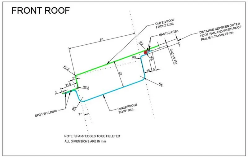
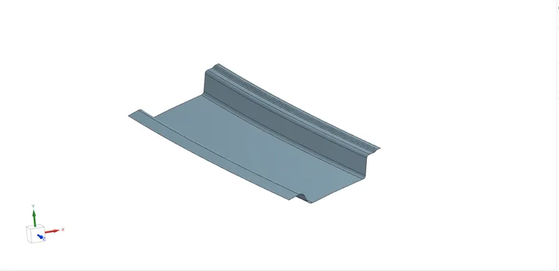
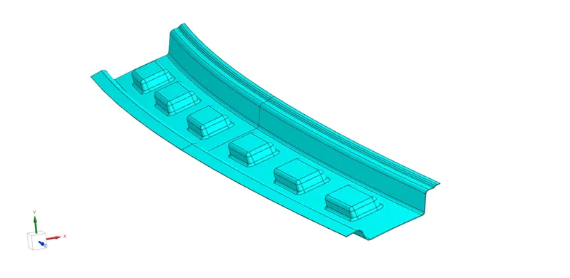
Then embosses are created on the surface for aesthetic purpose then the surface is mirrored. The final front roof rail surface is shown below.
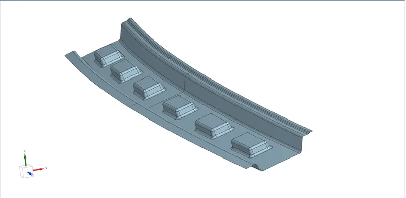
Finally, the surface is thickened by 0.75 mm for the Front roof rail part.
REAR ROOF RAIL:
Rear roof rail is located in rear side of the roof which is also connected to the door panel by spot welding in the end flanges.
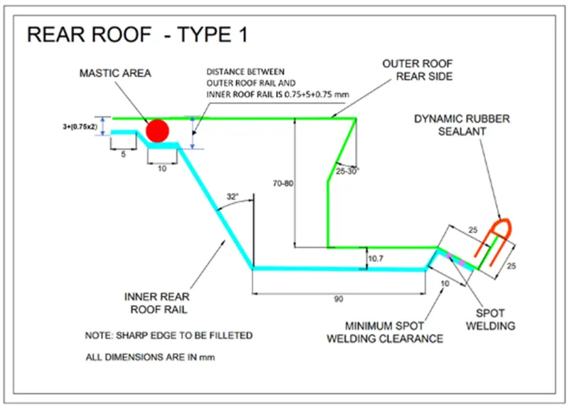
For design the surface of rear roof rail the step above done are repeated here by considering Master section as per the dimension in it.
MASTER SECTION:
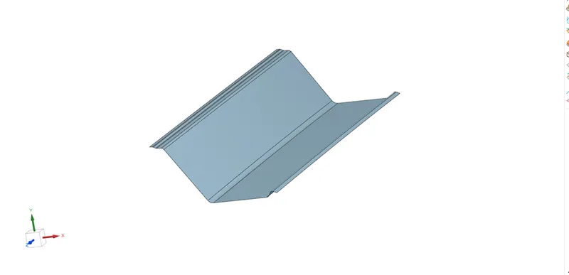
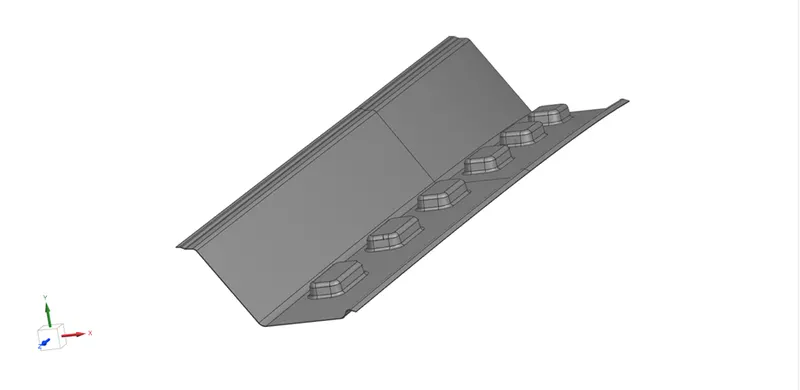
Embosses are created on the surface and mirrored by plane, the final surface of rear roof rail surface is shown below.
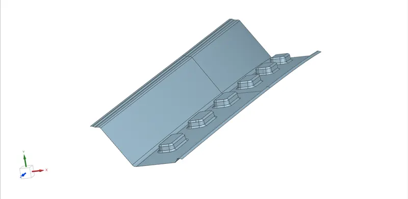
The final surface is thickened by 0.75mm to form Rear roof rail part.
CENTRE ROOF RAIL:
It is placed in centre which is above 50% length from front side which is connected by spot welding in end flanges and the remaining portion are joint by Mastic section. It is differed by the roof type which the sun roof is present or not.
By considering master section centre roof surface is designed by extract the surface of roof intersect the surface by plane on 55% length in the surface. By intersecting line, the commands which is used in above steps are repeated as per the dimension.
MASTER SECTION:
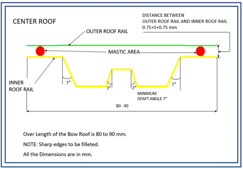
For mastic points the surface are trimmed by project the curve on it which is sketched based on a plane in the surface. By extract side flanges two planes are created on it between the length of centre roof for intersecting and trimmed it. Then the surface is offset by 1.5mm, by bridge curve command the curve is created and the surface is made between them.
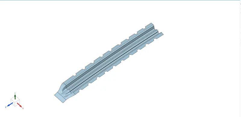
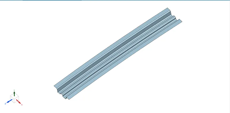
Then the surface is mirrored and the final surface of centre roof rail is shown below.
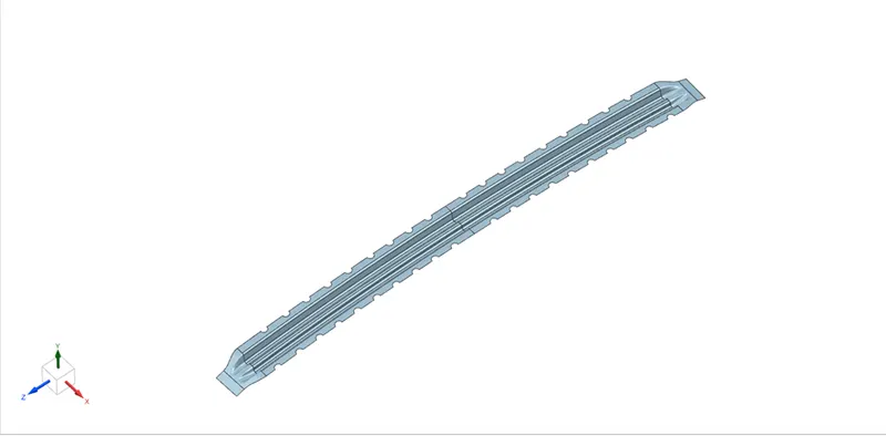
For making centre roof rail part the surface is thickened by 0.75mm.
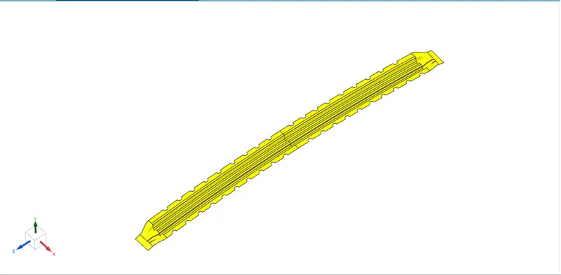
BOW ROOFS:
Bow roofs are placed in roof by provide some gaps in two side from centre rail roof it has also same type of connection to the centre roof rail.
MASTER SECTION:
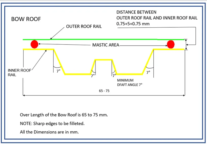
As per the same procedure of design the centre roof is repeated in the design of bow roof but the location is some distance is given for intersecting the surface from the centre roof. The final surface is shown below.
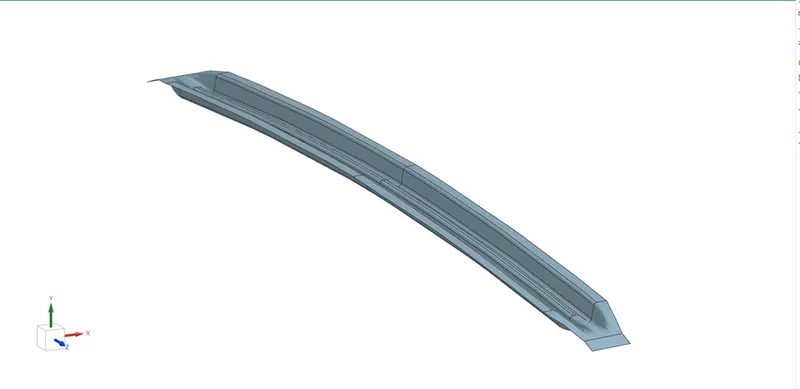
Then the surface is thickened by 0.75mm for make the bow roof part. In the roof design there are 2 bow roofs are designed. The resultant bow roof’s part is shown below.
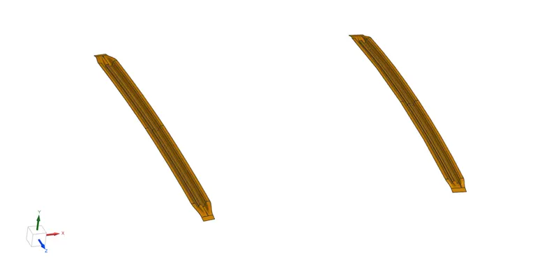
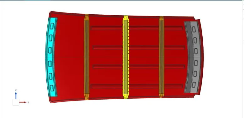
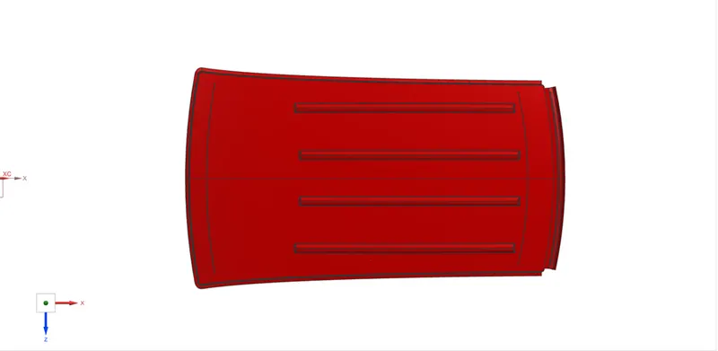
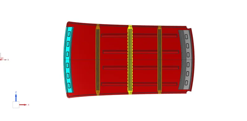
By designing all the parts, they are assembled and the final Roof is designed as shown below.
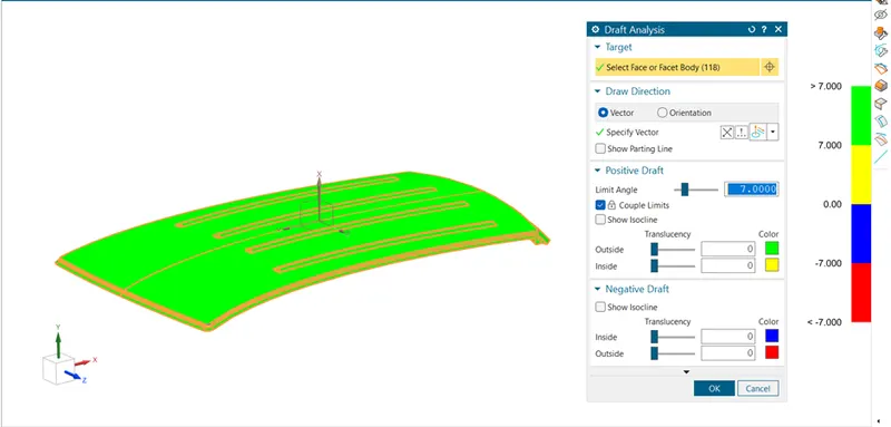
DRAFT ANALYSIS:
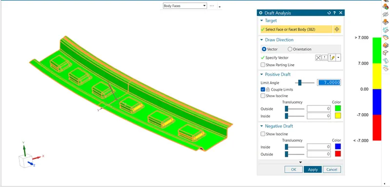
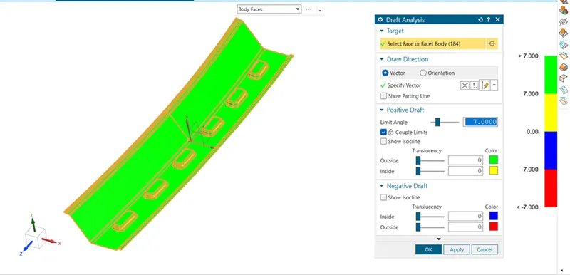
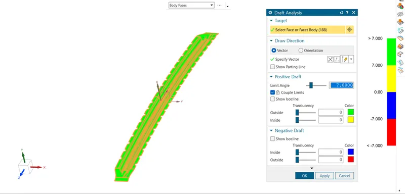
The draft analysis technique is used to analyse whether our part model created in CAD is manufacturable based on the draft condition applied. Here the part should get easily removed from the panel dies (in case of Sheet metal part) or Mold (in case of plastic).
No parts can be ejected from the tool if it is having a straight 90-degree profile from its base surface. A small draft angle is provided to each and every area of the component in order to get easy removal of the component from the tool.
Here we are providing a direction in which components should eject in order to get easy removal of components from the tool. In other words, it also lets us know whether the model is having a draft angle and how much is the draft angle from the tool direction.
DRAFT ANALYSIS ON ROOF:
In this design draft analysis are made in every part individually whether it is OK or not for Production. Here Minimum angle is 70 provided for every draft analysis. For every analysis the part should turn into green.
OUTER ROOF:
FRONT ROOF RAIL:
REAR ROOF RAIL:
CENTRE ROOF RAIL:
BOW ROOF:
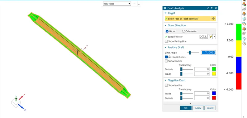
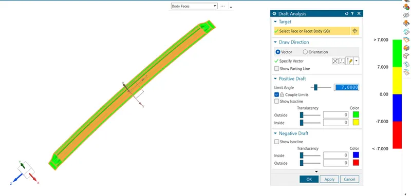
CALCULATION:
HEAT DISTORTION ANALYSIS:
This analysis is used to examine which the metal softens and deforms under a specific load. This study is done to check the ability of the roof to withstand high temperatures concerning the positioning of the reinforcements which contribute to increased strength.
The formula for this analysis is
W = [1.73 x 10^(-3) x L] + [1.85 x 10^(-8) x (R^2)/t] + [ 1.10x10^(-3) x l] - 2.68
Where,
L = Roof Length in X-Direction[mm](Roof dimension in 0-Y)
R = Roof curvature
R = 2(Rx*Ry)/(Rx+Ry)
Rx = X curvature
Ry = Y curvature
t = Roof plate thickness [mm]
l = Bow Roof Span [mm]
To find the value of above specifications sketch is drawn in the roof as shown below.
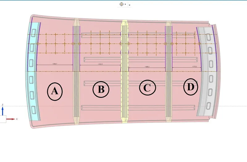
In the above sketch the points are created by offset line, intersection point and mid-point. And also, the value of L and I are calculated.
Then the points are projected on the surface and the three-point arc is drawn in it for calculated the value of Rx and Ry by local radius command.
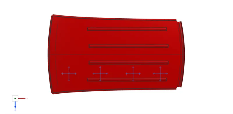
For this analysis the value of L and t is constant.
L = 2049.2mm
t = 0.75mm
Here there is 4 calculation is made by 4 sections in it.
FOR SECTION A:
L = 2049.2mm
t = 0.75mm
I = 394.7mm
R = 2(Rx*Ry)/(Rx+Ry)
Rx = 5732.35mm
Ry = 2655.18mm
R = 2(5732.35*2655.18)/(5732.35+2655.18)
= 3629.29
W = [1.73 x 10^(-3) x L] + [1.85 x 10^(-8) x (R^2)/t] + [ 1.10x10^(-3) x l] - 2.68
W = [1.73 x 10^(-3) x 2049.2] + [1.85 x 10^(-8) x (3629.29^2)/0.75] + [ 1.10x10^(-3) x 394.7] - 2.68
W = 3.54 + 0.32 + 0.43 – 2.68
W = 1.61
Similar steps are done in other 3 sections. The resultant W values is shown in below.
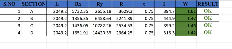
Above table the value of W is in judgement condition <2.7. Hence this Roof design is Pass the Heat distortion analysis.
SNOW LOAD ANALYSIS:
The purpose behind this analysis is to check the strength of the roof when snow is present on it acting as a load. A roof should be designed in such a way that it should rebound to its original shape after the removal of snow.
Formula for snow load analysis is
Qr = [Iy x t2] / [α x s x [(Rx + Ry)/2]2 x 10-8]
Where,
α = My x Lx2 x 10-12 , My = Y(Ly-Y)
t = Roof plate thickness [mm]
Ly = Distance between the front and rear roof Rails on the Vehicle along with 0Y[mm]
Length of Roof panel with the centre point between Roof rail Front /Rear as the front and rear reference point.
Lx = Distance between the Left and Right end of the roof on the Roof BOW [mm]
The width of the roof panel is exposed on the surface.
Y = Distance front Front Roof Rail to Roof BOW[mm]
s = Distance for which Roof BOW bears divided load [mm]
s = L1/2 + L2/2
Iy = Geometrical moment of inertia of Roof BOW (Y cross-section)[mm4]
Rx = Lateral direction curvature radius of roof panel Y cross-section on Roof BOW [mm]
Roof panel curvature Radius of the Length Lx in Front view
Ry = Longitudinal Direction curvature radius of the Roof panel X cross-section on Roof BOW [mm]
Roof panel X curvature radius of length s in Side view
For this analysis there is only 3 calculations made in 3 sections.
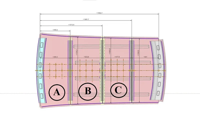
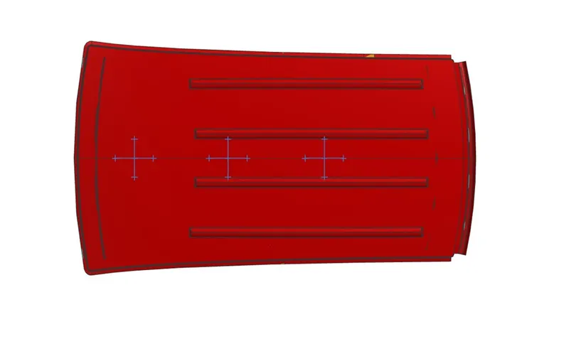
For the value of Rx and Ry the procedure done in heat analysis is applied here but the curve origin are taken in the centre line of the roof which shown below.
Here t and Ly value is constant.
t = 0.75mm
Ly = 1932.7mm
FOR SECTION A:
Qr = [Iy x t2] / [α x s x [(Rx + Ry)/2]2 x 10-8]
Iy = 5577.57
Rx = 4494.64
Ry = 2652.72
s = L1/2 + L2/2
= 490.3/2 + 523.6/2
= 506.95
α = My x Lx2 x 10-12
My = Y(Ly-Y)
= 490.3(1932.7-490.3)
= 707208.7
Lx2 = 1219257.64
α = 707208.7 x 1219257.64 x 10-12
= 0.86227
Qr = [5577.57 x (0.75)2] / [0.86227 x 506.95 x [(4494.64 + 2652.72)/2]2 x 10-8]
= 3137.38 / (0.86227 x 506.95 x 0.127)
= 3137.38 / 55.51
Qr = 56 (approximately)
Qr = 56 > 3.1
Hence this section is passed the snow load analysis.
Above steps are repeated for the next two sections and their result is shown below.

From above table shown that the Roof design is passed the Snow load analysis in all section and the Roof design is OK.
CONCLUSION:
Thus, the Roof is designed by given Master section with required Bow roofs assembled in it. Also, the designed Roof is checked for Heat distortion and Snow load criteria, in that analysis Designed Roof is Passed in both criteria and the design is OK.
Isometric view:
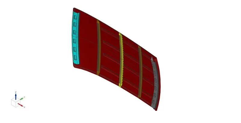
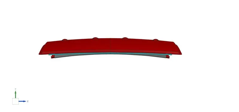
Front view:
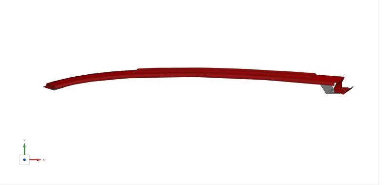
Side view:
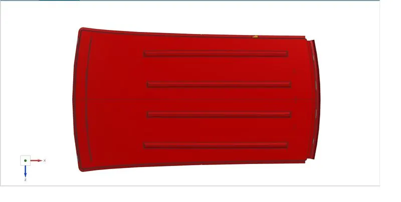
Top view:
Bottom view: