Wiring harness design in CATIA V5 - 3D modeling Week 4 Challenge
WIRING HARNESS DESIGN 3D MODELLING WEEK 4 CHALLENGE
AIM:
To Design the wiring harness by given parameters and connector in the CATIA Electrical Workbench and also add the Suitable protective cover for it.
QUESTION 1:
Route the following harness layout in Electrical workbench. Make assumption for harness bundle diameters. Use Following connectors as shown in layout diagram.
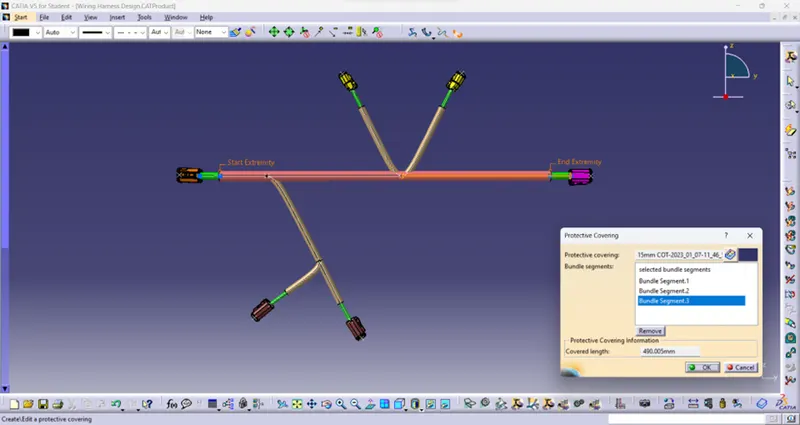
Add protective covering on all branches connected to DT06-2S & DT06-4S connectors. Keep end extremity at 30mm (from connectors end).
GIVEN CONNECTORS:
- DT06-4S
- DT06-6S
- DT06-2S
- DT06-08SA
These connectors 3D Data are downloaded from www.te.com.
GIVEN WIRING PARAMETERS:
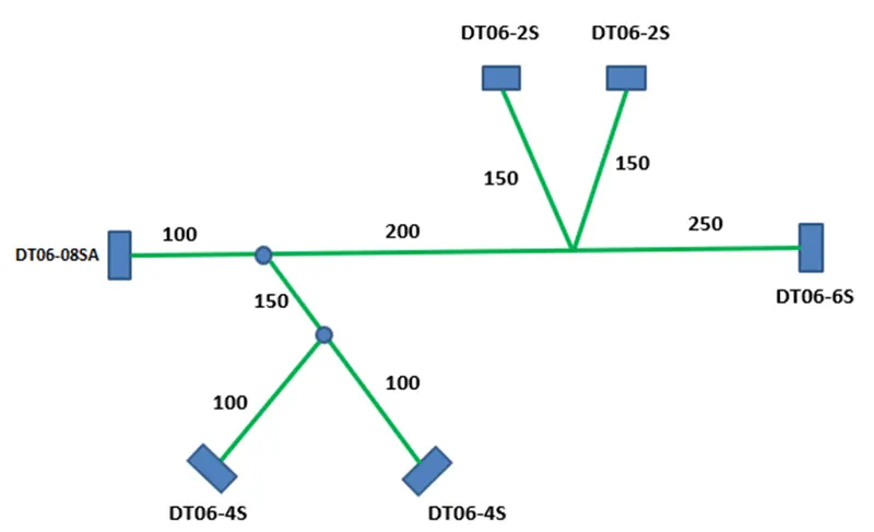
DESIGN OF WIRING HARNESS:
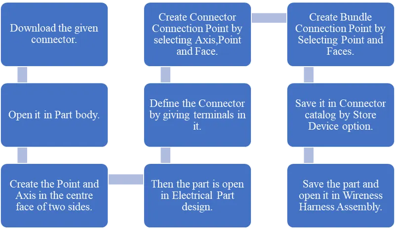
ELECTRICAL DEFINITION OF CONNECTORS:
By following the below steps the given connectors are made electrically defined for wiring harness.
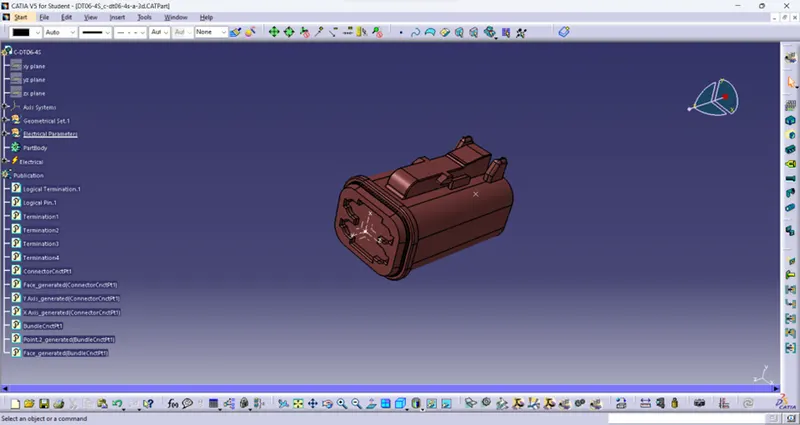
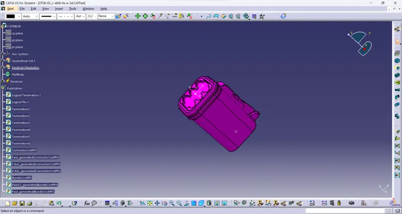
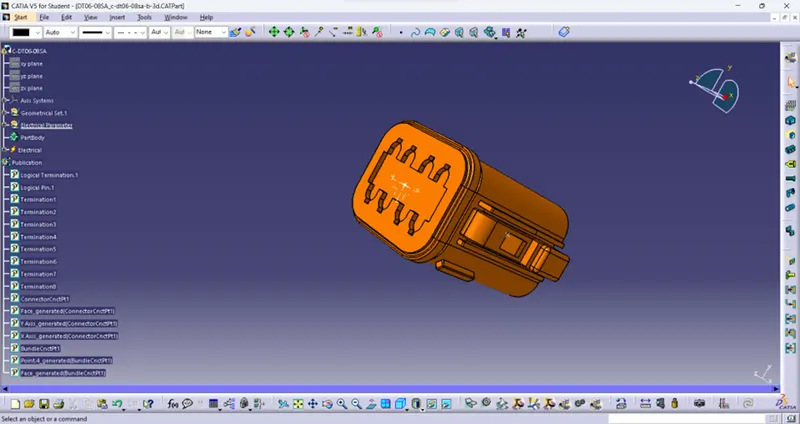
Electrically defined connectors of given connectors are shown below with feature tree.
DT06-2S:
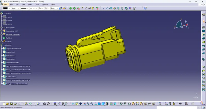
DT06-4S:
DT06-6S:
DT06-08SA:
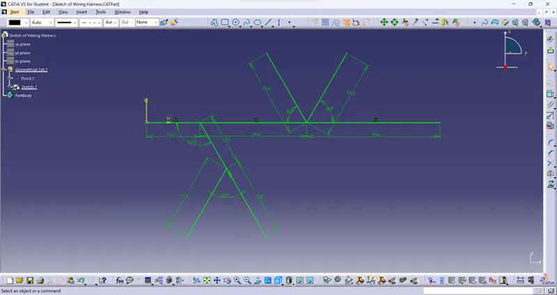
Design of Reference Sketch:
For Placing the connectors approximately in given parameters there is reference sketch is created as shown below.
WIRING HARNESS:
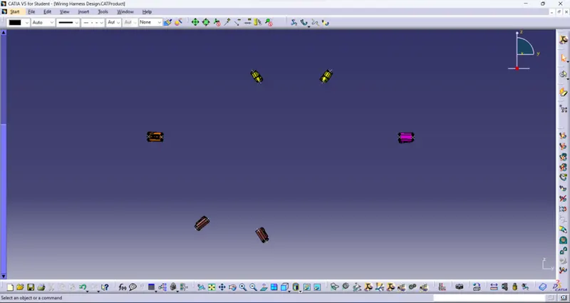
All the connectors are opened in Wiring harness Assembly and placed in it approximately by using the reference sketch as shown below.
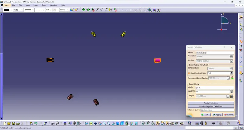
By clicked Geometrical bundle and select the Assemble part then electrical definition is done in assemble section. Then by click Branch definition diameter as 10mm, bent radius as 1.4mm values are given and click Route definition select the two connectors for wiring harness as shown below.
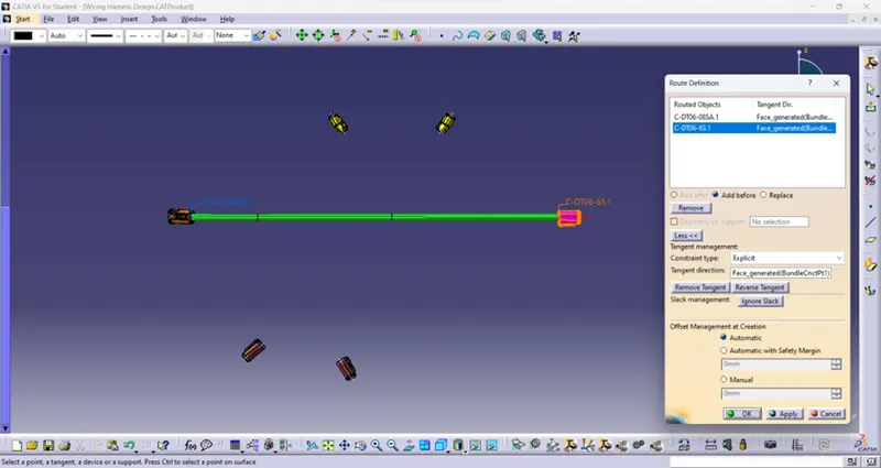
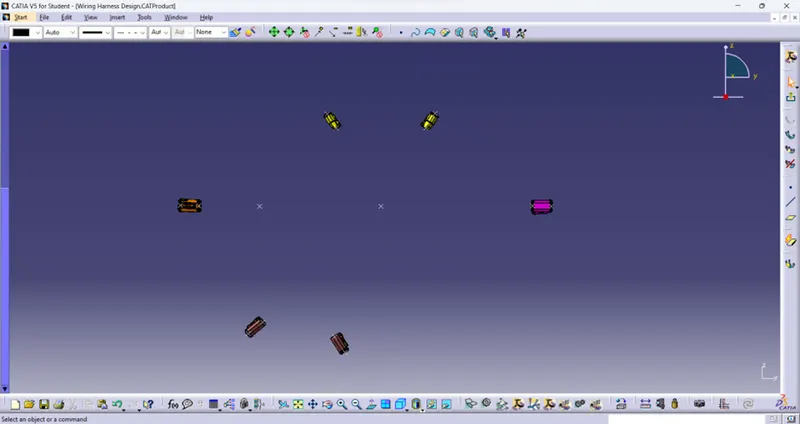
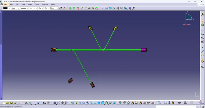
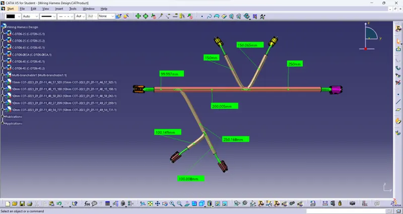
By selecting Add Branch Point icon the branch is divided by two points in dimensions are 100mm and 250mm from Start and End point respectively as shown below.
Following above routing definition method wiring harness is done by connecting wire with connector with diameter 5mm as shown below.
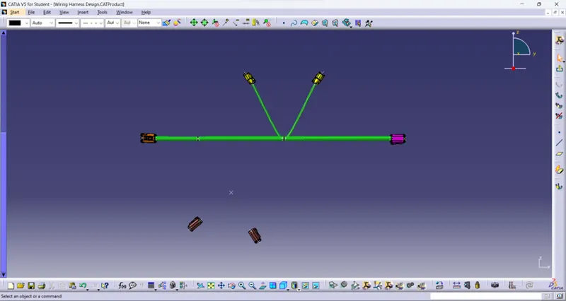
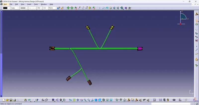
Repeating Add Branch Point step for create point with 150mm in the branch to connect the connector through wire as shown below.
Then by routing definition as radius value 5mm wiring harness is done as shown below.
ADDING PROTECTIVE COVER:
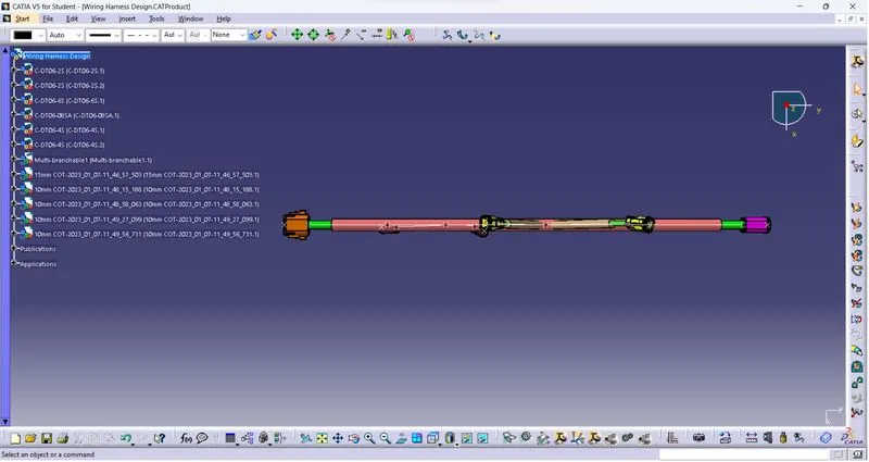
Here for 10mm wire 15mm Protective cover is used and for 5mm wire 10mm protective cover is used. Also End extremity value 30mm is given as shown below.
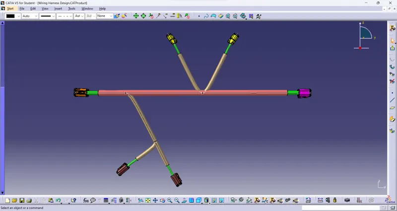
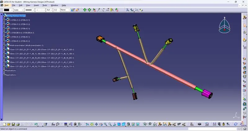
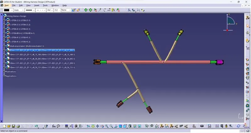
The final part having wiring harness with dimension as shown below.
CONCLUSION:
Thus, the Wiring harness design is done by given connectors and parameters in CATIA and also Protective cover is added into it.
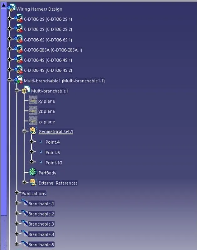
Feature tree 1:
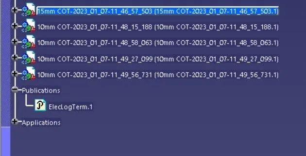
Feature tree 2:
Isometric View:
Front View:
Top View: