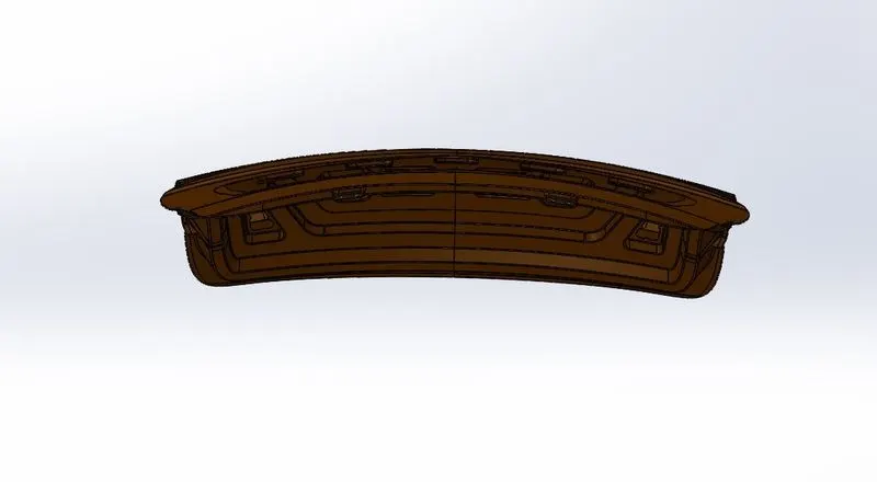
Design of backdoor
BACK DOOR
AIM:
To create the Back door and an ASSEMBLE parts by developing the essential flanges creating the reinforcements also perform Draft analysis.
DESIGN APPROACH:
INTRODUCTION:
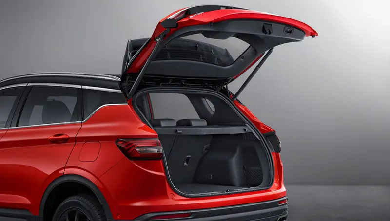
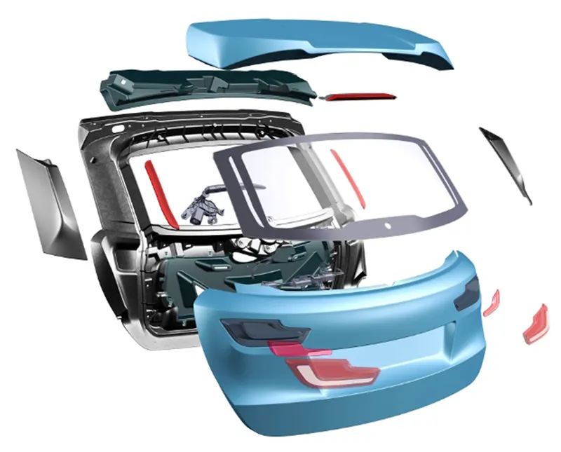
Back Door is also referred as 'Hatch' or 'Tailgate' or 'Trunk-lid' or 'Boot-door'. It’s the rearmost part of the vehicle which gives access to the trunk and has mounts for tail lamps, hinges, wiper motor, gas stay etc. These doors can be operated manually or electric powered. In most of the luxury car’s door is electrically operated.
TYPES OF BACKDOOR:
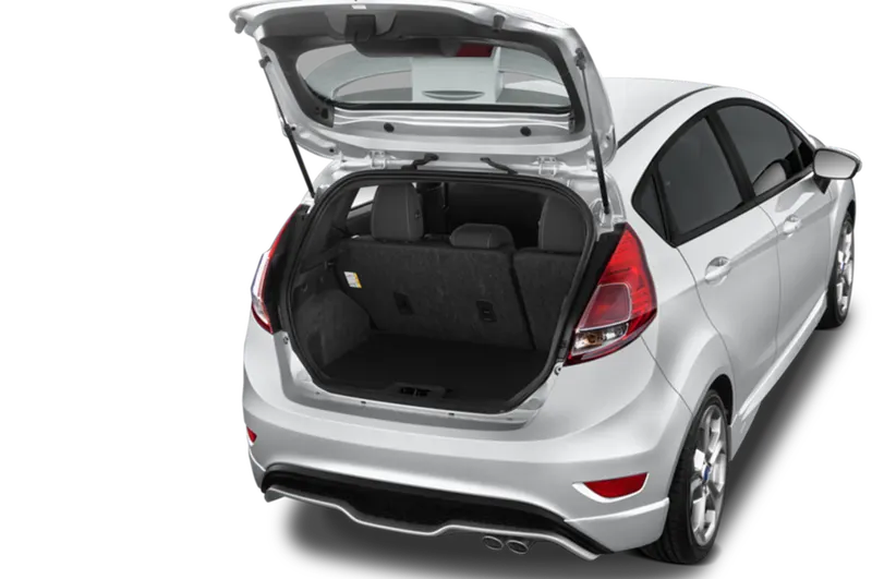
TOP MOUNTED BACKDOOR:
These types of back doors are used in a station wagon, pickup truck and some other sports utility vehicles. Today’s modern cars use top mounted tailgating systems which are both powered and also gas stay supported. These tailgates provide greater rear visibility compared to other types.
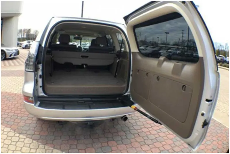
SIDE MOUNTED BACKDOOR:
It is generally used in van type MPVs, SUVs, pickup truck vehicles. These side mounted door/barn doors are a lot easier compared to top mounted ones. These doors are generally small in size and can be easily accessed. These doors are more convenient for the goods handlers carrying lengthy objects, long pipes where one door is kept open.
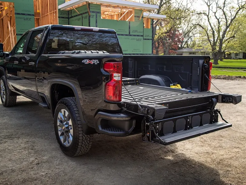
BOTTOM MOUNTED:
Bottom type or split type backdoor system is used in estate type cars, pickup trucks and some luxury SUVs. These are most convenient type of backdoor in which the bottom split is used as a support or even as a table for the touring people.
MATERIAL SELECTION:
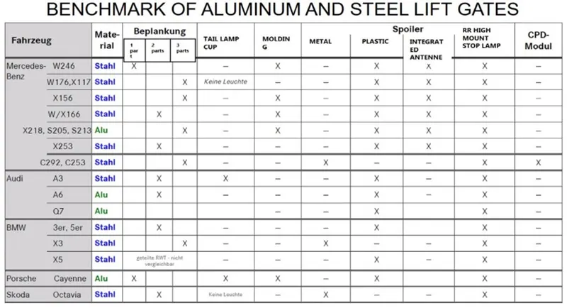
The Material selection play a major role in determine the overall weight of the back door. The materials generally used are Steel and Aluminium. The Density of Steel is higher than Aluminium thus it results in adding more weight of the door. Basically, the material is used based on the budget of the car, because the cost of steel very cheap than Aluminium.
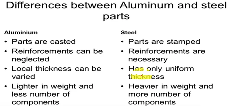
If aluminium is used instead of steel there is no need of many parts like Reinforcements for each mounting and the overall weight geta reduced by 6-10 kg approximately. But the drawback is Aluminium is much costlier than Steel. Hence based on the budget of the car aluminium is used. In higher end models like Benz, Audi, Porsche and BMW we can find aluminium is used instead of steel resulting in reduced weight and increased performance of the vehicle.
Another Factor to make a note is using Casted Aluminium instead of deep drawn Steel components and adding reinforcements to it is the space of the luggage commodity gets increased by a certain amount because the draft angle for Casted aluminium is much lesser (3 degree) than the deep drawn Steel inner panel (7-9 degree). Thus, it reduces the space between the inner and outer panel resulting in much larger cabin space than the deep drawn steel inner panel. Thus, the material selection is one of the design considerations taken.
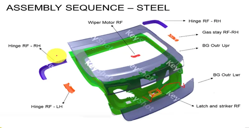
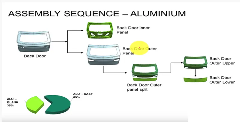
Since it reduces the space between the inner and the outer panel the rear visibility of the car is also improved giving more space for the mirror to view. Hence in this design the material chosen is steel since it is designed for a medium budget car and hence high cost could not be afforded to design the back door.
TEST AND LOAD DISSIPATION:
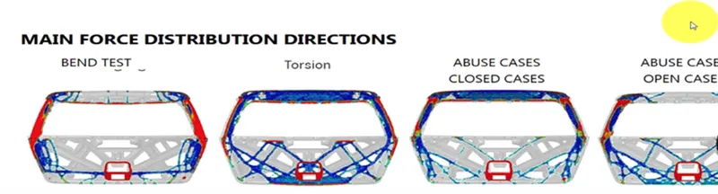
Backdoor is tested in several ways which is shown below.
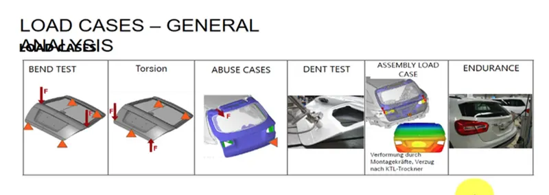
Also, in designing embosses is created for force distribution in all ways to avoid damage in back door and also for safety of passenger. The below image shown the force distribution areas in test.
PARTS OF BACKDOOR:
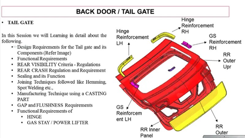
- Inner Panel
- Outer panel upper
- Outer panel lower
- Hinge Reinforcement
- Gas stay Reinforcement
- Wiper Reinforcement
- Latch Reinforcement
DESIGNING OF BACKDOOR:
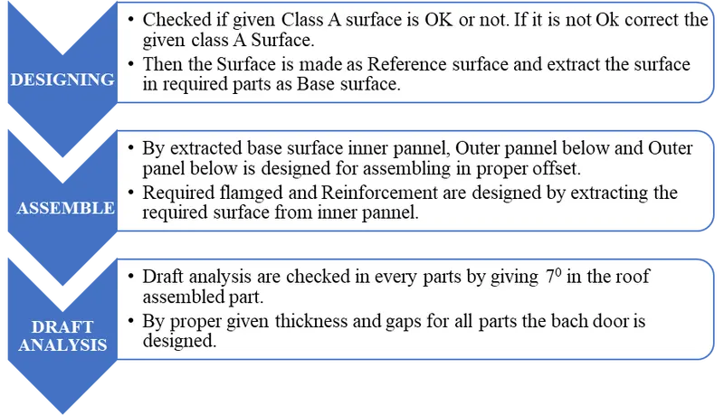
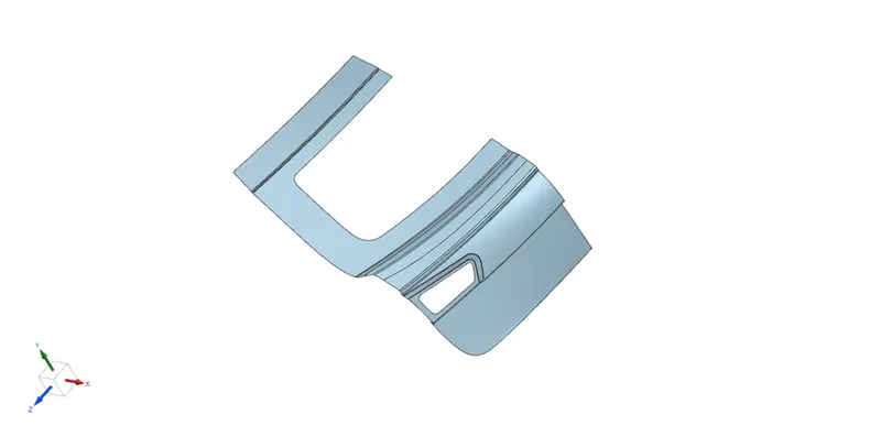
All the parts in the back door are designed from the given Class A Surface. Before designing the backdoor the given surface is checked and corrected the surface which does not have any overlap surfaces. The resultant surface is shown below.
OUTER PANEL UPPER:
In the given surface there is two surfaces upper and lower here the upper surface is extracted in Outer panel upper part by Wave geometry link which is shown below.
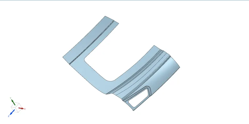
Sharp corner is trimmed by bridge curve and the lower surface is trimmed by 10mm offset to provide gap for lower panel. The surface is offset in 0mm and the curve is offset in 10mm and that surface is offset in 2.65mm (thickness of outer panel 0.75+0.75, inner panel 0.75 and gap between panel 0.2+0.2) for creating bottom surface. The resultant surface is shown below.
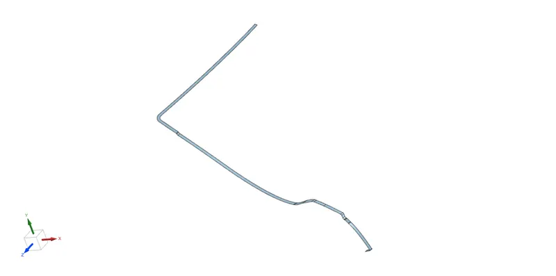
By using bridge curve and sweep surface command the surface is created between the two surfaces.
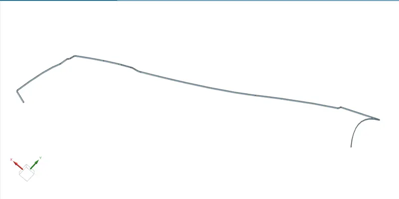
Then all the surface are sewing and by bridge curve trimmed the bottom surface for provide corner relief for hemming.
Hemming:
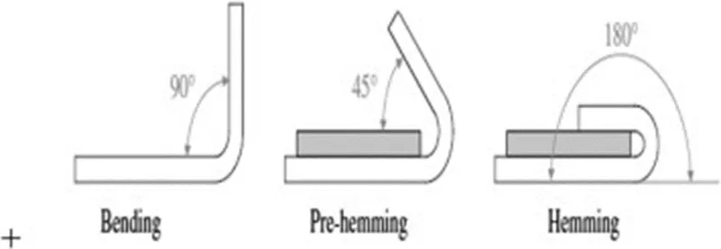
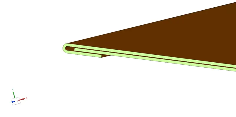
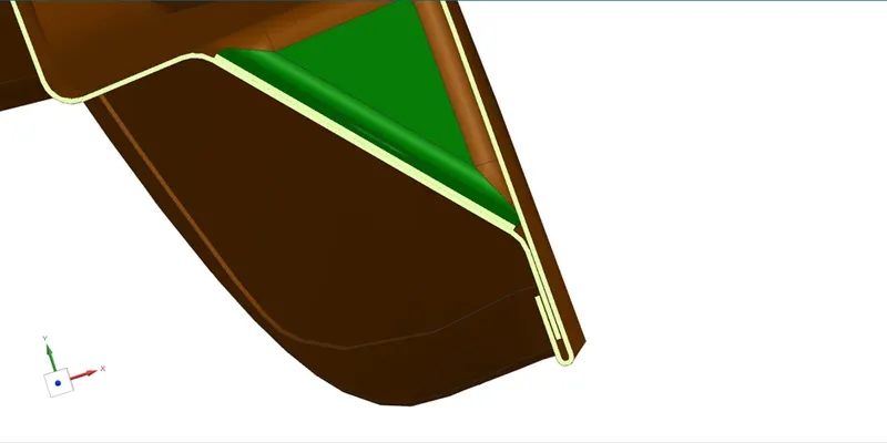
Hemming is a forming operation in which the edges of the sheet are folded or folded over another part in order to achieve a tight fit. Normally hemming operations are used to connect parts together, to improve the appearance of a part and to reinforce part edges.
The surface is mirrored and the resultant outer panel upper is shown below.
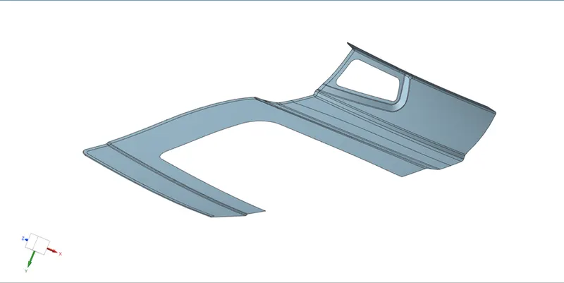
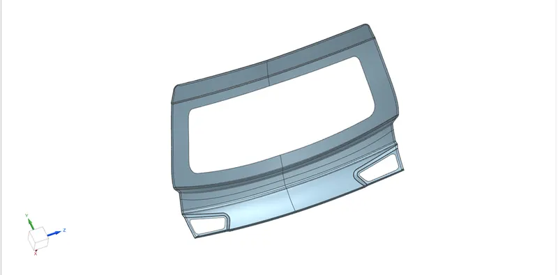
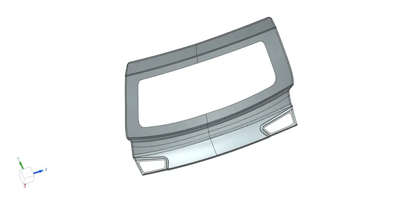
By thickened the surface by 0.75mm final part of the outer panel upper is designed.
OUTER PANEL LOWER:
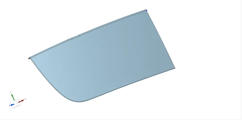
In the reference surface the lower part is extracted in this part file by wave geometry link which is shown below.
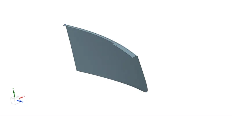
By repeating the same procedure of outer panel upper the surface is offset and connected by sweep surfaces.
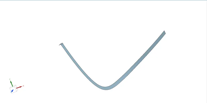
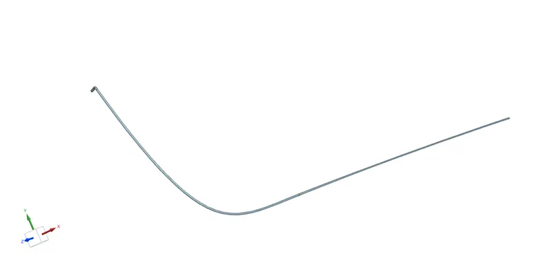
The resultant surface is shown below and mirrored it for final surface.
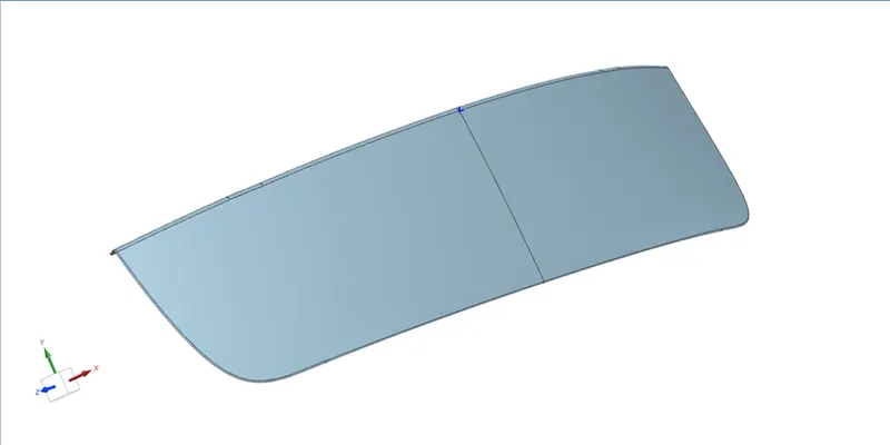
Then the surface is thickened by 0.75mm for designed the resultant part.
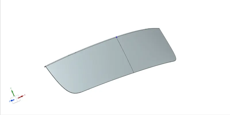
INNER PANEL:
Inner panel had both upper and lower surfaces as reference surface as shown in below.
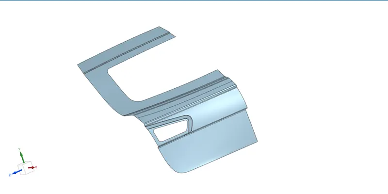
Initially tooling axis is created in the surface for further process.
Tooling Axis:
Axis which drafts the part from certain angle is called tooling axis. Here two lines are drawn from starting point to middle point and middle point to end point. Then the lines is drawn which derived line. That line is Tooling axis which shown below.
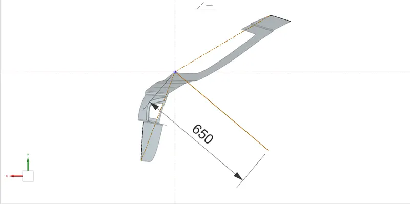
Reference surface will offset by 1.7mm (outer panel thickness 0.75, gap 0.2 and inner panel thickness 0.75) which is working surface for inner panel.
Sealant Flange:
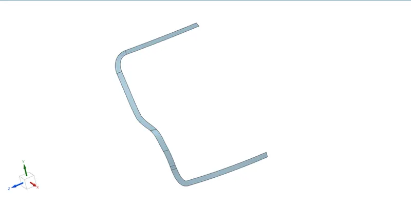
Both upper and lower surfaces are offset by 35 and 60mm respectively for sealing flanges. For upper the surface is trimmed by offset the curve for 60mm in side and 30mm for top. For bottom sketch is drawn in required shape od flange and project it in the surface. Then the surface is trimmed by that curve and connect both upper and lower surface by bridge curve and through curve mesh and sew it. The resultant sealant flange is shown below.
Connecting Flange:
By using law of extension and trim surface sealant flange and offset surface of reference surface are connected as shown below.
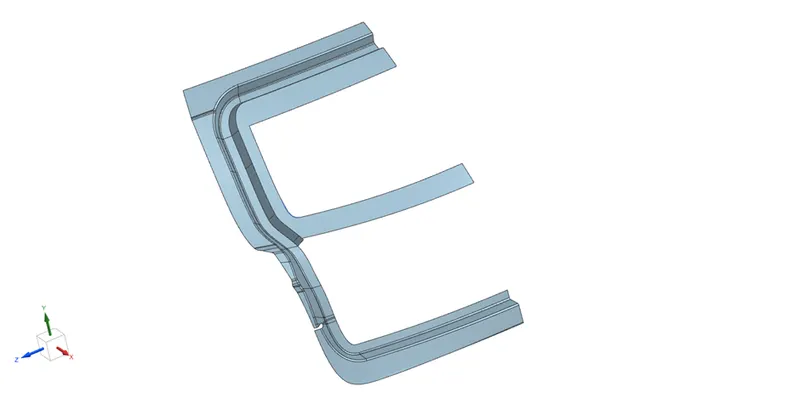
Then the surface is created by law extension in the lower part and trimmed it with lower reference surface.
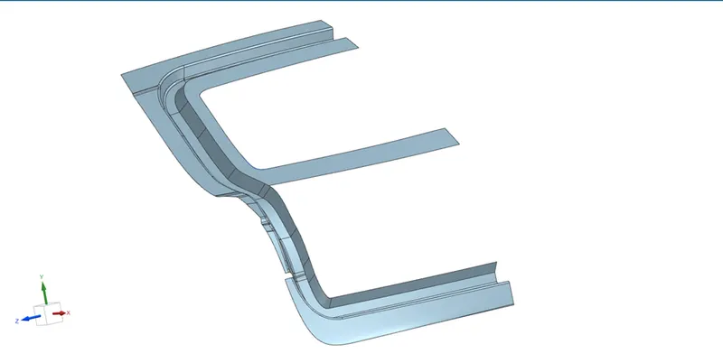
By creating bridge curve, extend sheet and trim sheet the surface is created in lower part and the sharp edges are blended in the surface.
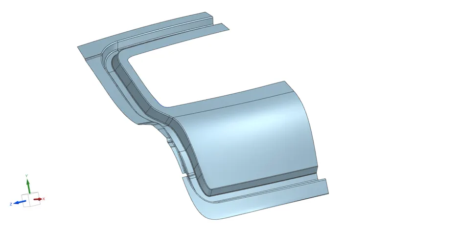
Reinforcement Cut:
Plane is created in required place and sketch is drawn having line. Law extension is used to create plain surface by line and trimmed in corners. Then the surface is created in by law extension by tooling axis and trimmed it with the surface to create the Reinforcement cut which is shown below.
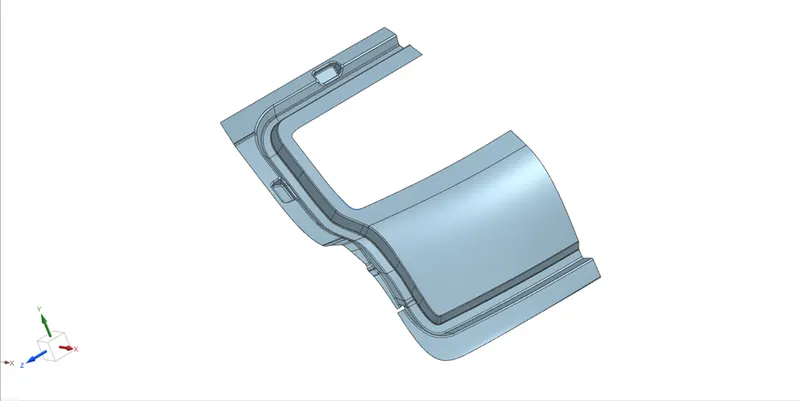
Cut-out Section:
Rectangular shape is created by sketch and project in the surface is trimmed then the surface is created by law extension in perpendicular to the surface. Then lower reference surface trimmed in rectangular shape as drawn in surface. Then both surface is trimmed together to create the cut-out section as shown below.
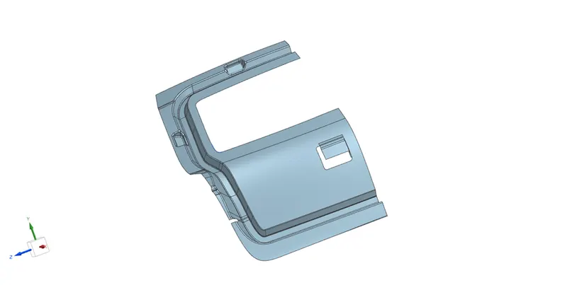
Emboss:
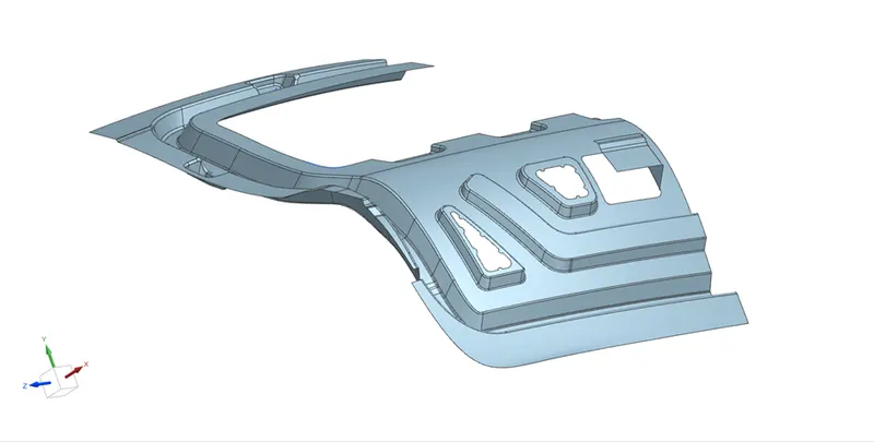
Embosses are created in surfaces by projecting sketch in the surface for strengthen the part and also provide force dissipation in all side and trimmed in it to reduce the weight of sheet and edges are blended. Here one embosses is created for wiper reinforcement. The resultant process is shown below.
Holes in Reinforcement:
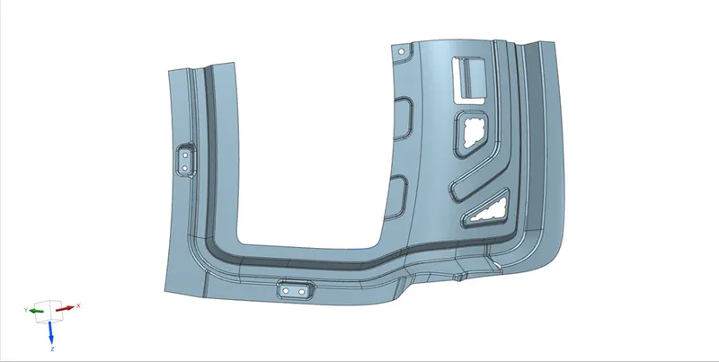
By creating plane in reinforcement cut sketch is drawn which is circular in shape and project in it and trimmed it as shown below.
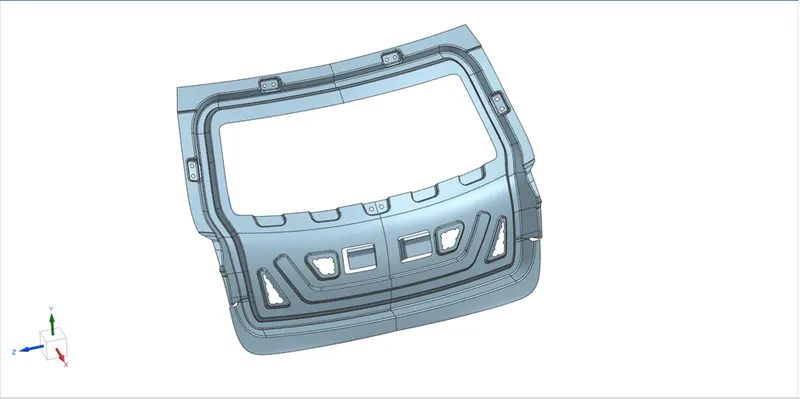
Then the surface is extended little bit and trimmed with the origin plane for fill the gap for mirroring. One side of surface is mirrored with origin plane and sewed it. By using bridge curve and trim sheet sharp corners are trimmed.
Trajectory Path:
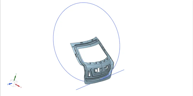
This is the path which defines the direction of backdoor closed. It is done by creating midpoint between the two holes of the hinge reinforcement. Then from that midpoint circle is drawn having radius of the latch is placed. Tangent line is drawn in it and the point which circle, tangent line and surface are intersect is the midpoint of the latch which is shown below.
For latch reinforcement the same step is followed here which is mentioned above by creating plane in the centre of the surface cut out for reinforcement is made and all the edges are blended having radius 4 to 5mm. Final surface of inner panel is shown below.
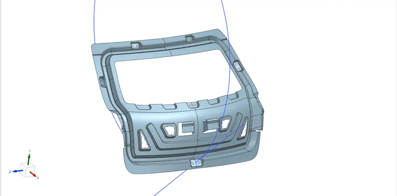
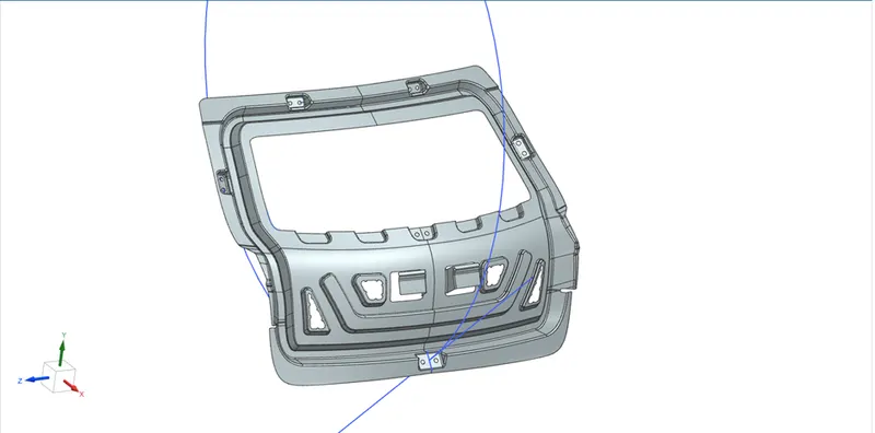
Finally inner panel surface is thickened by 0.75mm.
Reinforcement:
There are four reinforcements in it.
- Hinge Reinforcement
- Gas stay Reinforcement
- Wiper Reinforcement
- Latch Reinforcement
All the reinforcements are made in same way which the required surfaces are extract by Wave geometry link in their individual part files. Then the surface is offset by 0.75mm towards inward of inner panel and sharp edges are trimmed. Final surfaces are thickened by 0.75mm and the reinforcements are shown below.
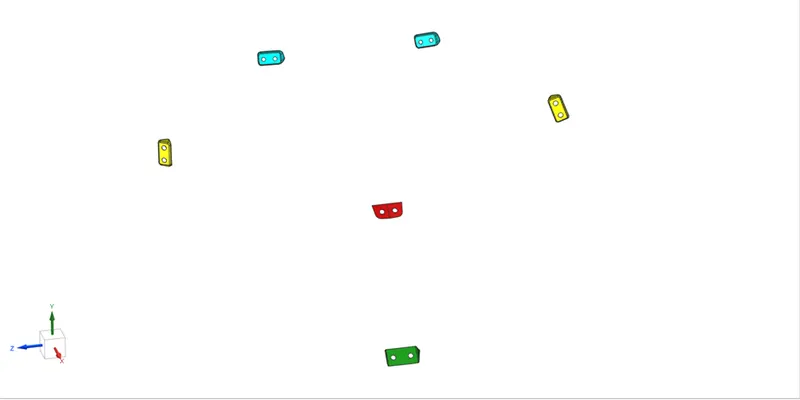
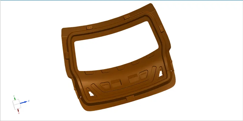
Inner panel with having reinforcements.
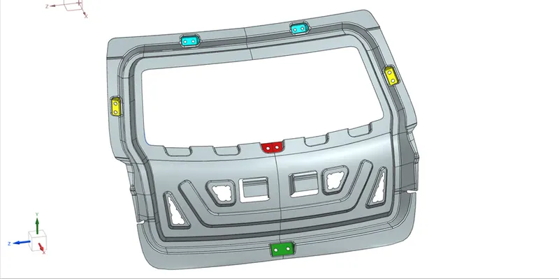
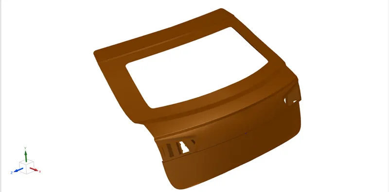
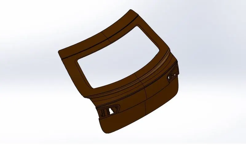
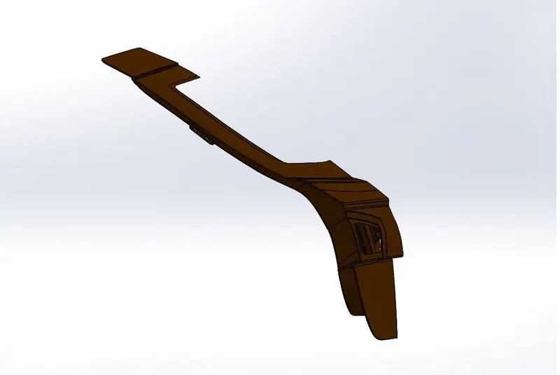
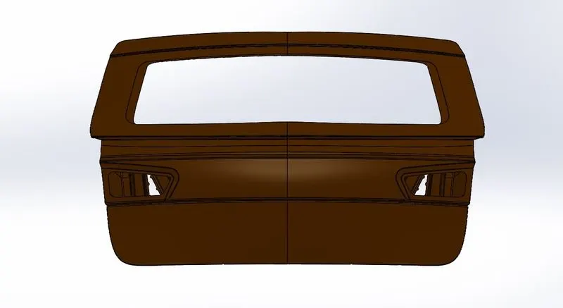
The final backdoor with assemble is shown below.
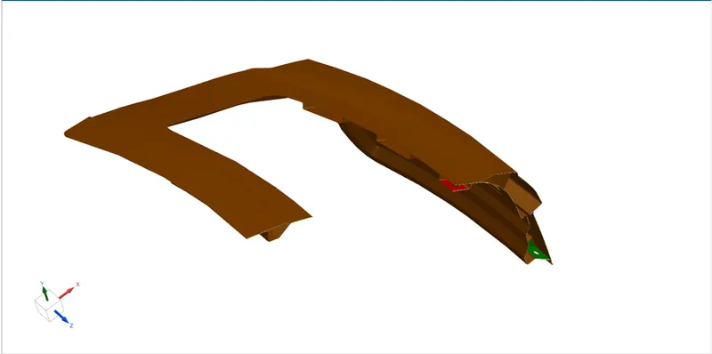
CROSS SECTION VIEW:
DRAFT ANALYSIS:
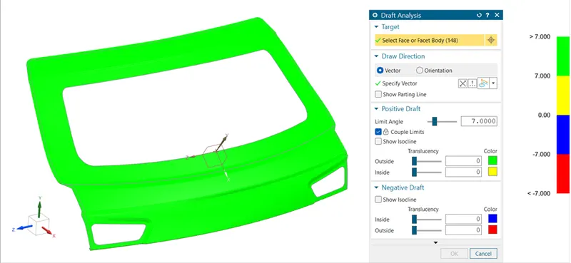
The draft analysis technique is used to analyse whether our part model created in CAD is manufacturable based on the draft condition applied. Here the part should get easily removed from the panel dies (in case of Sheet metal part) or Mold (in case of plastic).
No parts can be ejected from the tool if it is having a straight 90-degree profile from its base surface. A small draft angle is provided to each and every area of the component in order to get easy removal of the component from the tool.
Here we are providing a direction in which components should eject in order to get easy removal of components from the tool. In other words, it also lets us know whether the model is having a draft angle and how much is the draft angle from the tool direction.
DRAFT ANALYSIS ON BACKDOOR:
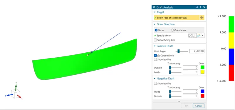
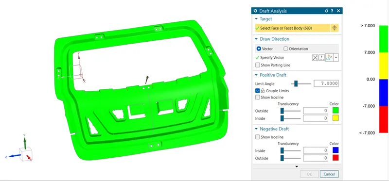
In this design draft analysis are made in every part individually whether it is OK or not for Production. Here Minimum angle is 70 provided for every draft analysis. For every analysis the part should turn into Green.
OUTER PANEL UPPER:
OUTER PANEL LOWER:
INNER PANEL:
CONCLUSION:
Thus, the Backdoor is designed by given Class A surface with Assemble and Reinforcements also Draft analysis is performed.
Isometric View:
Front view:
Side view:
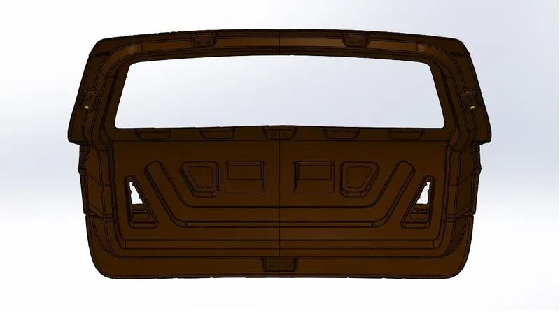
Top view: