Wiring harness design in CATIA V5 - 3D modeling Week 2 Challenge
3D MODELLING WIRING HARNESS DESIGN CHALLENGE – WEEK 2
AIM:
To design the wiring harness part defining them and assemble it by downloading given part files.
DESIGN APPROACH:
INTRODUCTION:
Wiring harness is the combination of electrical and mechanical CAD to connect all the electrical parts in the automotive at the optimum level. It mainly consists of an electrical harness and the mechanical harness in the design. CATIA V5 electrical workbench is used as the CAD tool for routing the wires.
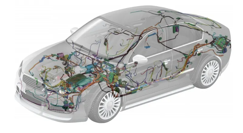
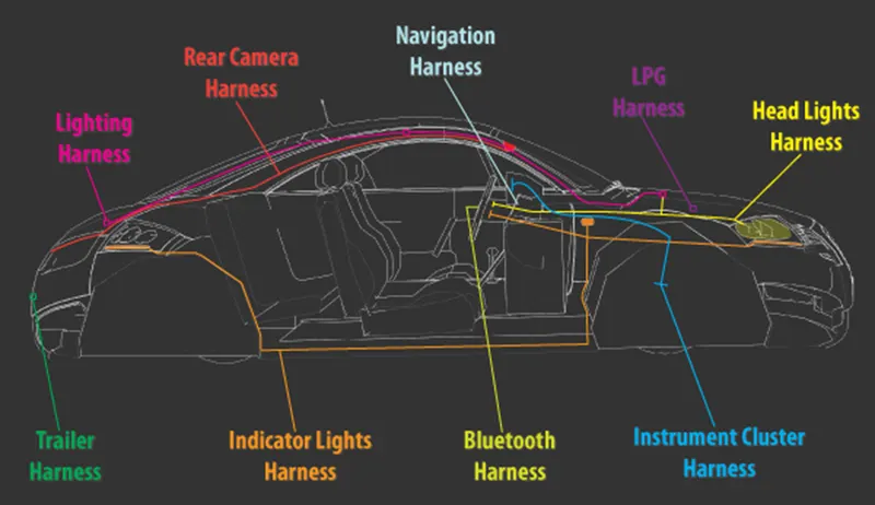
The function of wire harness in the whole vehicle is to transmit or exchange the power signal or data signal of the electrical system to realize the functions and requirements of the electrical system.
ELECTRICAL DISTRIBUTION SYSTEM (EDS):
It deals with physical (location of electronic components placed in the vehicle, front end to back end) and logical (different Electrical Control Units) architecture, schematic development, power distribution (set with fuses to check wiring harness is safe in various failure modes), wiring harness design and wiring harness component design of given electrical system.
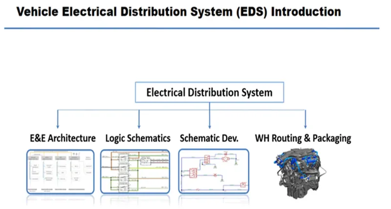
TYPES OF DESIGN FLOW OF EDS SYSTEM:
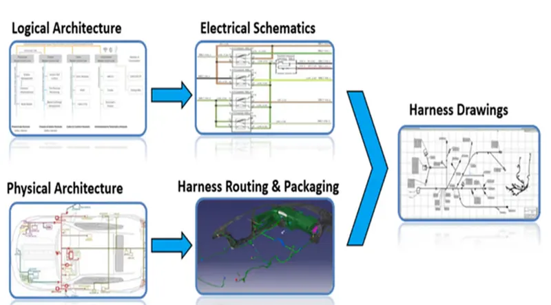
LOGICAL SCHEMATICS:
It is detailed design of E&E architecture which is extended to show the logical connectivity between different components and controls of different systems and sub-systems.
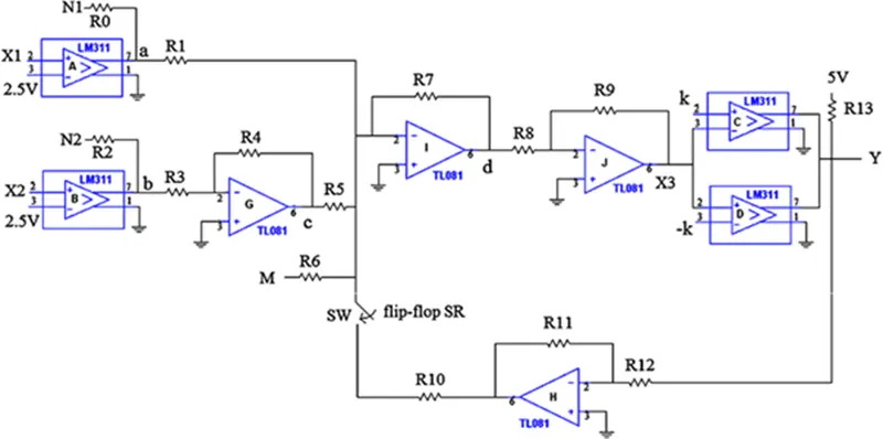
PHYSICAL ARCHITECTURE:
It means the physical location of the electrical component place inside the vehicle.
E & E ARCHITECTURE:
It is the high-level logical connectivity diagram. It represents all the systems, sub-systems and logical connections between them. It shows the Control Area Network (CAN) between different electronic components.
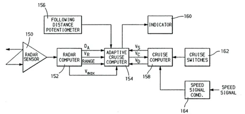
LOGICAL ARCHITECTURE:
It means the connectivity of those component in logical level. Example: connectivity between various sensors with ECU (electronic control unit).
POWER DISTRIBUTION:
It deals with distribution of power from the battery to the different component which will be distributed with the help of different types of fuses to ensure the wiring harness is safe when there is occurrence of different failure modes.
ELECTRICAL SCHEMATICS:
It is detailed design of logical schematics, which describe the pin-to-pin connectivity, properties, fusion distribution, grounding distribution, wire properties (wire type, colour, gauge), interconnects, circuit properties (circuit numbers, connector designation numbers, control device number), specification of component (rating od diode, resistors) etc., This is the end design of electrical core design of system and used as primary input for harness development.
WIRING HARNESS TOPOLOGY:
Wiring harness topology is the strategy to divide or split the harness between different pieces to achieve the best manufacturability, serviceability and cost effective.
WIRING HARNESS ROUTING:
It deals with the desired path of wiring harness into a given vehicle environment by applying the set of design rules and industry practices, some of the design rules are harness must be kept away from the exhaust, engine radiators, brake lining.
WIRING HARNESS PACKING:
It deals with the fixing / mounting strategy of wiring harness routing to ensure the safe and reliability of wiring harness by applying a set of design rules. Some of the design rules are wire bend radius, clamping distance etc.
WIRING HARNESS ASSEMBLY PARTS:
- Wires
- Connectors
- Fuse and relay box
- Terminals
- Clips and Clamps
- Electronic component
- Guiding channel
- Retention device
- Insulation
- Protection covering
DESIGNING OF WIRING HARNESS:
Before designing the wiring, harness there should be CATALOGUE folder which is created in the CATIA software.
CATALOGUE CREATION:
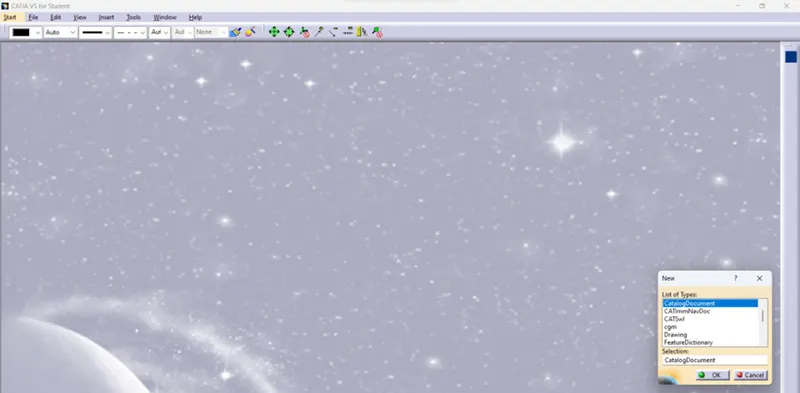
Initially required files to be created by Option --> New --> CatalogDocuments shown in below.
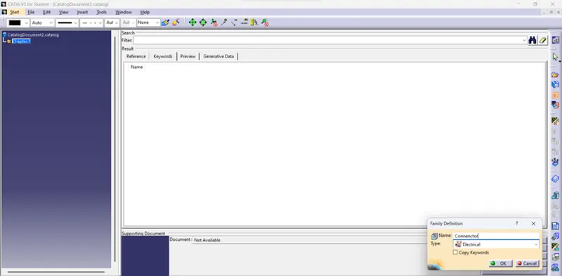
Then by clicking Add family --> Connector as Name and Electrical as Type and click Ok. Then it is saved in Catalogue folder as shown below.
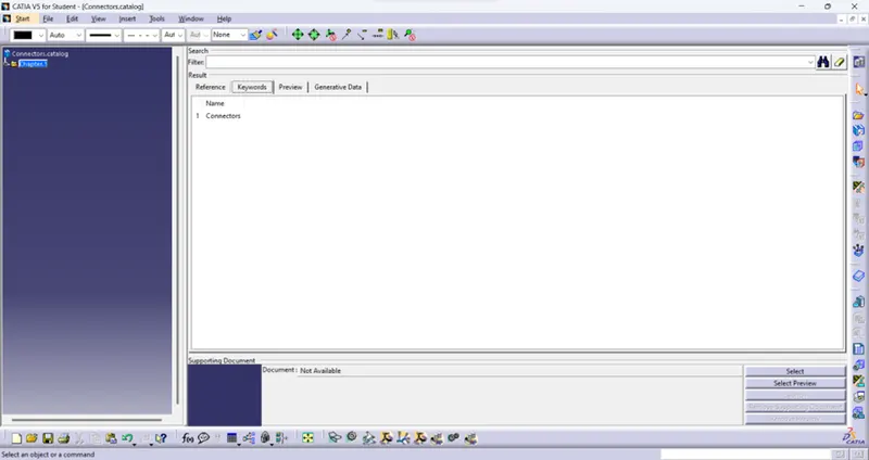
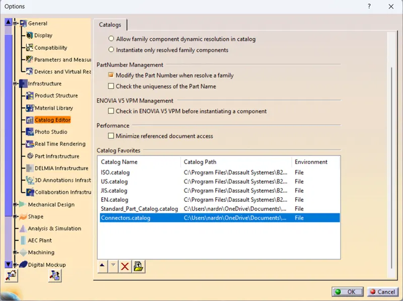
Then catalogue is created by Option --> Infrastructure --> Catalog Editor. In catalog favourites click add favorities then select required catalog which is shown below.
PROCESS OF WIRING HARNESS DESIGN:
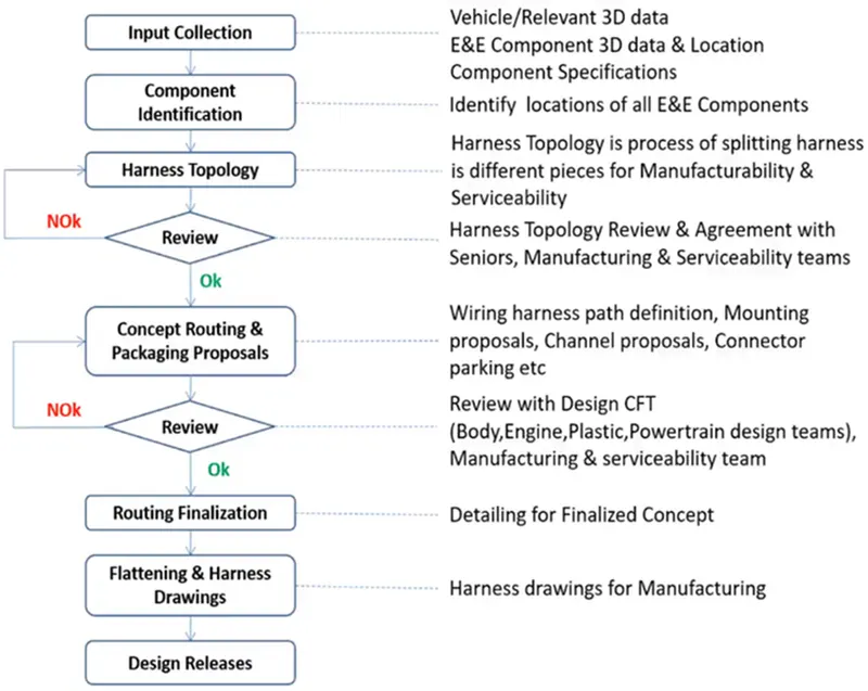
GIVEN PARTS FOR WIRING HARNESS:
- Deutsch DT06 – 08SA ( https://www.te.com/usa-en/product-DT06-08SA.html)
- Tyco 174357-2 (https://www.te.com/usa-en/product-2-174357-2.html?source=header-match)
- Tyco 85229-1 – (https://www.te.com/usa-en/product-85229-1.html?q=85229&source=header)
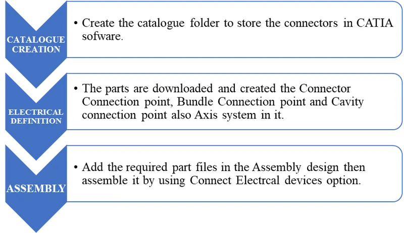
For designing the wiring harness all the parts are defined with their respective points in it and also for Assemble.
FLOW CHART OF WIRING HARNESS ASSEMBLY:
CONNECTOR DEFINITION:
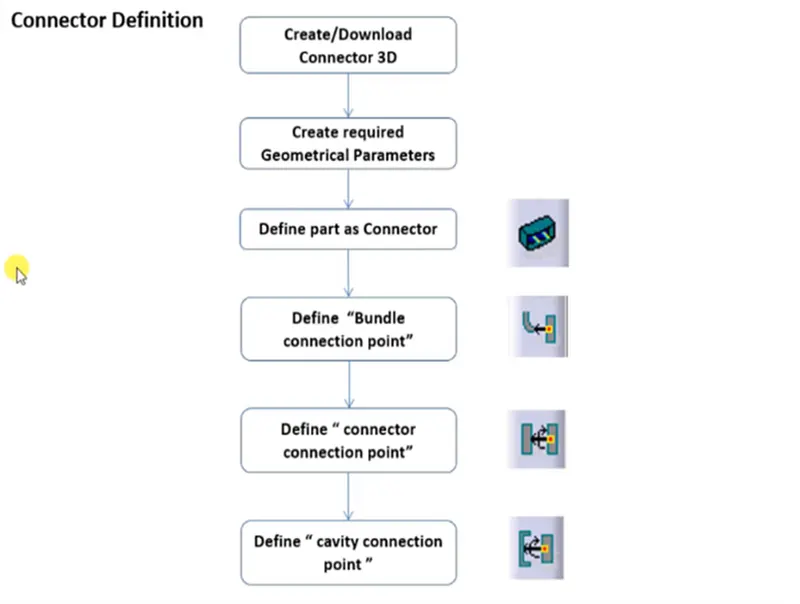
All the points are created by made point in centre and Axis system. In the axis system the axis is in desired position shown in below.
- X-axis: Towards the locking side
- Y-axis: Towards the connection
- Z-axis: left or right or other of the connector.
POINTS IN ASSEMBLE:
- CONNECTOR CONNECTION POINT -This point is used for the connection of one connector to another connector.
- BUNNDLE CONNECTION POINT - This point defines where the harness bundle segment point will end when routed to the electrical connector.
- CAVITY CONNECTION POINT - This point is used to define the connection of a connector to a connector clip. This only applies to connectors which have the mounting feature for a connector clip.
CONNECTOR 1 (Deutsch DT06 – 08SA):
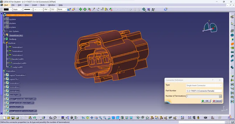
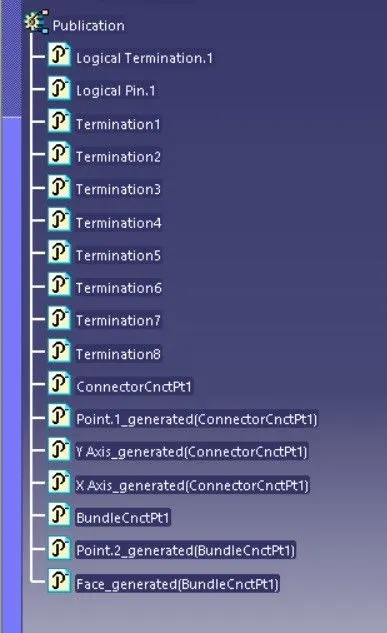
Initially points are created in the centre place of two faces and axis system is made in connector point by above axis consideration. By Define connector option select the part for wiring harness and enter number of terminations the part become electrical component which shown below.
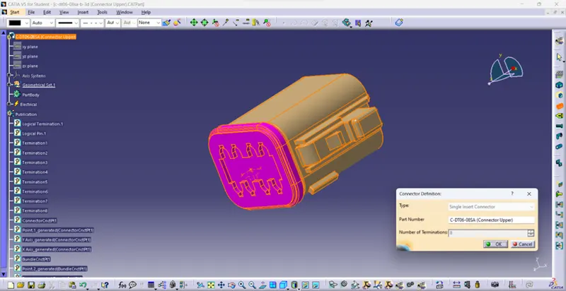
By select the Connector connection point click the faces, point and axis which shown below to make the connector connection point definition.
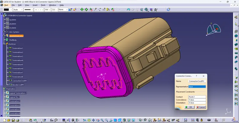
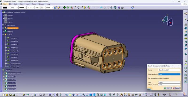
As same as bundle connection point definition is made by selecting face and points which shown below.
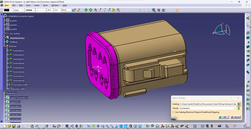
By clicking Store device icon select the part and in Catalog tab select the catalog path which above created and in Family tab select the connector as shown below.
CONNECTOR 2 (Tyco 174357-2):
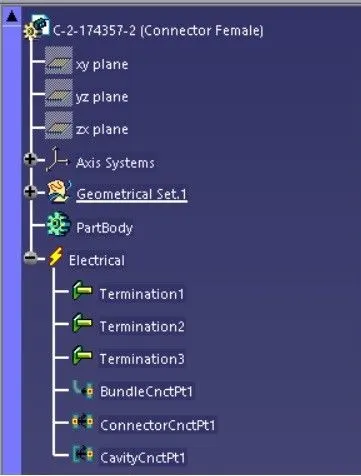
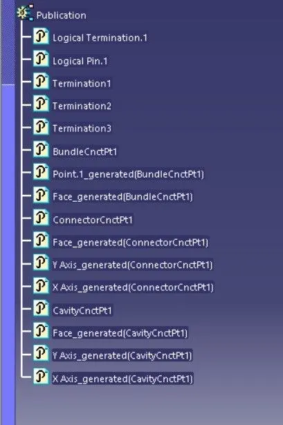
As same as the connector 1 here connector connection point and bundle connection points definitions are done by same steps followed in connection 1 which shown below.
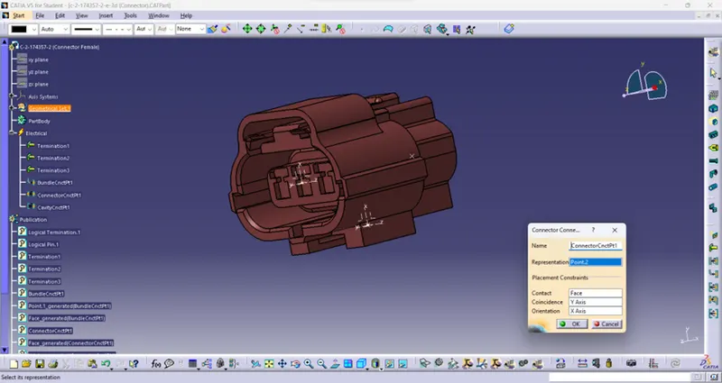
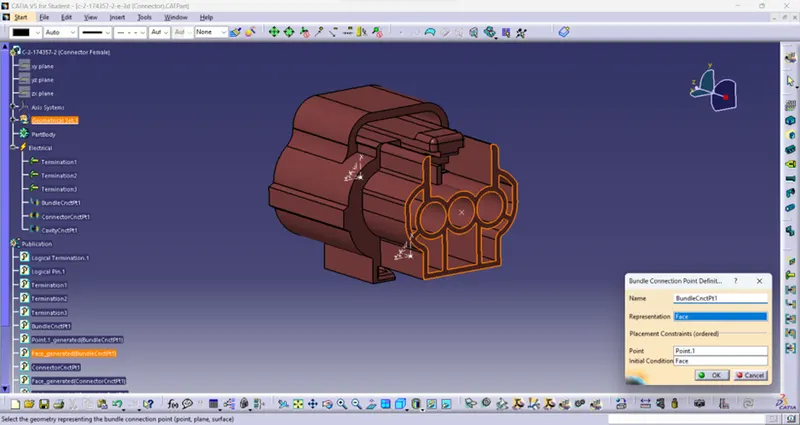
Here Cavity connection point definition is also done for assembly is shown below.
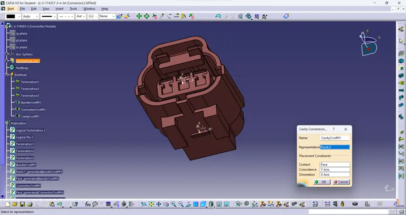
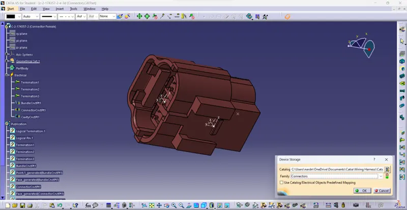
By clicking Store device icon select the part and in Catalog tab select the catalog path which above created and in Family tab select the connector as shown below.
CONNECTOR 3 (Tyco 85229-1):
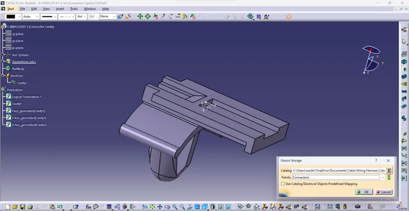
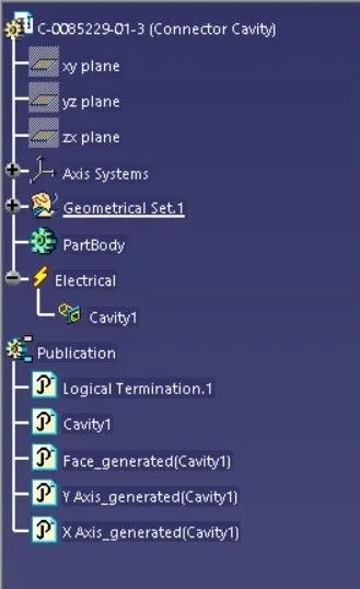
Above cavity connection point definition steps are done in this connector. In this connector this point only created.
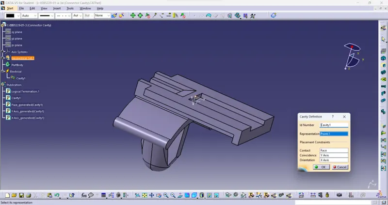
By clicking Store device icon select the part and in Catalog tab select the catalog path which above created and in Family tab select the connector as shown below.
ASSEMBLY:
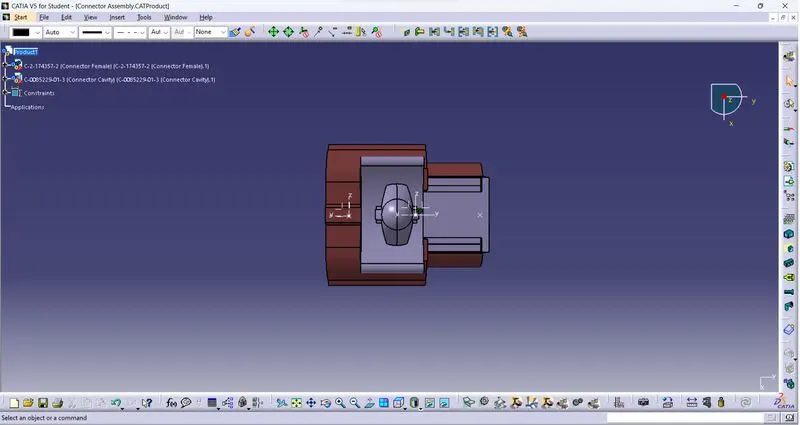
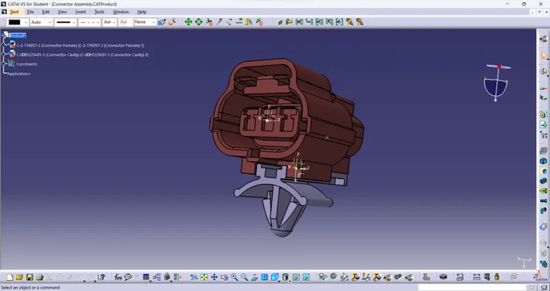
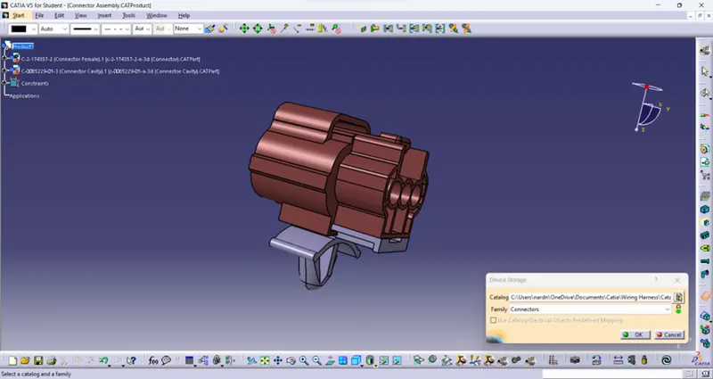
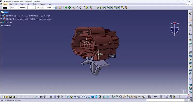
Here two parts are assembled (Tyco 174357-2 and Tyco 85229-1). Initially open the electrical assemble section and insert these two parts. They have already joint points so far assemble those parts click the Connect electrical devices icon and select those parts. After assemble Constraint symbols are visible in the parts.
Checked whether it is correctly assembled are not. If not then select Disconnect electrical parts and alter the position of parts for perfect assemble. Then assemble it by Connect electrical part icon.
By clicking Store device icon select the part and in Catalog tab select the catalog path which above created and in Family tab select the connector as shown below.
CONCLUSION:
From given parts Wiring harness and assemble are done by Catalogue creation and Electrical definition in the parts.
Connector 1:
Feautre tree 1:
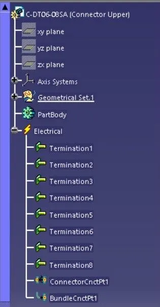
Feautre tree 2:
Connector 2:
Feautre tree 1:
Feautre tree 2:
Connector 3:
Feautre tree 1:
Isometric view:
Front view:
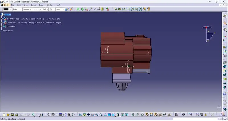
Side view:
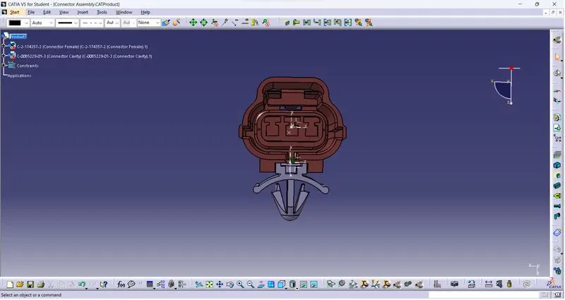
Top view:
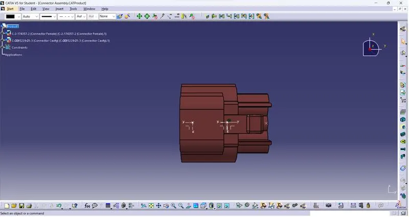
Bottom view: