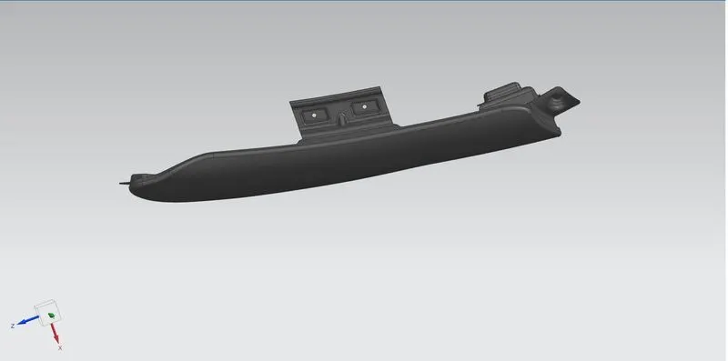
Fender Design
FENDER DESIGN
AIM:
To Design the Fender by given skin surface including their necessary mounting by considering given master section.
DESIGN METHODOLOGY:
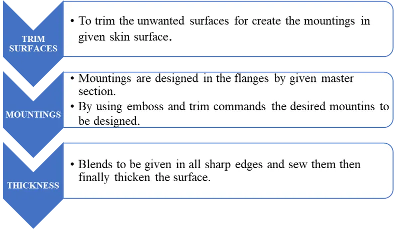
INTRODUCTION:
Fender is an aesthetic component/part of a car that frames the wheels. Prevention of sand, mud particles, and other road contaminants from being thrown into the engine compartment and also to the pedestrians by the rotating tires are the main purpose served by the fenders. The front fenders are separate components whereas the rear fenders are integrated with the body sides.
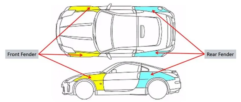
TYPES OF FENDERS:
- Full bumper types
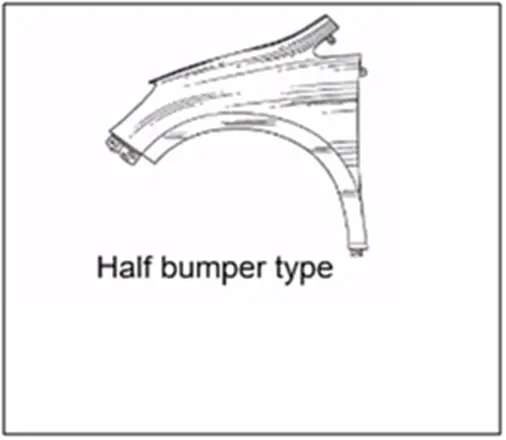
- Half bumper types
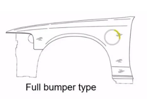
FULL BUMPER TYPE:
The full bumper type fender was used in old cars, it covers the full area until the front lighting. But it has a lot of sheet metal which is unnecessary and increases the weight of the fender. These type fenders are no longer used in the automobiles.
HALF BUMPER TYPE:
In this type the Fender covers half the bumper. It is widely used in nowadays to reduce the cost of metal used.
DESIGN OF FENDER:
There are 5 necessary mountings in the fender.
- Drip Area Mounting
- A-Pillar Mounting
- Sill Mounting
- Bumper Mounting
- Baffle Mounting
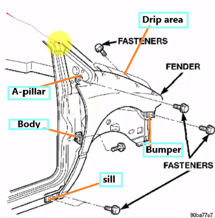
All the mountings in the fender are connected in the vehicle by fasteners by the holes in it.
Initially by given face the tangent edges are offset into 5mm in the surface and trimmed the unwanted surface by curve on surface in tangent condition to make 6 flanges in the skin.
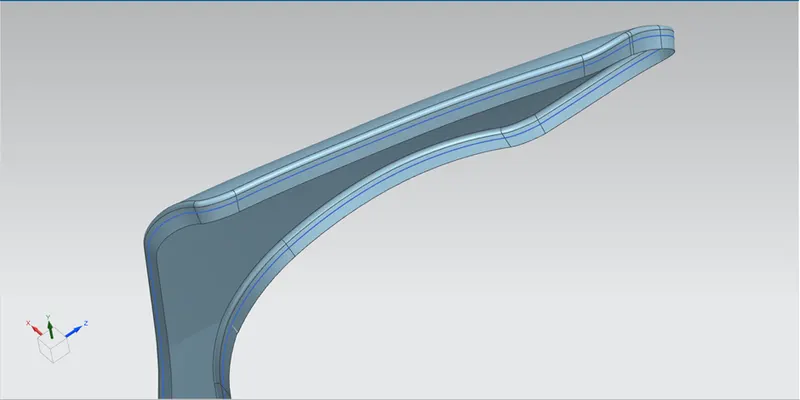
DRIP AREA MOUNTING:
The drip area is the most important mounting in a fender, it is the point where the fender has to be attached to the engine compartment. The drip area should be designed in such a way that it should be at least 150mm away from the front end of the fender to have sufficient space for mounting headlamps housing. Mostly the drip area starts from 200mm away from the rear end of the fender, to have sufficient space for the cowl which carries the wiper equipment. The length of the drip area depends on the length of the fender.
Below diagram shows the design consideration of the Drip are mounting.
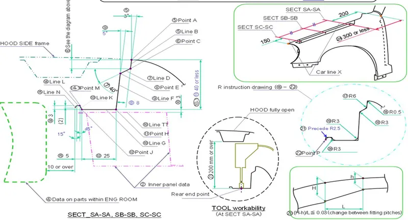
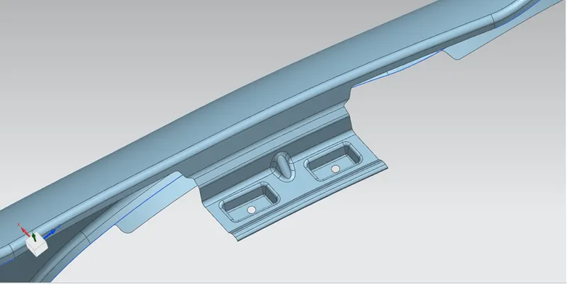
From the flange by using law extension command the drip area surfaces are created with distance and some angle condition. In the centre surface having 25mm datum plane is creates and two rectangles are drawn and project it in the surface.
By using emboss command the surfaces are embosses and two circles are projected in the surface and trimmed. Then all the edges are blended by given values. Finally, the dart is designed to strengthen the surface in the middle of two embossed surfaces. The resultant drip area is shown below.
A-PILLAR MOUNTING:
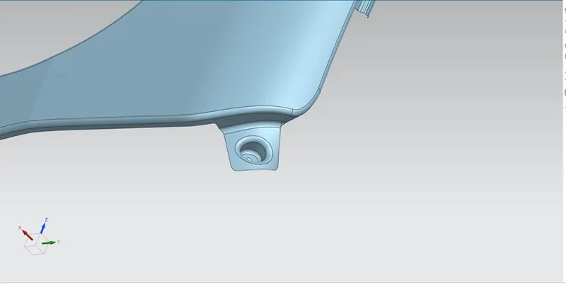
This mounting is connected to the A pillar in the car. Here the required flange is extended by the law of extension and trim slightly to make the plane surface. Then the datum plane is created and sketch is drawn which is in circular shape and project in the surface. The curve is embossed in the surface, here the circular shape is designed because it is curve surface. In the bottom of embossed surface circle is projected and trimmed for fastening. The corner edges are blended and trimmed the sharp corner by bridge curve in tangent condition.
The resultant A-Pillar Mounting is shown below.
SILL MOUNTING:
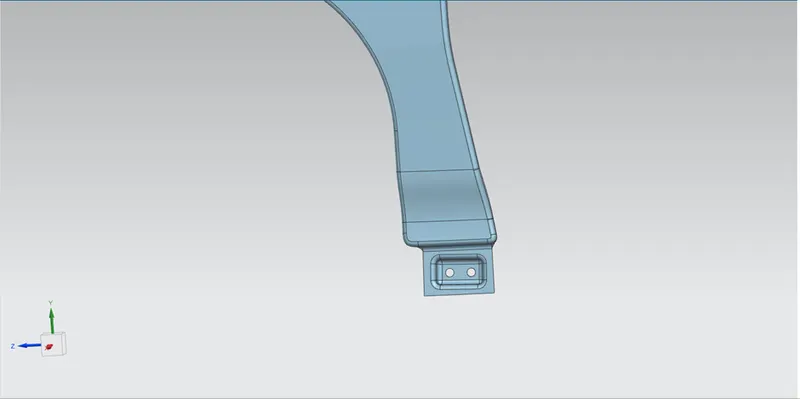
This mounting is in the bottom of the fender. In the flange the surface is extended by using law of extension in 900. Then the datum plane is created and drawn the sketch which is rectangular shape and project it in the surface.
The projected sketch is embossed in the surface and trim the circular shape by projecting in bottom of the surface to fastening. The sharp edges are blended and the resultant Sill Mounting is shown below.
BUMPER MOUNTING:
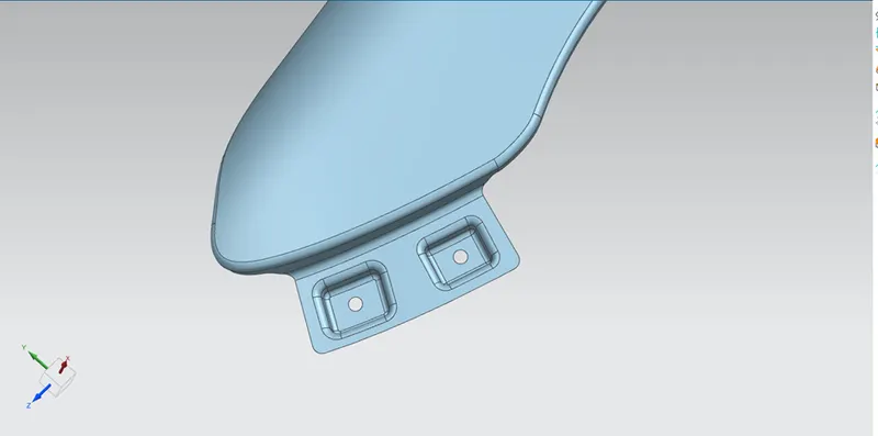
Bumper mounting is connected in the bumper section in the car. Bumper flange is extended by using law of extension with 900. Then the datum plane in created in the surface and drawn the sketch having 2 rectangle and project in the surface.
The two rectangles are embossed in the surface and circular shape is trimmed in the bottom of embossed surface by projecting circle shape in it for fastening operation. Then the edged are blended and resultant Bumper mounting is shown below.
BAFFLE MOUNTING:
Baffle mounting is connected in the wheel arc area here the push pin type is used for connecting also there is no need for strength in the surface. So, emboss is not used in this mounting and only the hole is required for fastening.
In this fender there is 2 baffle mountings are designed. Both flanges for baffle mounting have to create the datum plane and sketch is drawn which circle shape. Then project in their surfaces and trimmed. The resultant baffle mountings are shown below.
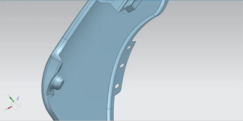
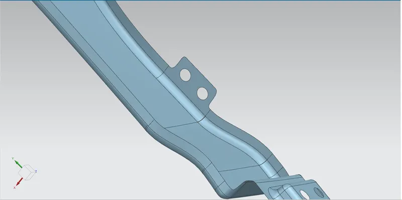
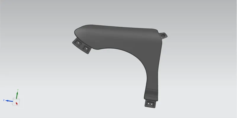
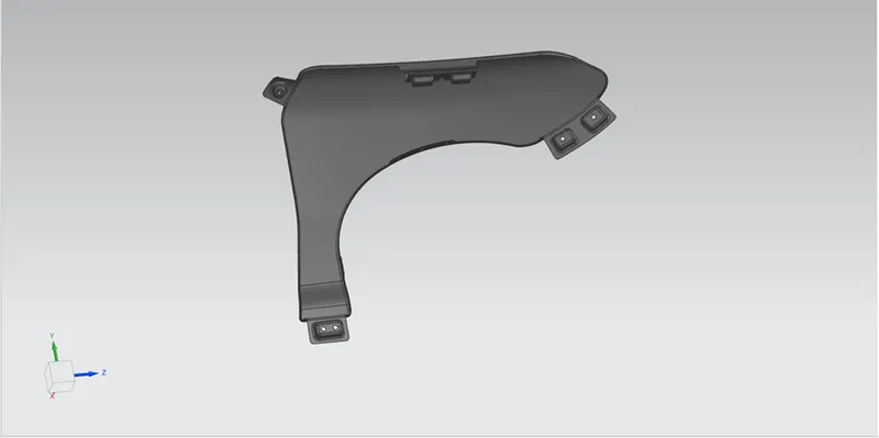
By creating all the mounting, the final fender surface is shown below.
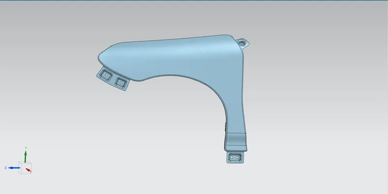
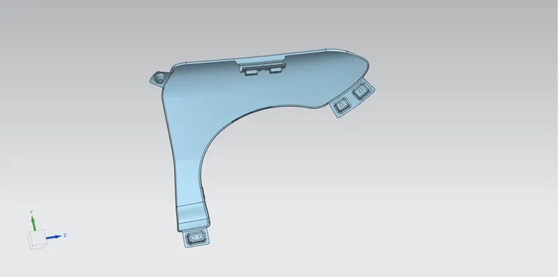
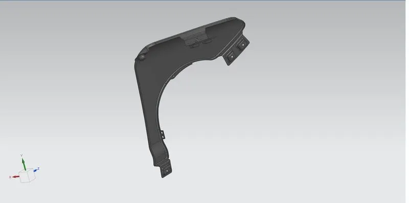
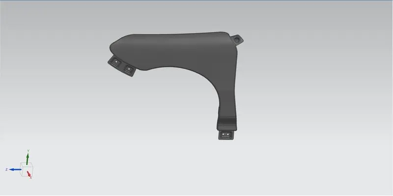
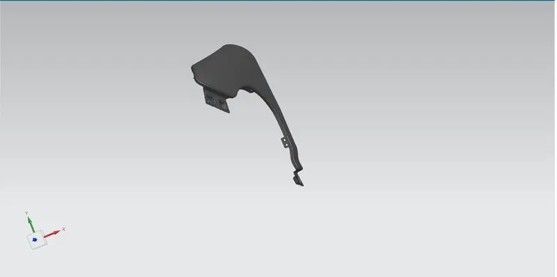
Then sewing all the surfaces, it is thickened in 0.75mm by thickness command. The final fender part is shown below.
CONCLUSION:
Thus the Fender part is designed by given skin surface and master section with required mountings.
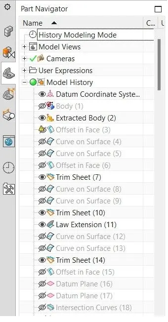
Feature tree 1:
Feature tree 2:
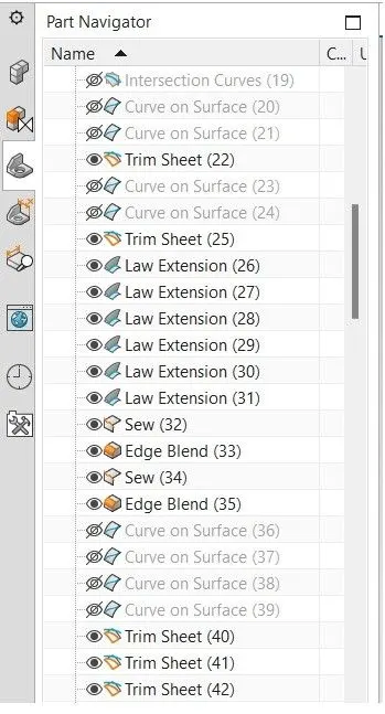
Feature tree 3:
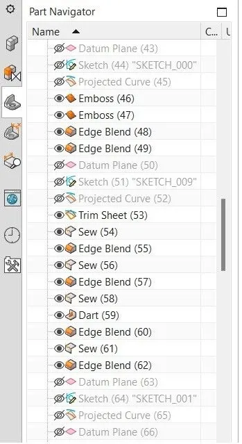
Feature tree 4:
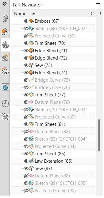
Feature tree 5:
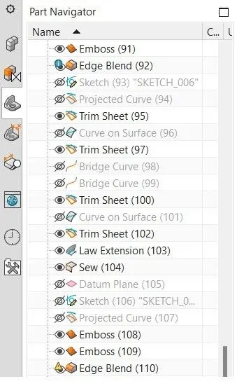
Feature tree 6:
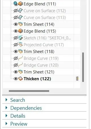
Isometric view:
Front view:
Side view:
Top view: