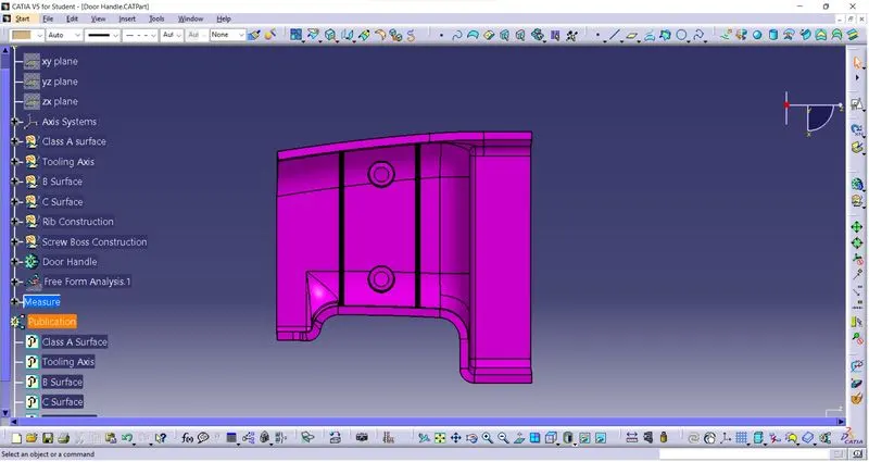
Week 9 - Attachment Feature Creation (Ribs & Screw Boss) - Challenge 1
DOOR HANDLE WITH RIB AND SCREW BOSS CHALLENGE - 1
OBJECTIVE:
To create the B, C surface from given Class A surface and design Rib and Screw Boss in Door Handle.
DESIGN METHODOLOOGY/APPROACH:
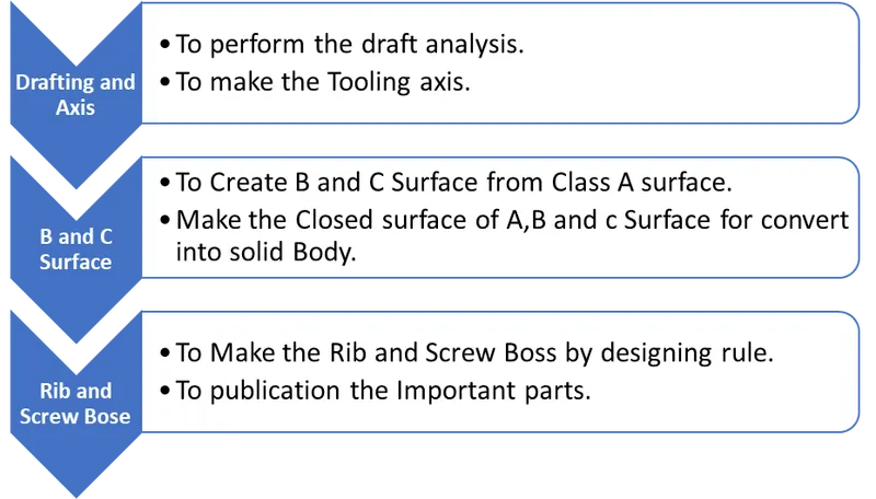
Draft Analysis:
Draft analysis is the analysis to examine whether the designed part is exit from the mould smoothly or not. Generally, 3 degrees from the Class A surface to be drafted. In the below diagram draft analysis is performed by given Class A surface.
Draft Analysis of Class A:
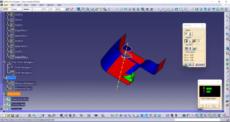
Draft analysis of Door Handle component:
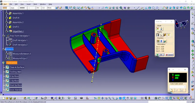
Tooling axis:
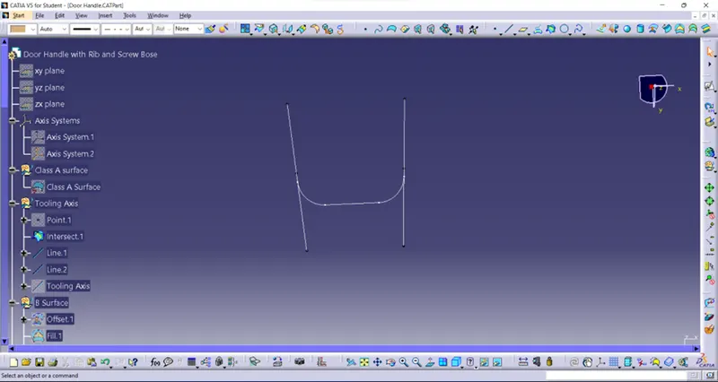
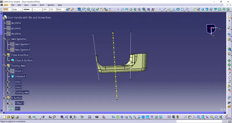
Axis which drafts the part from certain angle is called tooling axis. Initially the part is checked in all direction for tooling axis, the suitable direction for tooling to be selected considering reduce the mould cost. In this part considering all axis X axis is best for tooling. But there is Axis system is insert in the base surface with point create the line which is parallel to X axis, then using of intersect command intersect the given class A surface draw the line from centre with angle and made the bisecting line by created two lines. Finally, the tooling axis line by using bisecting line and points.
The drawn tooling axis is shown below.
Making of B,C Surfaces:
B Surface:
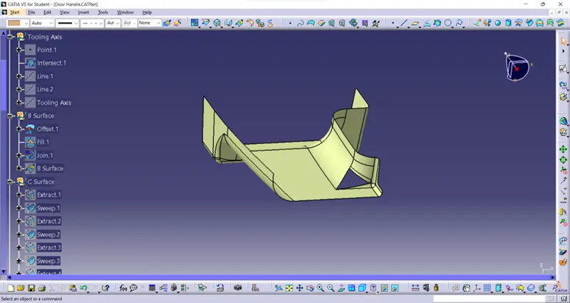
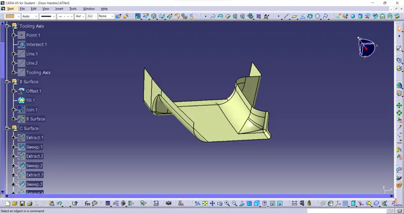
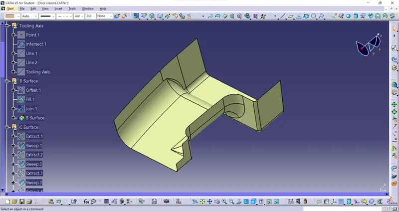
B Surface is made by offset the Class A Surface by 3mm thickness, then fill the gap and join it. Then extrapolate the surface for trim. The following images shown the steps for B surface.
C Surface:
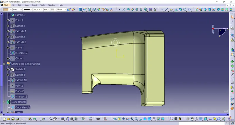
C Surface is made by extracting the boundaries of class A surface individually and sweep them by 3 degrees, then fill the gap and added.
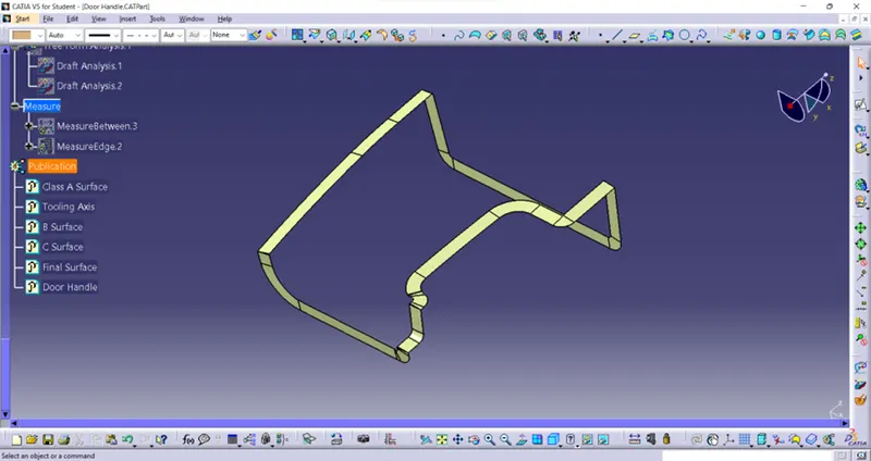
Then added it with A Surface. Finally trimmed it with B Surface to get final surface.
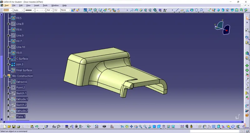
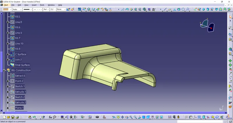
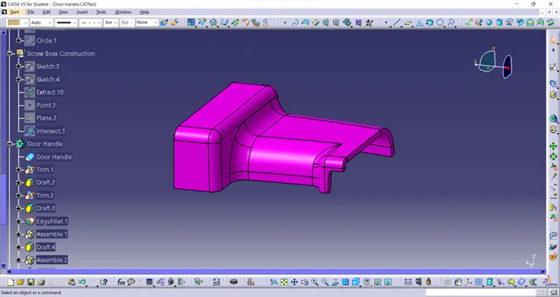
Adding body to define it and make them closed surface to make them solid body.
Making of Rib and Screw Boss:
Rib:
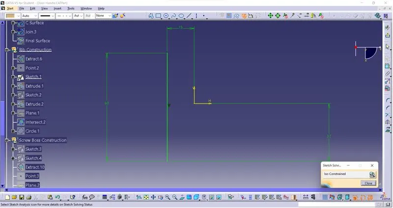
Initially extract the base surface and draw a line which is shown in figure.
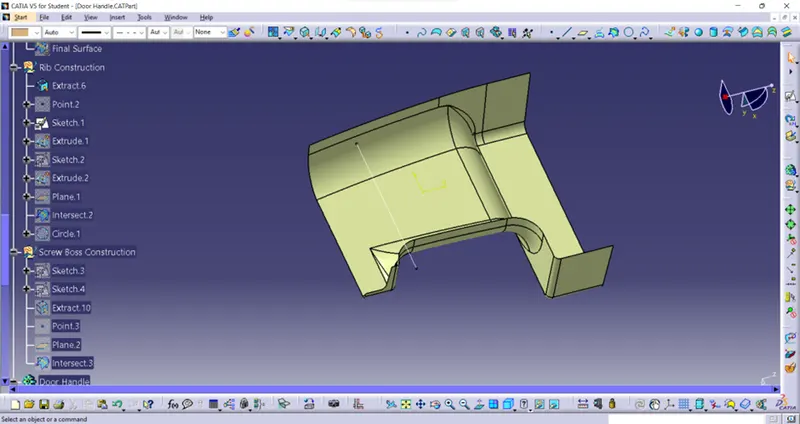
The line is extruded by 15mm (5t = 5*3 = 15) and made into thickness of 1.2mm (0.4t = 0.4*3 = 1.2) by adding body which definite it.
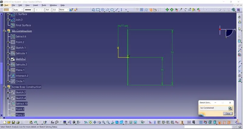
As same as for next rib the above step is repeated. Then the two bodies are added into final part by Untrim operation to remove unwanted faces.
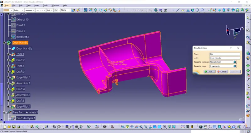
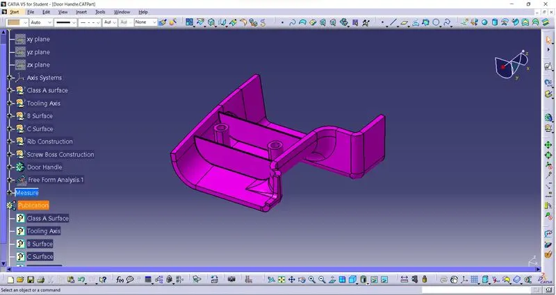
The door handle having two ribs are shown in below image.
Screw Boss:
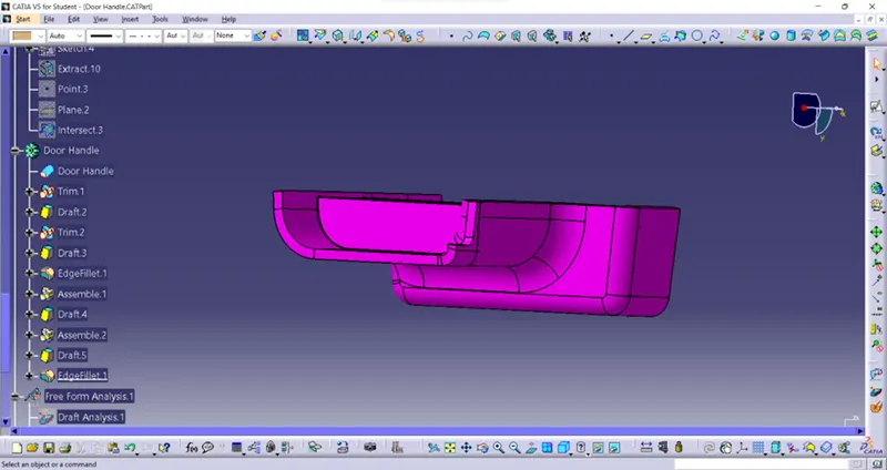
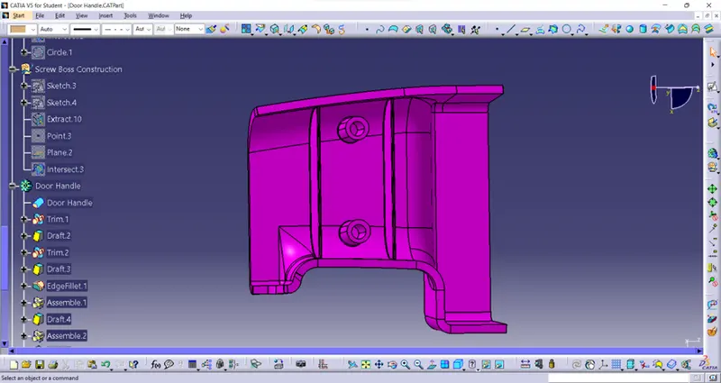
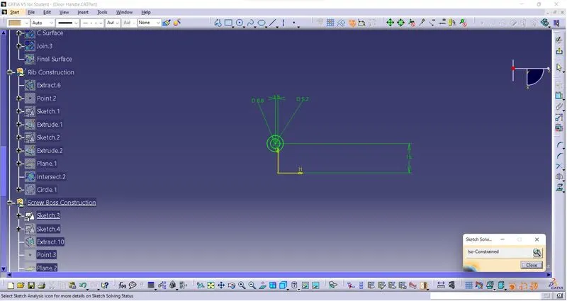
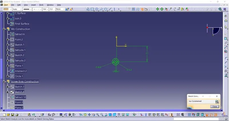
For screw design the two circle is drawn by considering M6 Screw the inner diameter is 5.2mm and outer diameter is 8.8mm (0.6t for one side = 0.6*3 = 1.8 for one side then for two side 3.6 then added into inner diameter 5.2+3.6=8.8).
Then the sketch is extruded into 15mm. For the next screw Boss before step is repeated by changing sketch dimensions. The below images shown the steps taken to make the screw Boss.
Drafting and fillet:
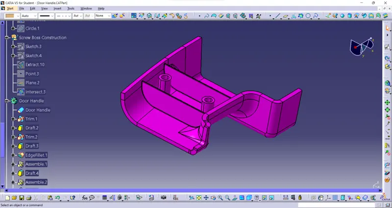
Both Rib and Screw Boss are drafted by 0.5 degree for easily eject from mould.
And fillet is done for both the value is 0.5mm. so the door handle with rib and screw is shown below.
Intersection:
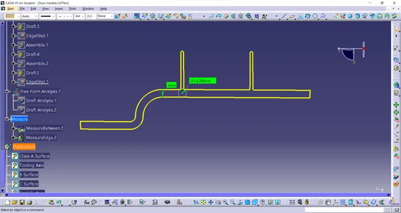
By intersecting the part in required side is useful for examine the part having ribs and Screw Bose are made by designing rule. The below images shown the intersection for both Ribs and Screw Boss.
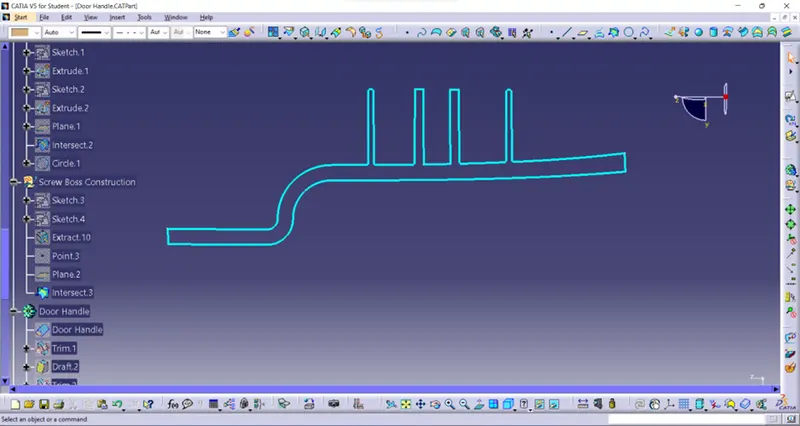
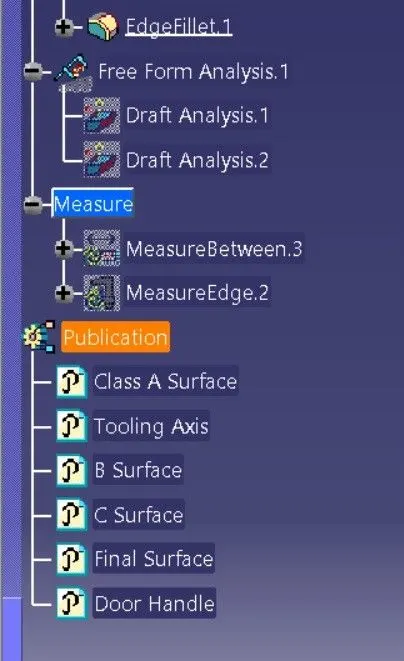
Finally published the Tooling axis, A, B, C Surface, Final Surface and Door Handle.
Conclusion:
By using above methods Door handle with Ribs and Screw Boss are made.
Sketch 1 fully defined:
Sketch 2 fully defined:
Sketch 3 fully defined:
Sketch 4 fully defined:
Expanded tree structure 1:
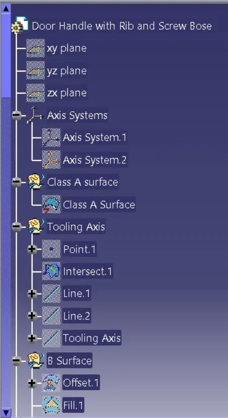
Expanded tree structure 2:
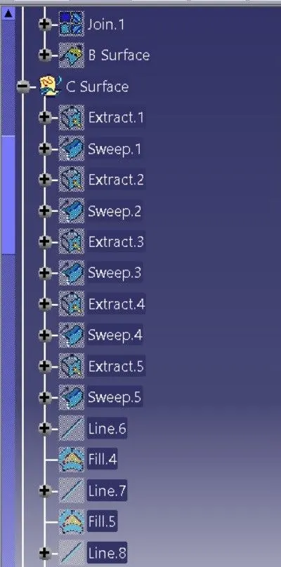
Expanded tree structure 3:
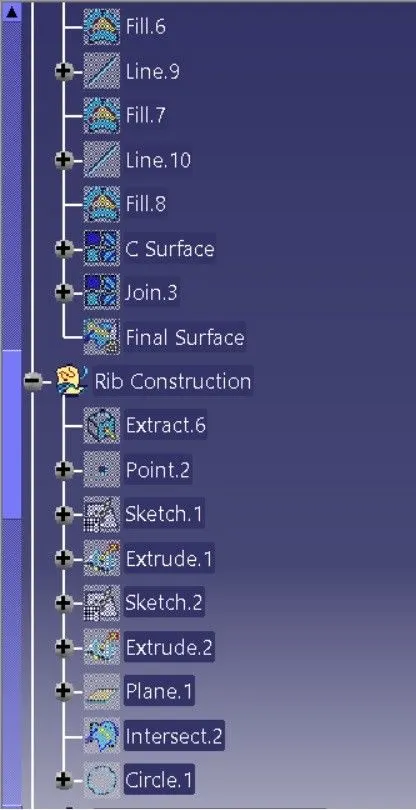
Expanded tree structure 4:
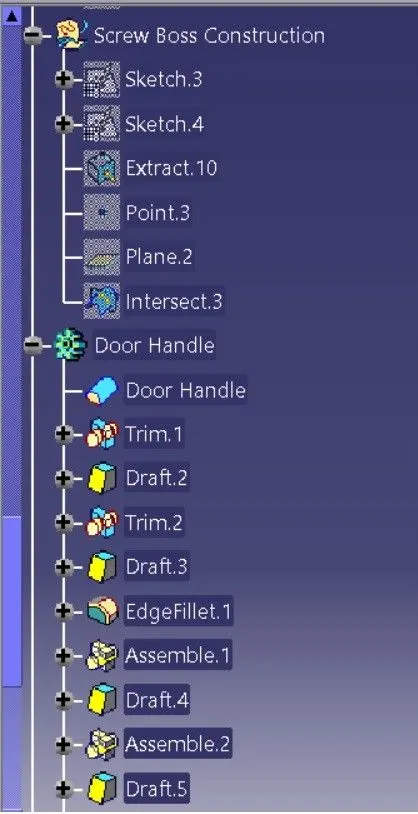
Expanded tree structure 5:
Isometric view:
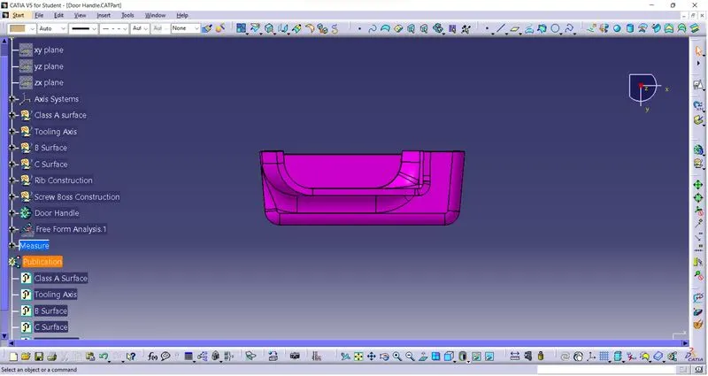
Front view:
Side view:
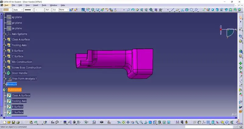
Top view: