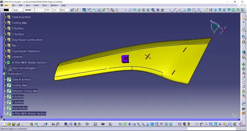
Week 9 - Project - A pillar Design with Master Section
A PILLAR DESIGH WITH MASTER SECTION, PROJECT
OBJECTIVE:
To create the Pillar design Master section through the given Class-A surface and design Locator, Dog House and rib in the part.
DESIGN METHODOLOOGY/APPROACH:
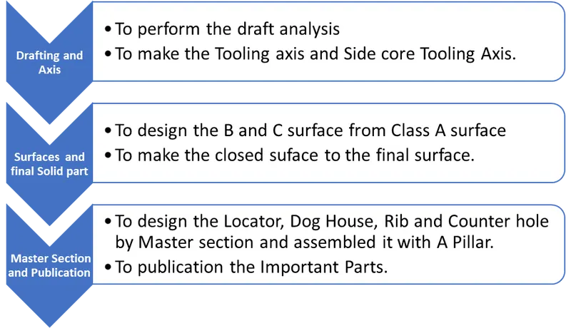
Draft Analysis:
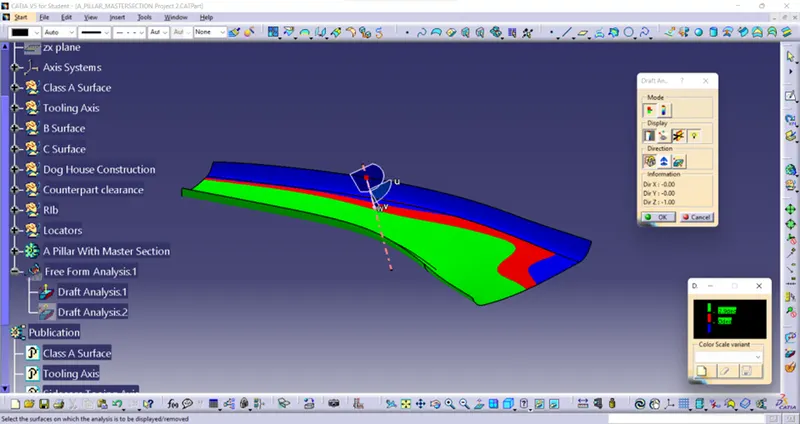
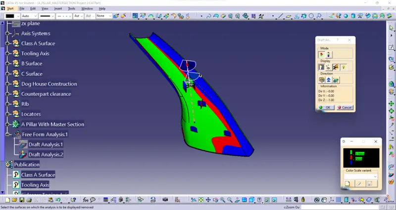
Draft analysis is the analysis to examine whether the designed part is exit from the mould smoothly or not. Generally, 3 degrees from the Class A surface to be drafted. In the below diagram draft analysis is performed by given Class A surface.
Draft Analysis of Class A:
Draft analysis of final part:
Tooling axis:
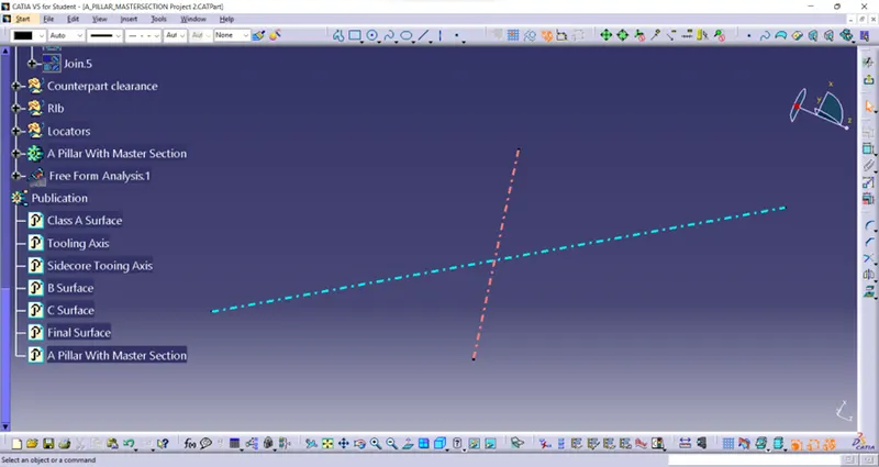
Axis which drafts the part from certain angle is called tooling axis. Initially the part is checked in all direction for tooling axis, the suitable direction for tooling to be selected considering reduce the mould cost. In this part considering XY axis there is no disturbing surfaces so by given curve of class A surface draw the lines as shown in figure.
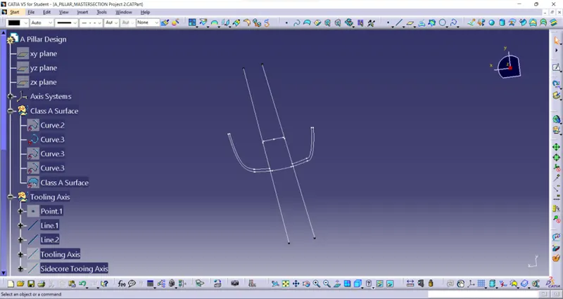
By using bisecting line command add these two lines and make the bisecting line, that line is Tooling axis.
The drawn tooling axis is shown below.
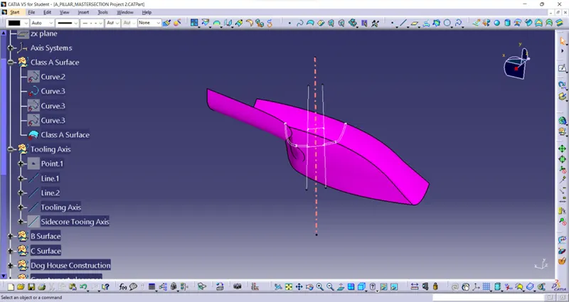
B Surface:
Offset and Corrected Surface:
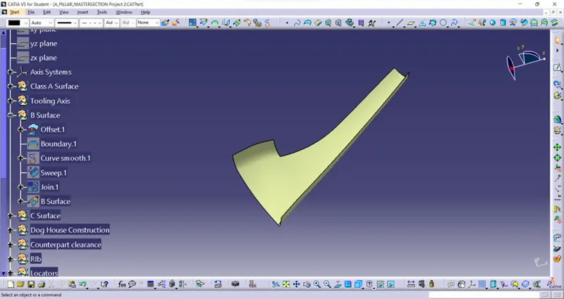
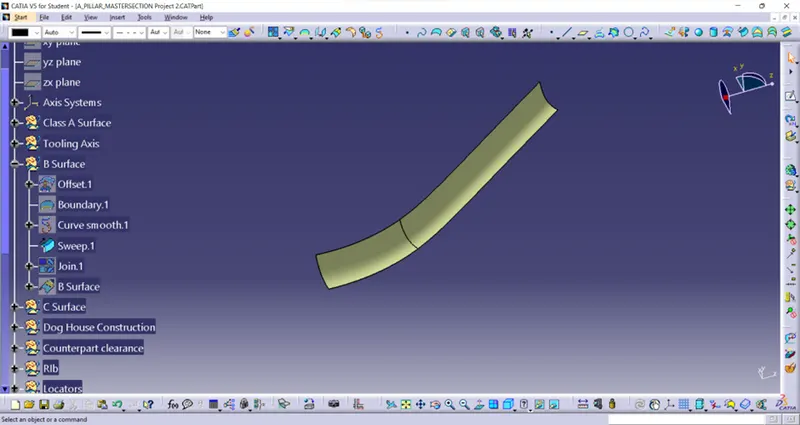
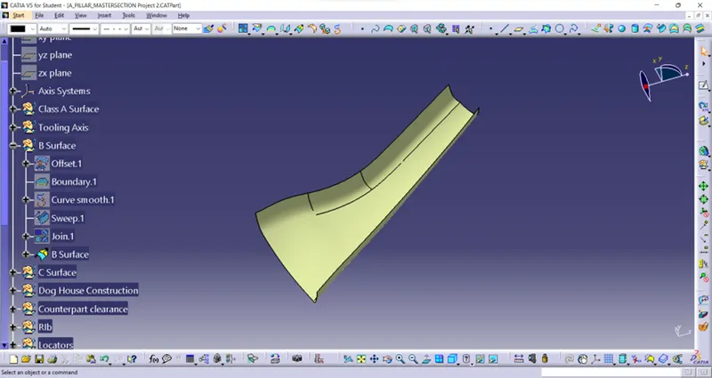
In this model class A surface is offset in 2.5mm for thickness. However, the surface has some errors such gap between the surface. By Boundary command extract one of the gap edge made it into Smooth curve and Sweep it with another edge of surface, Join it and Extrapolate in some distance to make the B Surface. The following image are shown how the making of B surface.
Offset surfaces:
Corrected surfaces:
B Surface:
C Surface:
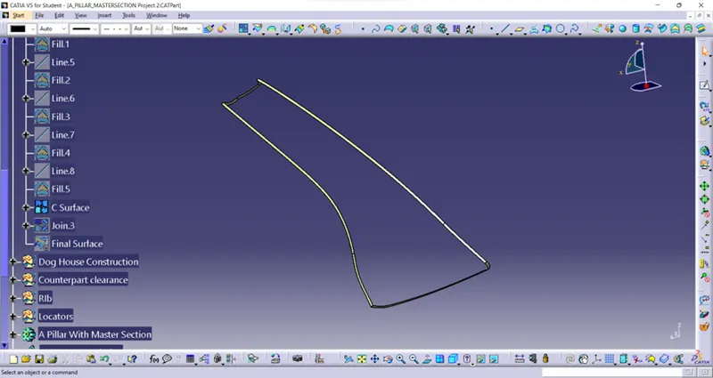
Surface which connects the A surface and B surface is called C surface. It is done by make the extract and Multiple extract in the Class A surface like boundary surface. The surface is individually extracted and sweep with reference surface at an angle 93 degree and 5mm length and trimmed with B surfaces. So, the C surfaces are automatically joined with B surface. In every corner there is a small gap is occurred by using fill command and fill it. The following images shown the design of C surface.
Final part:
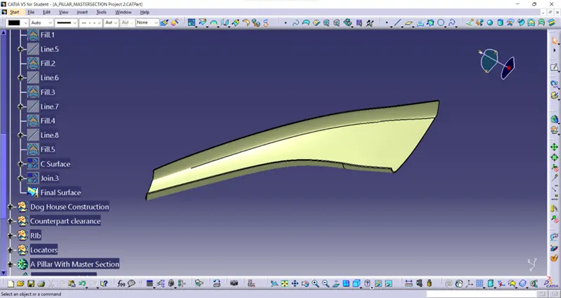
After sweep there is a gap between them so they are extrapolating and trimmed to merge the gaps. The final C surface, A surface and B Surface are Join. The final part is shown below.
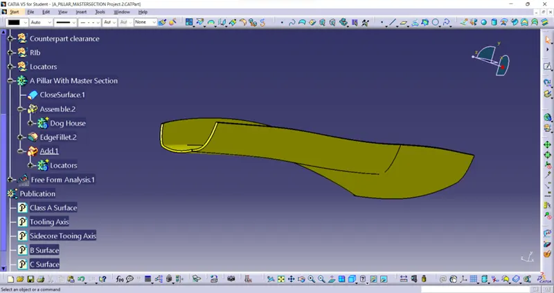
And define the part body then the surface is made into solid body by using Closed surfaces which is shown in below.
MASTER SECTION:
Design of Dog House, Rib Counter Hole Clearance and Locator:
Dog House:
Initially Extract the B surface and create plane which is tangent to surface and drawn the sketch for Dog house then extrude it with 30mm and the extruded surface with rotate to desired position. The open surface is closed and join it.
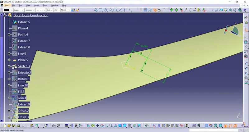
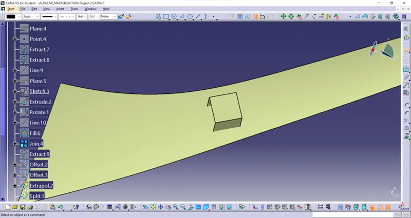
The line is drawn perpendicular of Tooling Axis for the side core Tooling Axis
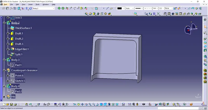
By adding body as defined thicken the surface with 2mm then draft the outside face with 1.5 degree. Fillet of 3mm added and extract the inside face with tangent continuity and offset it 1mm and also offset the extract surface in 4mm. the offset surfaces are trimmed to get side core cut surface.
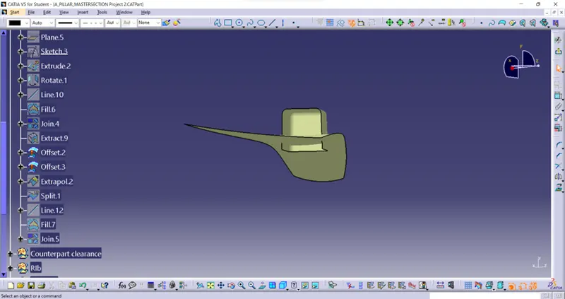
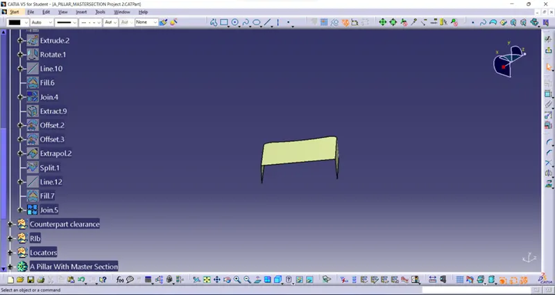
The Drafted part is again drafted in inside faces by side core tooling axis in 0.5 degree. Then by Split command split the part by cut surface. The resultant Dog house is shown below.
Rib:
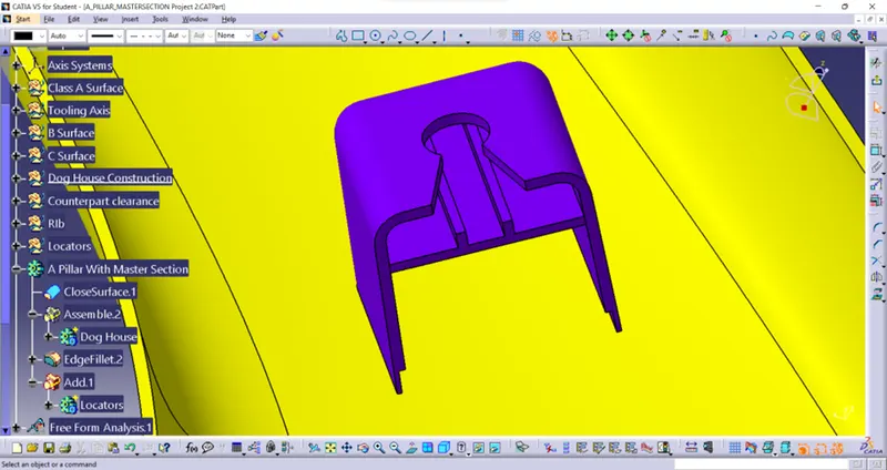
By considering backside face the sketch is drawn to create the rib. By adding body as defined it the sketch is padded 30mm with thicken.
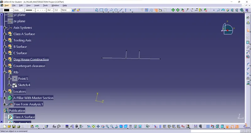
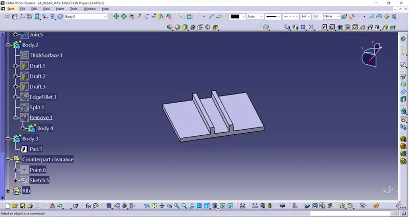
Then the body is assembled with the dog house body.
Counter hole Clearance:
By considering top surface of dog house the sketch is drawn and adding body as defined Pad the sketch. Then the body is inserted into dog house body by remove option.
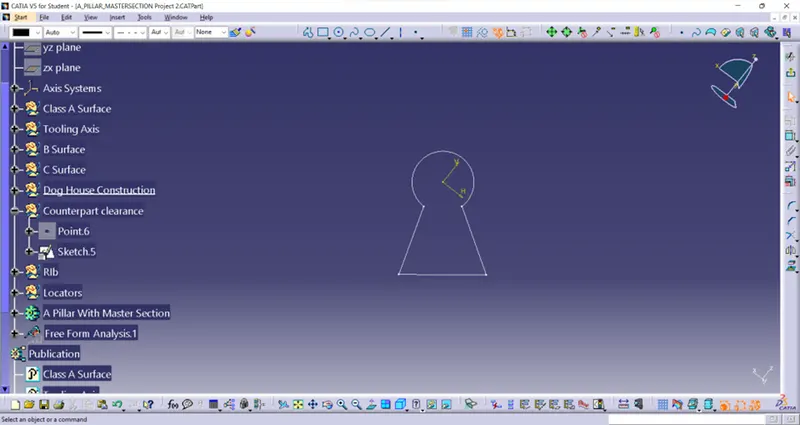
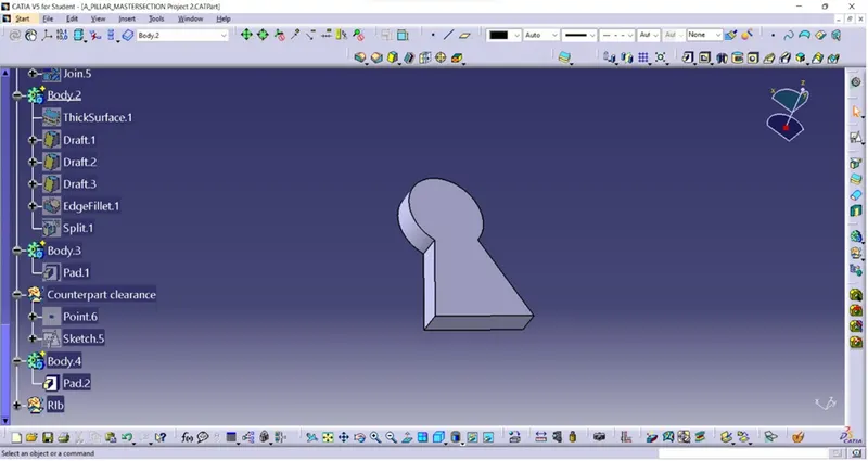
Then the body is added into A Pillar body, the resultant dog house body with Rib and Counter hole is shown below.
Locator:
Initially create the three points to design 2 way and 4-way locator. And the sketches are drawn shown in below.
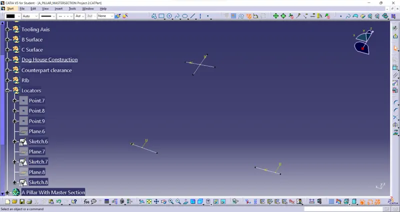
Then it Padded by insert body option as thickness with 1.5mm and height 20mm, drafted in 0.5 degree. Then chamfer in four edge and given fillet in edges. The locators are shown below.
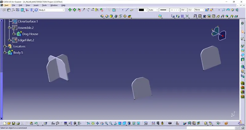
Then the locator body is assembled into the A Pillar body.
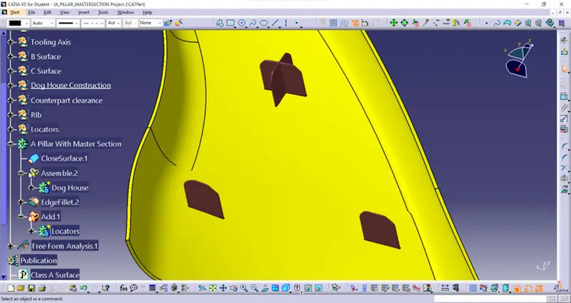
The final A Pillar with Master section is shown below.
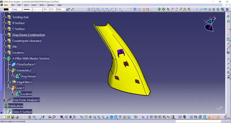
Then the Class A surface, Tooling axis, Side core Tooling Axis, Surface B, surface C, Final surface and Master Section is published in feature tree.
Conclusion:
So, by using above method B and c surfaces are made from Class A surface and Closed part is made. Then Master Section such as Dog House, Rib, Counter hole and locator are designed.
Sketch 1 fully defined sketch:
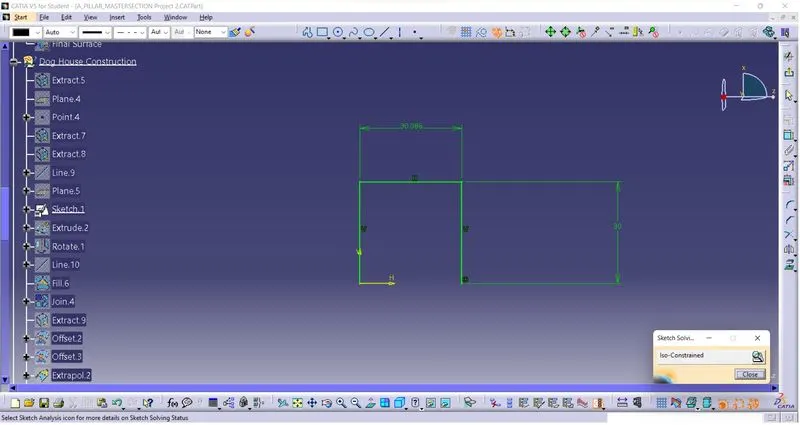
Sketch 2 fully defined sketch:
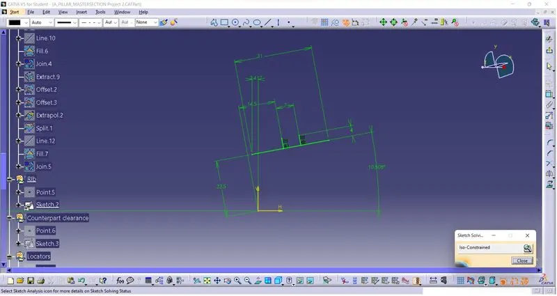
Sketch 3 fully defined sketch:
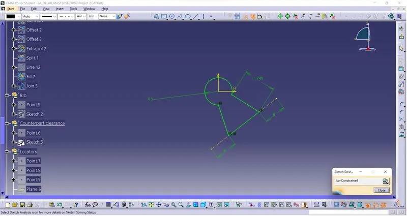
Sketch 4 fully defined sketch:
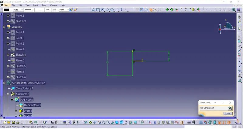
Sketch 5 fully defined sketch:
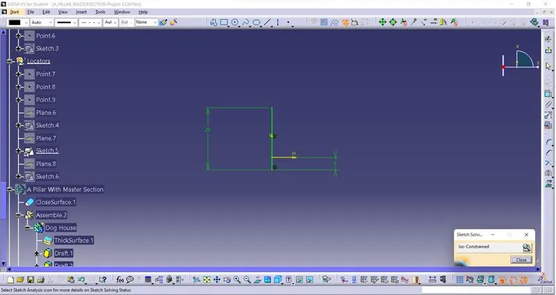
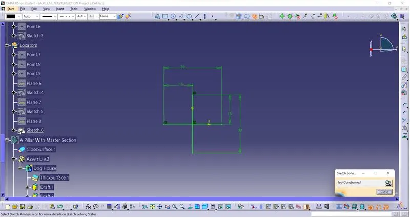
Sketch 6 fully defined sketch:
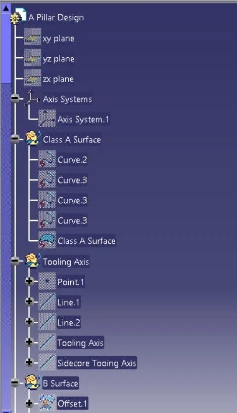
Expanded tree stree structure 1:
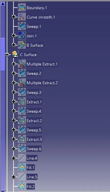
Expanded tree stree structure 2:
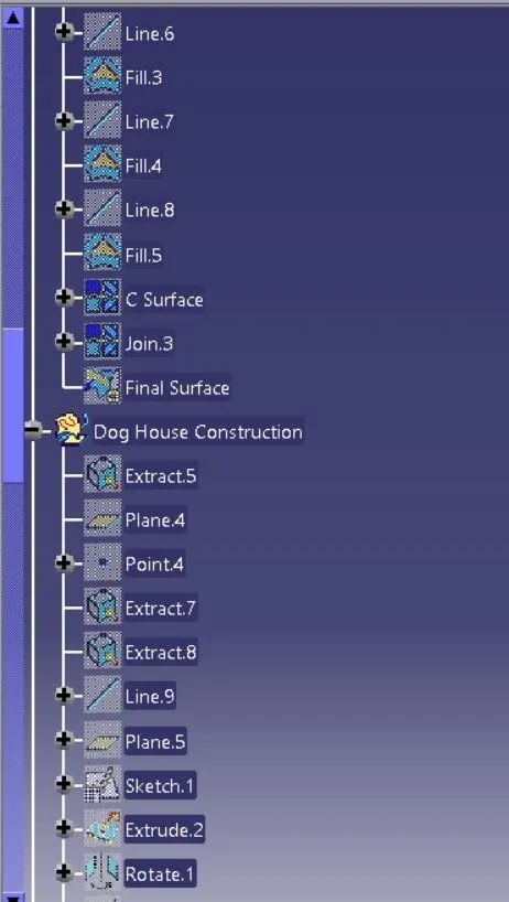
Expanded tree stree structure 3:
Expanded tree stree structure 4:
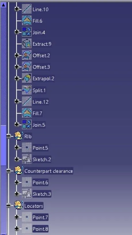
Expanded tree stree structure 5:
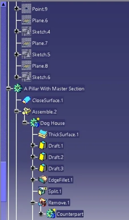
Expanded tree stree structure 6:
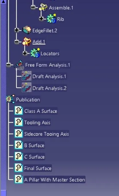
Isometric view:
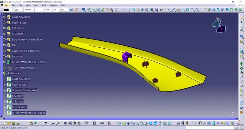
Front view:
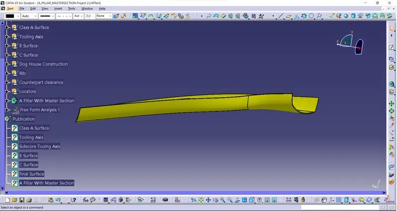
Side view:
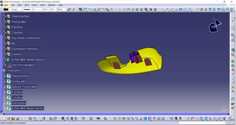
Top view: