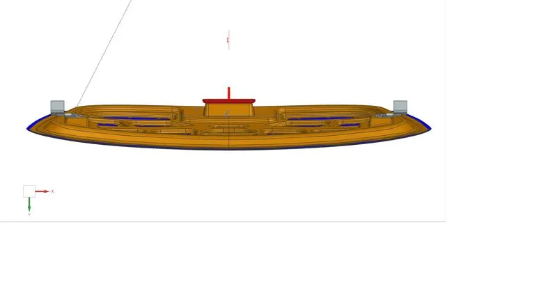
Hood design-Week 2
HOOD DESIGN
AIM:
To Design Hood Outer Panel, Inner Panel and the necessary reinforcements by following the Master Section mentioned with the Design parameters. Also assemble the parts to make the Hood.
INTRODUCTION:
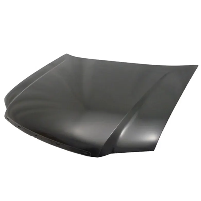
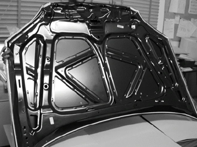
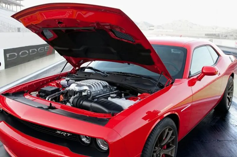
The hood or bonnet is the hinged cover over the engine of motor vehicles. Hoods can open to allow access to the engine compartment, or trunk on rear-engine and some mid-engine vehicles) for maintenance and repair. The top and view of Hood is shown below.
HOOD SUPPORT:
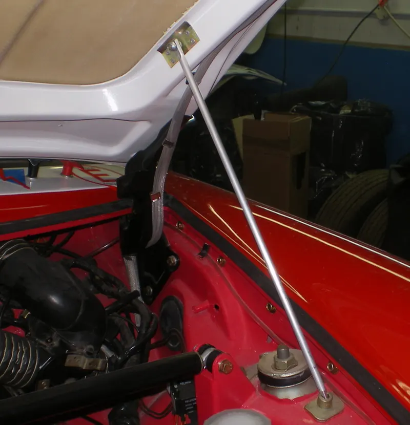
SUPPORT ROD:
A hood rod is designed to hold your hood propped open whenever you need to do some work in your car's engine bay. When used, it must be firmly secured to ensure that it provides a stable hold on the hood. Meanwhile, when not in use, it must be kept stable in place and must not move around. The hood rod clip is the part assigned with that function. This clip clamps onto the rod and ensures that it is firm in its place when not in use. It keeps the rod from moving around under the hood and from causing trouble.
GAS STAY:
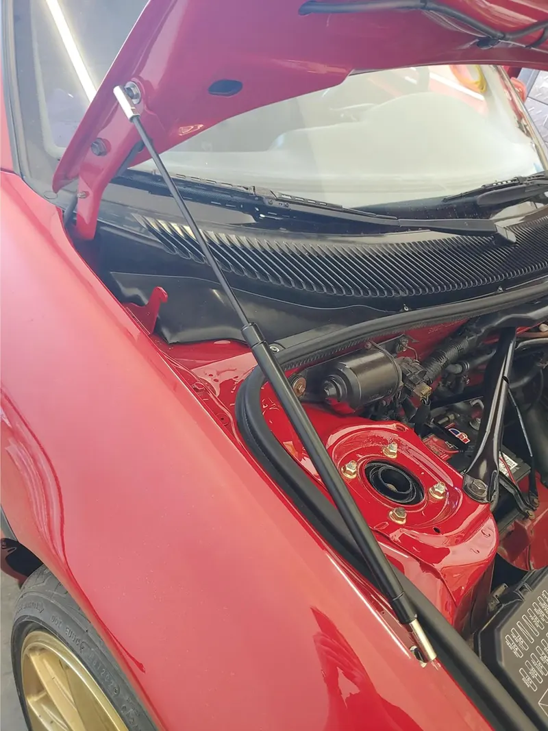
This is used to open the car hood by just providing little lift force. A small effort is all it needs and other work is done by gas pressure. It is normally found in high-end cars where the mass of hood is more than normal.
PARTS IN HOOD:
- Inner panel
- Outer panel
- Hinge
- Striker
DESIGN APPROACH:
MASTER SECTION DIAGRAM:
DEEP DRAWING:
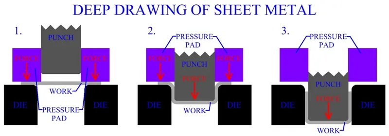
Deep drawing is a sheet metal forming process in which a sheet metal blank is radially drawn into a forming die by the mechanical action of punch. The molding process where by means of pressure and tensile stress a sheet metal blank is changed into a curved body.
SAFETY REQUIREMNETS:
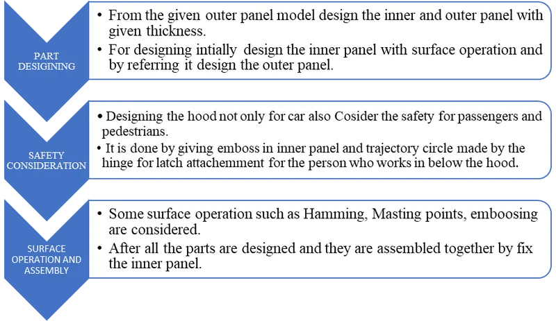
While designing the hood safety of the both passengers and pedestrians to be considered. More strength to the hood is give more strength to the vehicle and passengers. It is done by emboss in the inner panel of the hood for distribute the force away from car while crash.
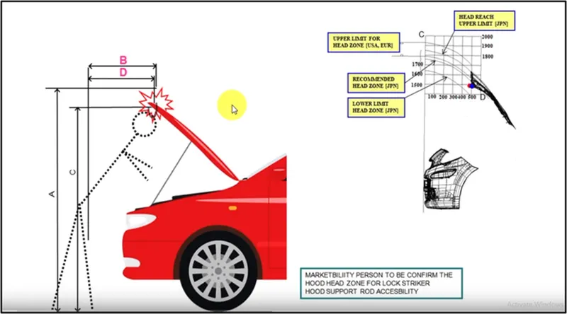
The opening height of the hood also to be consider in designing for the safety of the person who works in front section of vehicle such as engine, battery etc. There is an average height is calculated for the opening height of hood and it is varied by countries.
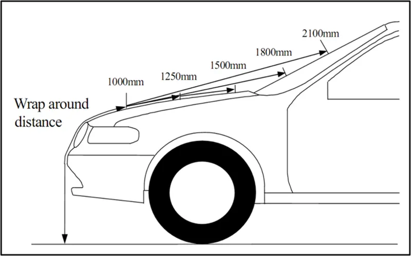
When a car crashes on the pedestrian, the whole human body wraps around the front shape of the car and the head impacts on the bonnet or the windscreen. The distance on which the head impacts on the car from the ground is called as the Wrap Around Distance (WAD). During the crash analysis, based on the Wrap Around Distance (WAD), two test areas will be created namely Child head impact zone and the adult head impact zone. The child head impact zone is between 1000 to 1700 mm WAD and the adult head impact zone ranges between 1700 to 2100 mm WAD.
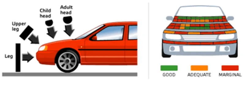
Below image shown the crash analysis and for design the hood the maximum green area should be provided for safety of pedestrians.
DESIGN OF HOOD:
DESIGN OF INNER PANEL:
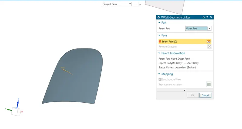
Initially the outer panel model is extracted in the part name as inner panel by using wave link geometry as shown below.
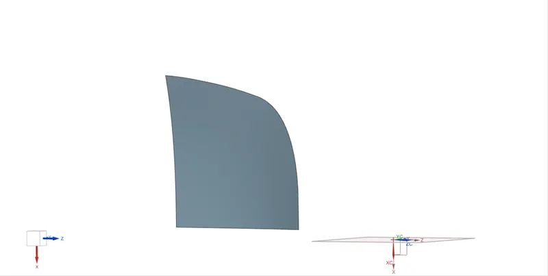
Then the surface is trimmed into half by using plane normal to the surface.
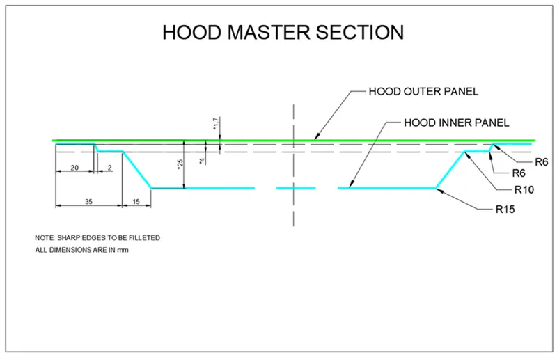
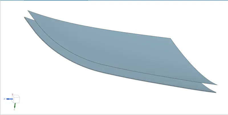
By considering the surface as parent surface offset the surface in 1.7 mm, 4 mm and 25 mm.
For the first offset surface draw arc by offset face command at 20mm inwards curve and trim the inside curve. The step is repeated at 22 mm and 35mm offset and keep the centre surface on the second offset surface. For third offset surface the above step is repeated at 50 mm and trim the outside surface. For offset face the fillet is given in the sharp corner.
Then the all three surfaces are joined by through surface command which is shown below.
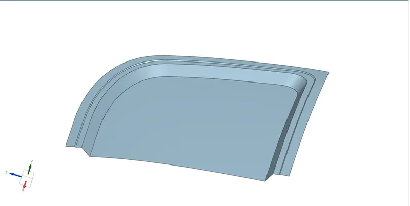
By using sew command sew the surfaces and given edge blend by the value given in Master section.
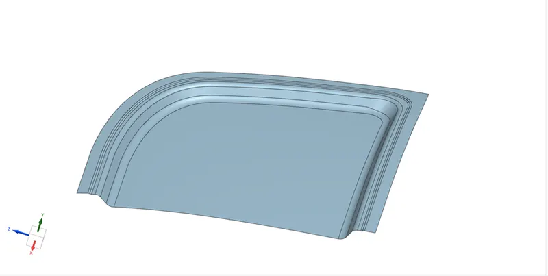
Then the bottom surface outer curve is projected and offset then sketch the curve for the gap of Strike and Hinge.
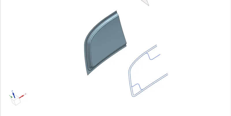
Then the sketch is projected on the surface and trim the unwanted lines and by using emboss command the surface is embossed by the offset distance is 10mm at 15 degree as the shape of given curves.
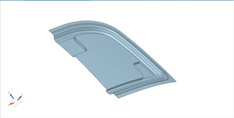
EMBOSS:
Embossing is a metal stamping process for producing raised or sunken designs or reliefs by passing metal sheet or strip between rolls of the desired pattern. The process enables repeated production without variation and does not change the metal’s wall thicknesses.
In sheet metal forming, the embossing technique can be used to strengthen sheet metal materials and to improve their properties. Increase in strength is achieved by strain hardening and residual stresses induced as a result of the embossing process, which locally influence the mechanical properties of the sheet metal blanks such as yield and tensile stress.
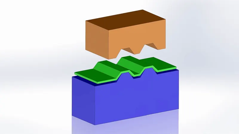
After embossed the surface is further project and drawn the sketch inside it then trimmed it to give some shapes for further emboss and project it.
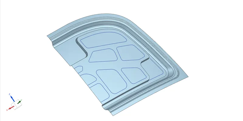
The curves are individually embossed by offset distance 8.5 mm at angle 15 degree and the edges are blended.
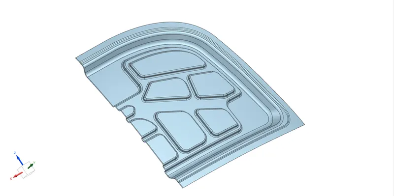
Generally, the mastic section (inner side of the outer panel and outer side of the inner panel which having thickness) is 5mm.
Here the total height = 25mm
Thickness of outer panel = 0.75mm
Thickness of inner panel = 0.75mm
Mastic section gap = 5mm
So, the total height of the both embosses is 18.5mm (as given in 10mm to first emboss and 8.5mm to second emboss).
The sketch is drawn by project the second emboss curve for trimming it by giving gap and mastic section circles.
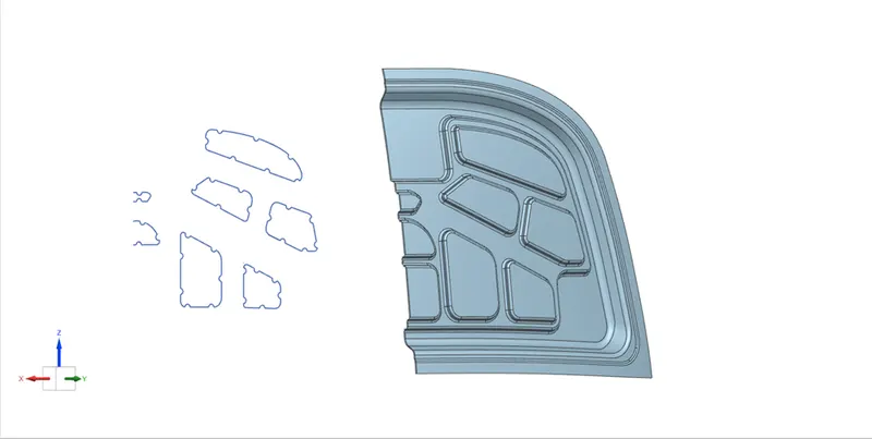
Then the sketch is projected in the second embossed surface and trimmed it by shown in figure for the mastic section.
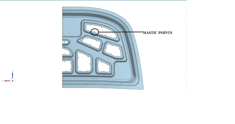
Mastic points:
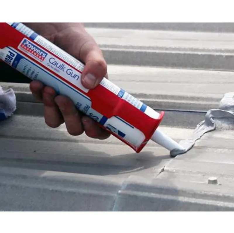
These are the spots where the inner panel and the outer panel of hood are joined or can say sealed together using a mastic glue. To fix the outer panel, if process like bolting, riveting or welding is used, it will lose all its aesthetics. So, mastic sealant is used which is elastic compound and acts like rubber. It is placed between both the panels. Initially it is in paste form and after hot furnace bath it gets solidify and gives strength to the panels together. One spot normally has influence over diameter of 80 mm.
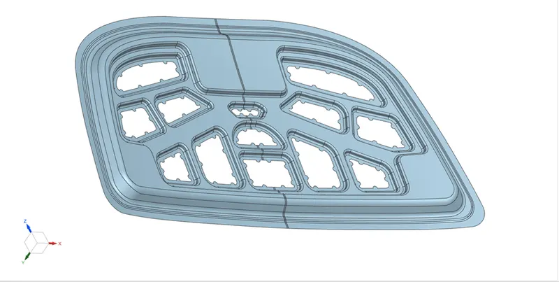
By offset face the outer curve is offset in some distance with fillet in sharp corner and trimmed it for smooth assemble.
The vertical surface is little bit extended by extend surface for fill the gap which trimmed by above operations and trimmed it by the plane normal to the surface. Then it is mirrored.
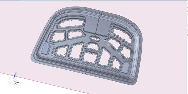
Plane is created which is parallel to the surface but some angle given to it to create the emboss for hinge assembly. By using the plane sketch is drawn and it is embossed reference of plane and mirror it.
By assembling the latch the hole is trimmed in the inner panel.
Latch Trajectory:
Then the hinges are assembled in their position the two points are created which is centre of axis of two hinges and the line is drawn between them. By using the created datum plane the circle is drawn and the centre point of circle and the midpoint of axis line is made coincident constrain.
The value of circle is adjusted for assemble the striker. Then the tangent line is drawn from the surface in the circle, here the circle is the trajectory path of striker.
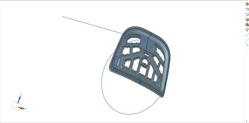
The striker is move towards the inner panel which is where the striker is assembled there is a little gap is ensured with striker and the inner panel. Then the backside surface is extracted by linked surface command.
By using law extension command the extract surface curve is extended with a degree toward surface depends upon the datum plane then trimmed the unwanted surfaces.
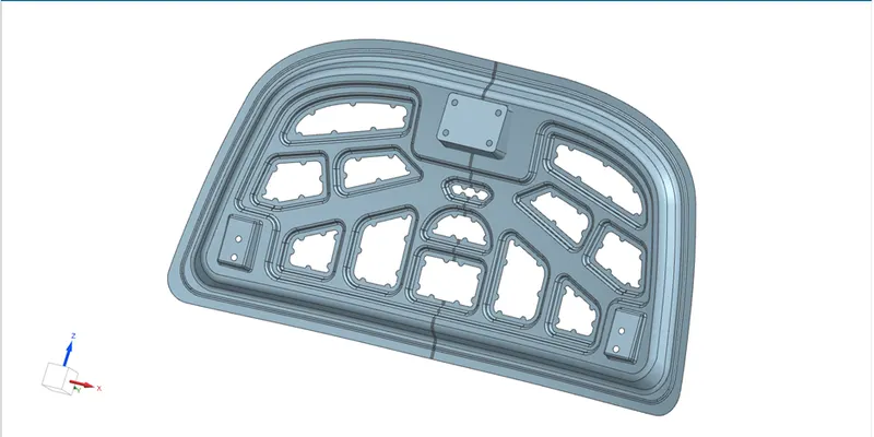
Then the surfaces are sewed and given edge blend this is the final surface of the inner panel.
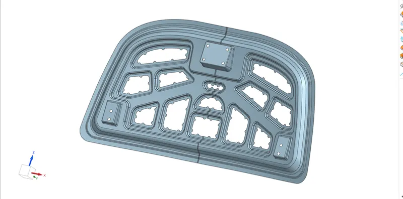
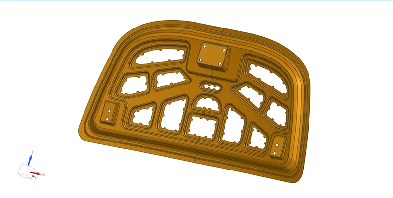
At last, the surfaces are given thickness of 0.75mm in the direction towards the outer panel.
DESIGN OF OUTER PANEL:
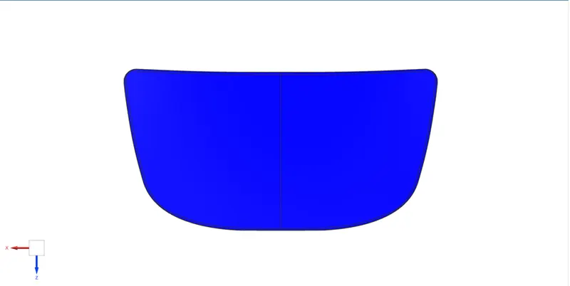
Initially the outer panel model is trimmed the other side by plane normal to surface.
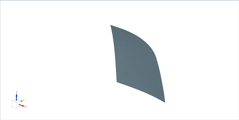
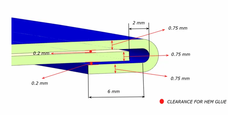
Then the surface is trimmed little bit by offset face by given fillet in corner. Then the face is offset by 2.65 mm (considering thickness of both inner and outer panel and hemming gap).
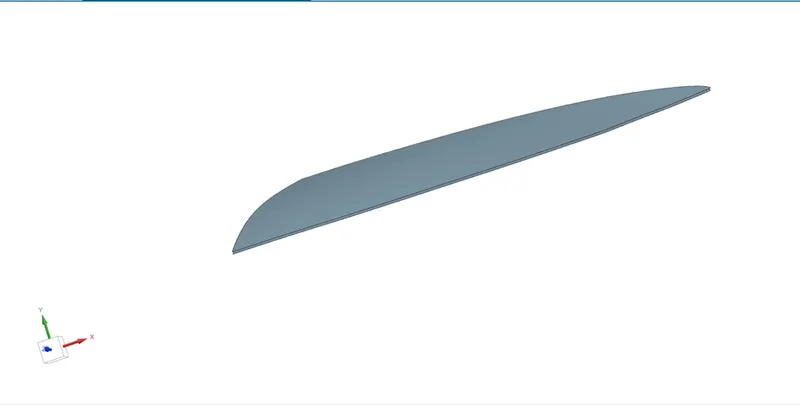
The offset surface is trimmed by offset in face command at 8mm remove the inner surface. By using through curve join the two surfaces then give edge blend by sew the surfaces.
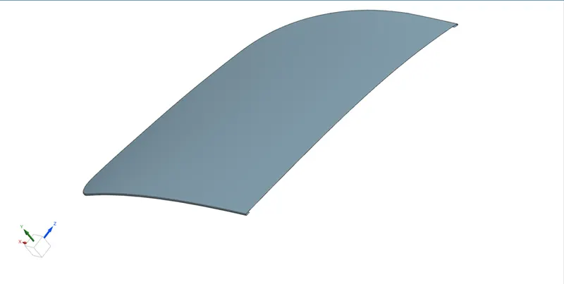
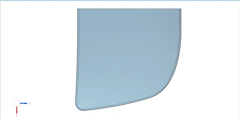
The curves are drawn on the corner to cut the surface for make the corner relief to the hemming process which is distance of 3mm.
Hemming:
Hemming is a forming operation in which the edges of the sheet are folded or folded over another part in order to achieve a tight fit. Normally hemming operations are used to connect parts together, to improve the appearance of a part and to reinforce part edges.
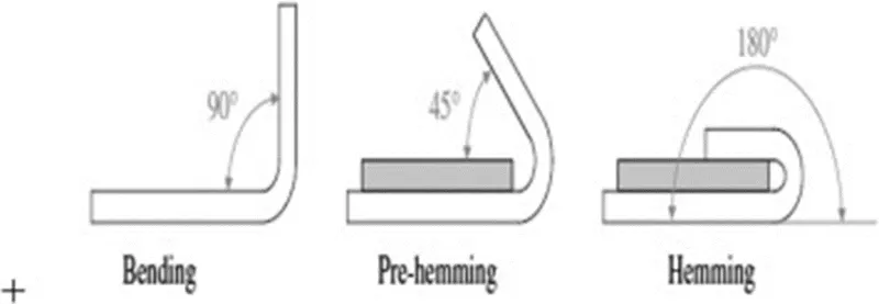
Then the surface is sewed and given edge blend. The surface is mirror to the normal plane have the final surface and given thickness of 0.75 mm inward direction.
ASSEMBLE:
By make inner panel as fix adjust the outer panel if required for the hemming which shown below.
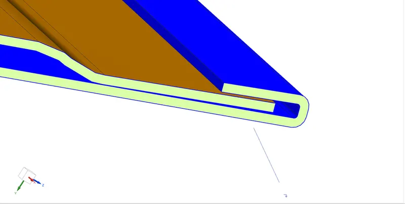
Already extract the backside face the striker is automatically attached to the inner panel.
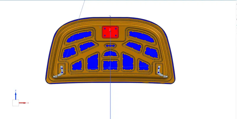
For hinge the emboss surfaces of inner panel and hinge face are given constrain parallel and touch.
Finally, the assembled are made to design the Hood.
CONCLUSION:
By above safety consideration, design approach the parts of the hood is designed and assembled. Thus, the Hood is designed in SIEMENS NX.
Inner panel feature tree 1:
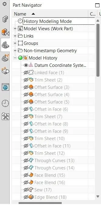
Inner panel feature tree 2:
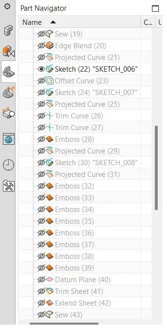
Inner panel feature tree 3:
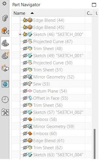
Inner panel feature tree 4:
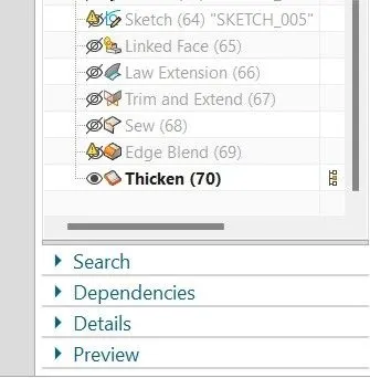
Outer panel feature tree 1:
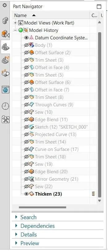
Assemble feature tree 1:
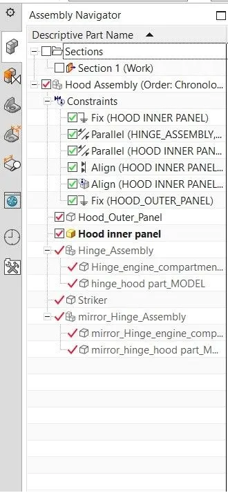
Isometric view:
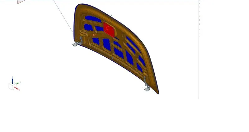
Front view:
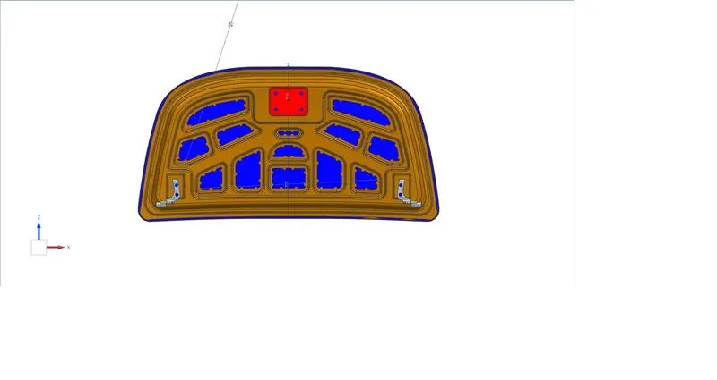
Side view:
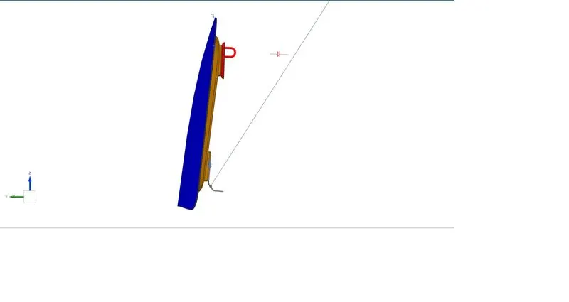
Top view:
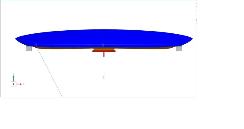
Bottom view: