Wiring harness routing & packaging Rules Week 3 Challenge
WIRING HARNESS ROUTING AND PACKAGING RULES WEEK 3 CHALLENGE
AIM:
To download the given CAD files defines it Electrical properties in CATIA Software workbench and also create the corrugated tubes in given dimensions by create the catalog in the Slit COT family.
QUESTION 1:
Download following cad data & define it as Electrical support using Electrical Part design Workbench. Define all the necessary properties.
P Clamp:
For define the Electrical properties in the given P Clamp the steps to be followed which is mentioned below.
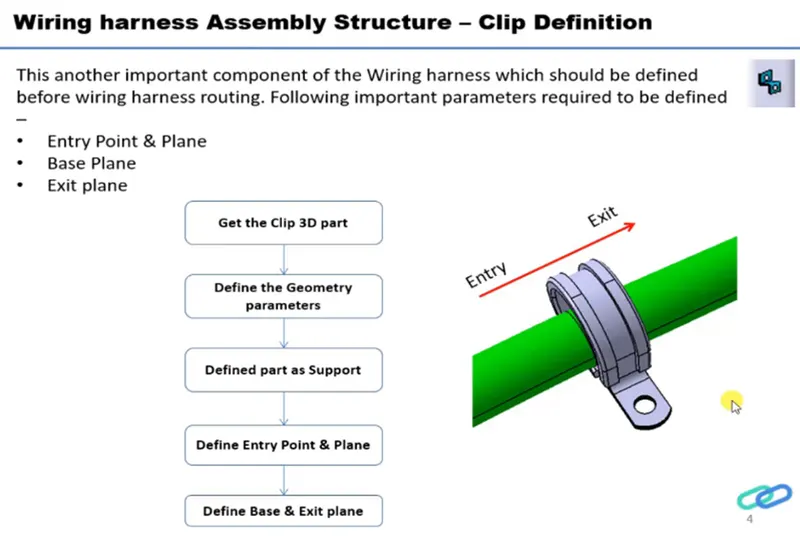
Here the given P Clamp is shown below.
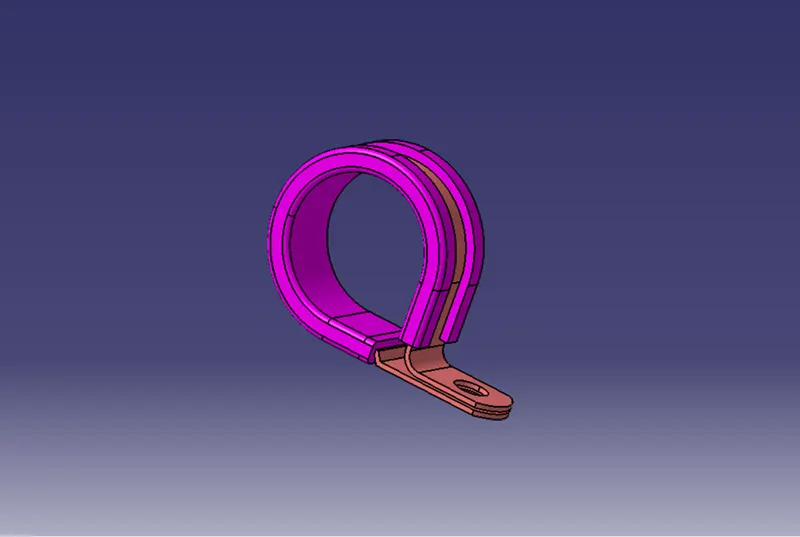
Next step is defining the Geometrical properties in the part by create Point and plane.
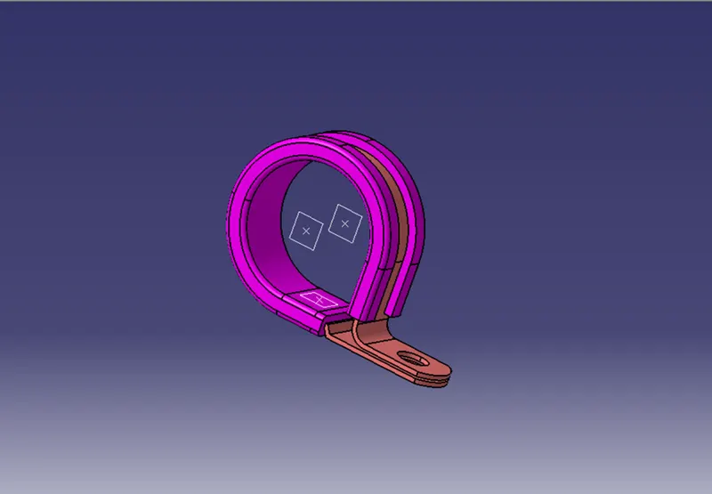
Then open the part in Electrical Part design define the part as Support by giving points (Entry, Exit and Base) and planes (Entry, Exit and Base) which is given below.
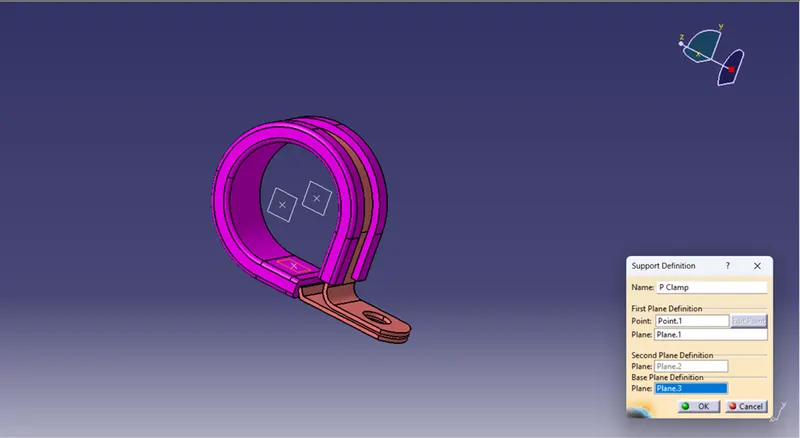
There is two entry and exit in the P clamp. So, another type is also defined which is shown below. In this type the points unable be select so the Point Tab has to be Reset by Left click in the Tab.
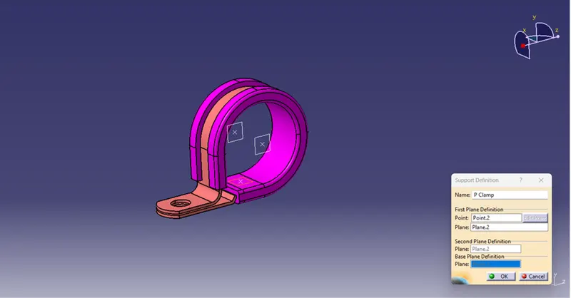
So, the final P Clamp which is defined their Electrical Properties is shown below with feature tree.
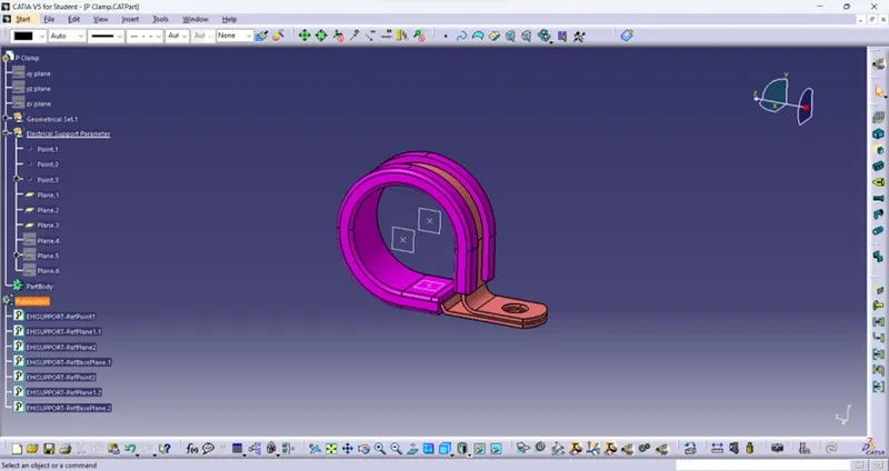
QUESTION 2:
Download following Back shell cad data & define it as Electrical back shell using Electrical Part design Workbench. Define all the necessary properties.
Tyco 1738312-1: https://www.te.com/usa-en/product-1738312-1.html
For defining the Electrical Black Shell Properties in the given part, the steps should be followed which is given below.
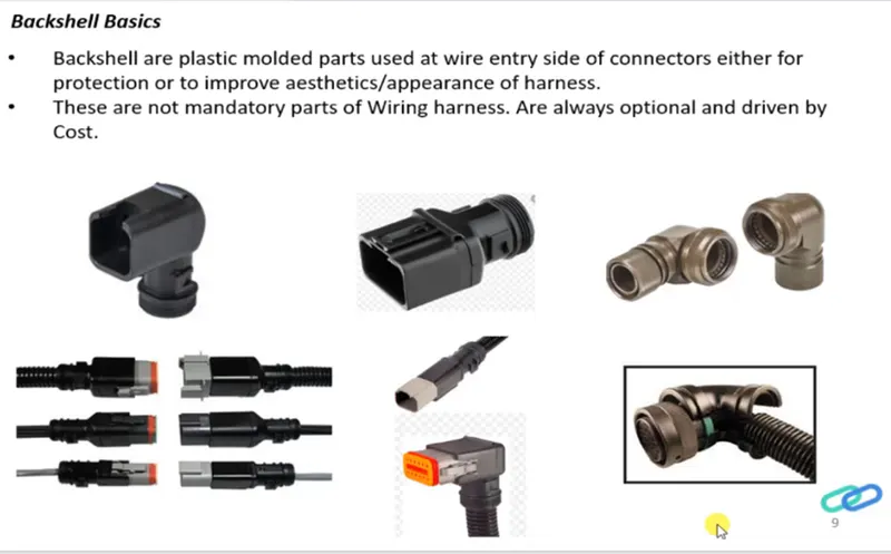
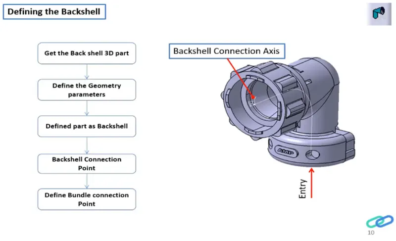
Here the given Tyco 1738312-1 part is shown below.
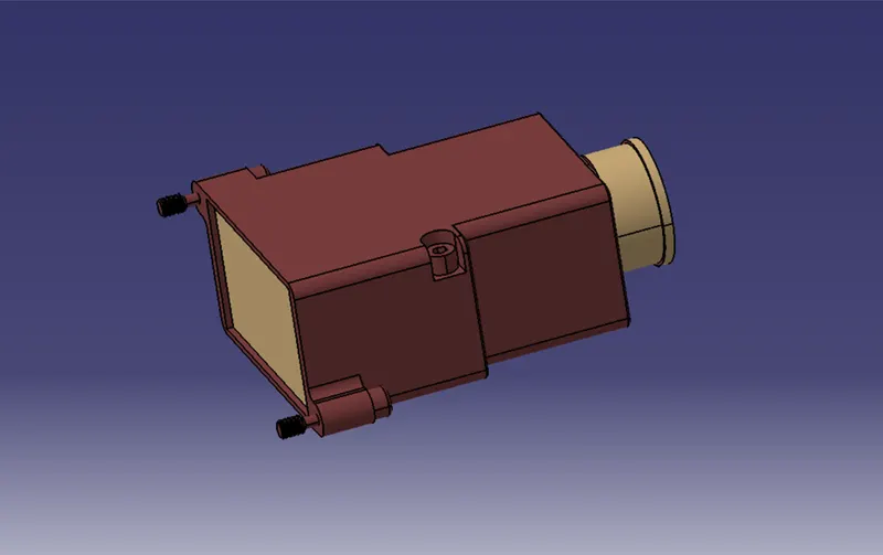
Initially the part is downloaded and open it in Part design to create Geometric Parameters such as Point and Axis for Electrical definition which is shown below.
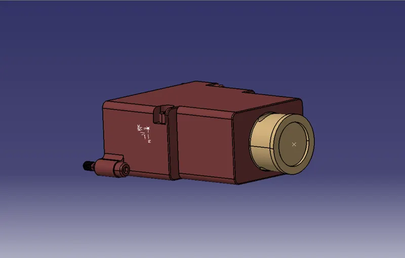
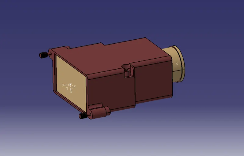
Back shell Connection:
Then the part is opened in Electrical part design and define the part as Black Shell by selecting Point, Axis and Face which is shown below.
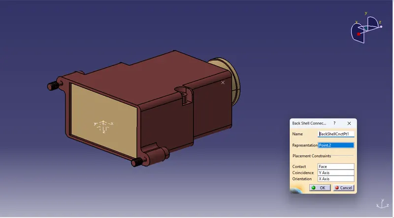
Bundle Connection Point:
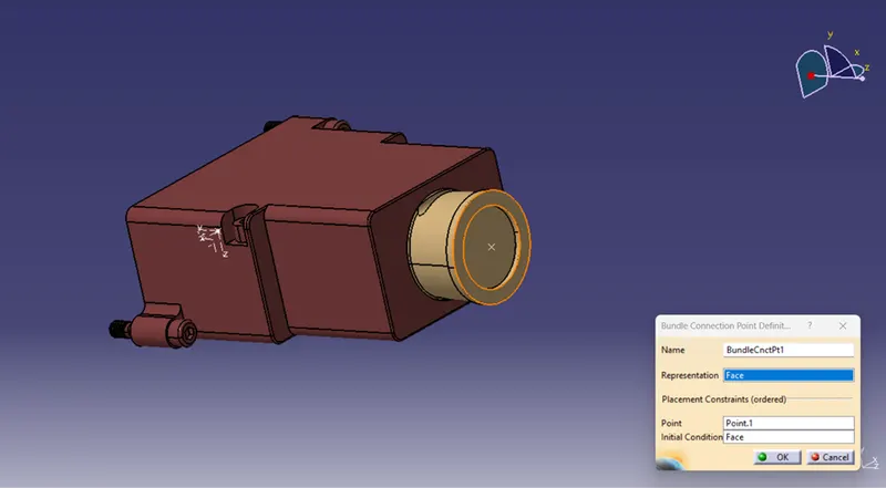
By clicking bundle Connection point definition Face and Point are select as shown below for defining the part as Bundle connection point.
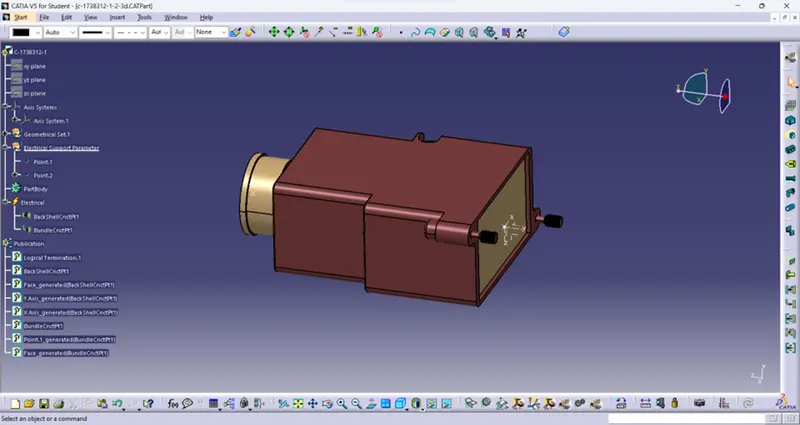
Finally, all the given electrical properties are created and defined in the given part which shown below with Feature tree.
QUESTION 3:
Create Following Corrugated tubes & add them in Catalogue under “Slit COT” family.
Given Specification:
|
Name |
ID (mm) |
OD (mm) |
Thickness (mm) |
|
15mm COT |
12 |
15 |
1.5 |
|
20mm COT |
17 |
20 |
1.5 |
|
35mm COT |
32 |
35 |
1.5 |
|
10mm COT |
7 |
10 |
1.5 |
|
5mm COT |
3 |
5 |
1 |
Catalog Creation:
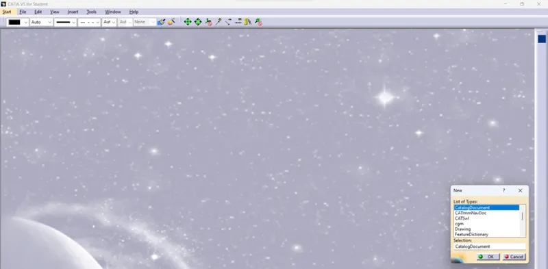
Before create the Corrugated tube there should be Catalog will create in the name of Slit COT for saving. Initially required files to be created by Option --> New --> CatalogDocuments shown in below.
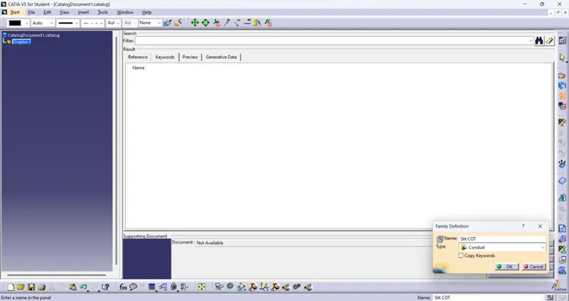
Then by clicking Add family --> Slit COT as Name and Conduit as Type and click Ok. Then it is saved in Catalogue folder as shown below.
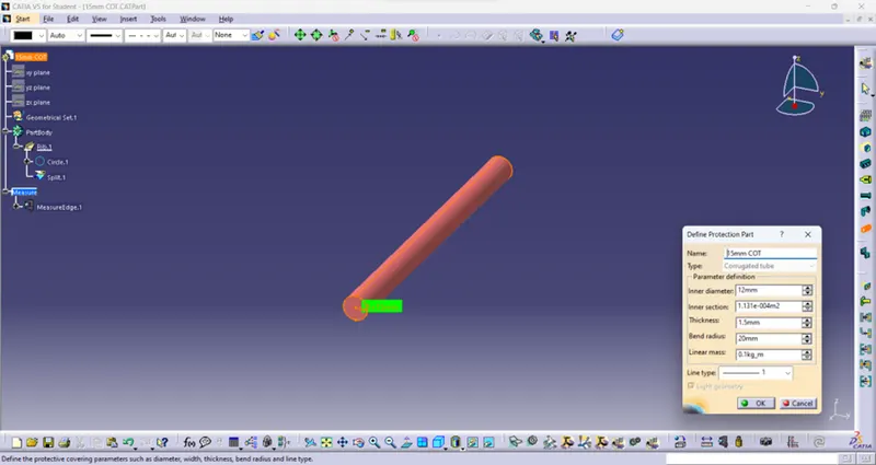
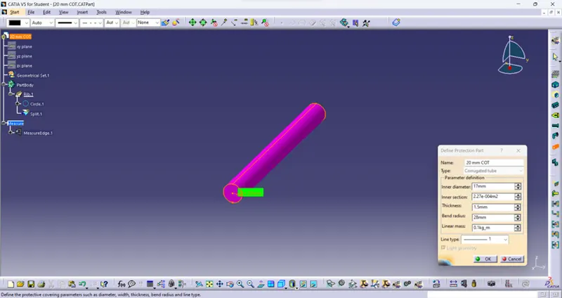
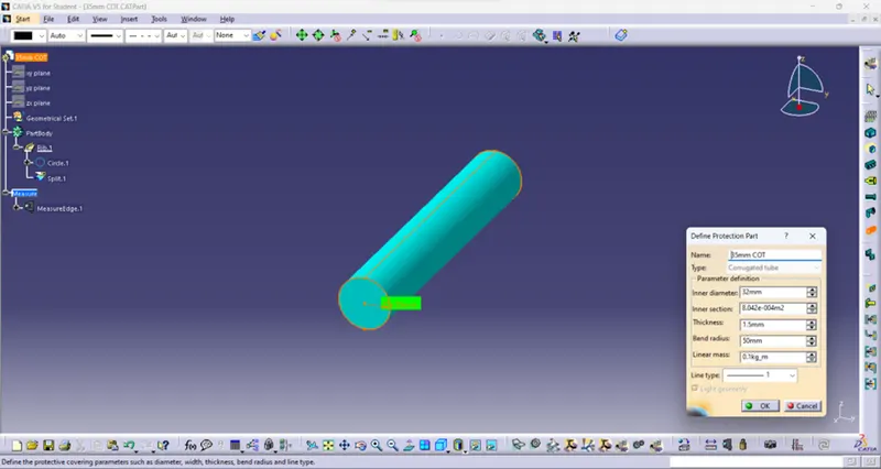
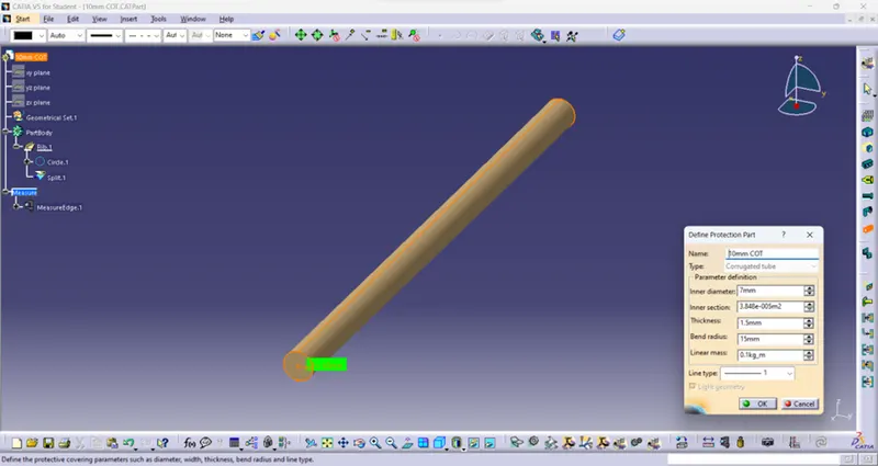
For create the tube steps are same but the specification is changed for respective tubes. First open the new part in Electrical Design Part and select Define Protection part then click Part name and TAB is open then given the values such as Inner diameter, Outer Diameter and Thickness.
Here the bend radius is given which 1.5 times greater than the inner radius. The 5 corrugated tubes are created which is shown below with feature tree.
15mm:
20mm:
35mm:
10mm:
5mm:
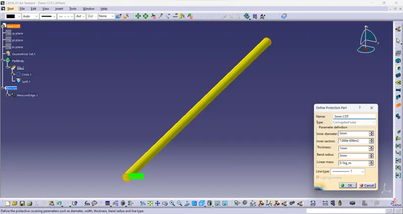
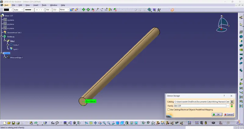
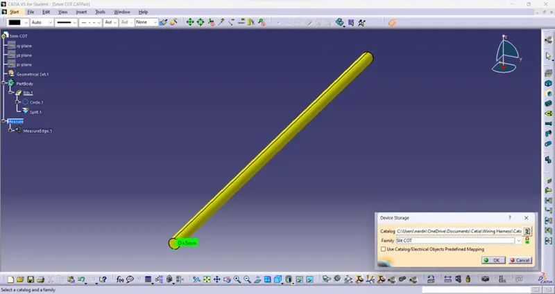
Then all the parts are stored in Slit COT Catalog by click Store device path file is catalog and Family is Slit COT.
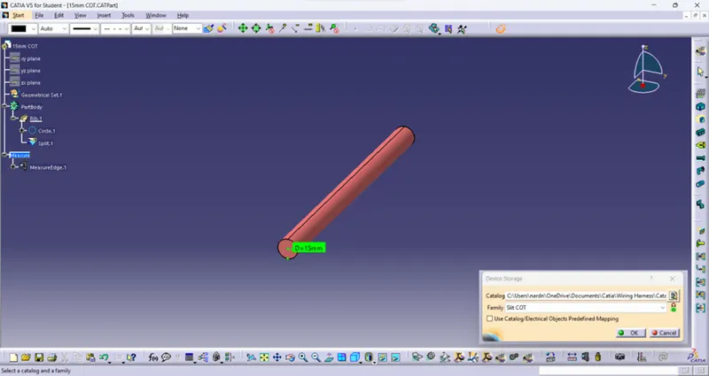
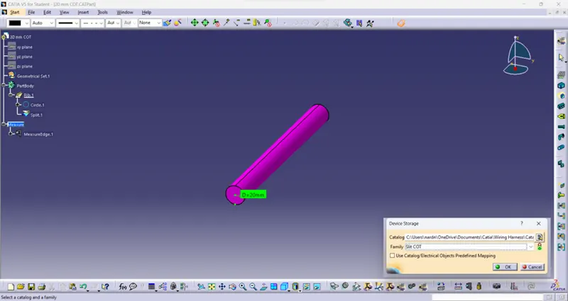
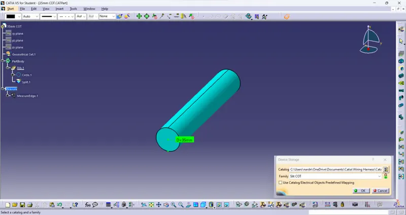
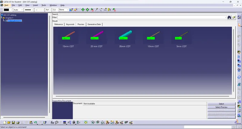
Corrugated tubes which are stored in Slit COT family catalog is shown in below by open the catalog file.
CONCLUSION:
Thus, all the given parts are defined as Electrical properties by downloading the files and also the corrugated tubes are created under Slit COT family catalog by given specification.