Modelling of 25 storey building with the specified properties using ETABS
AIM: To model a 25 storey building using ETABS with reference of IS 1893
Introduction: ETABS is an engineering software product that caters to multi-story building analysis and design. Modeling tools and templates, code-based load prescriptions, analysis methods and solution techniques, all coordinate with the grid-like geometry unique to this class of structure. Basic or advanced systems under static or dynamic conditions may be evaluated using ETABS. For a sophisticated assessment of seismic performance, modal and direct-integration time-history analyses may couple with P-Delta and Large Displacement effects. Nonlinear links and concentrated PMM or fiber hinges may capture material nonlinearity under monotonic or hysteretic behavior. Intuitive and integrated features make applications of any complexity practical to implement. Interoperability with a series of design and documentation platforms makes ETABS a coordinated and productive tool for designs which range from simple 2D frames to elaborate modern high-rises.
Procedure:
STEP 1
- Open E-Tabs ->new file
- A new tab will open
-

- Use built in settings ->change the units and codes as per indian standard->Click Ok
- A new tab will open
STEP 2
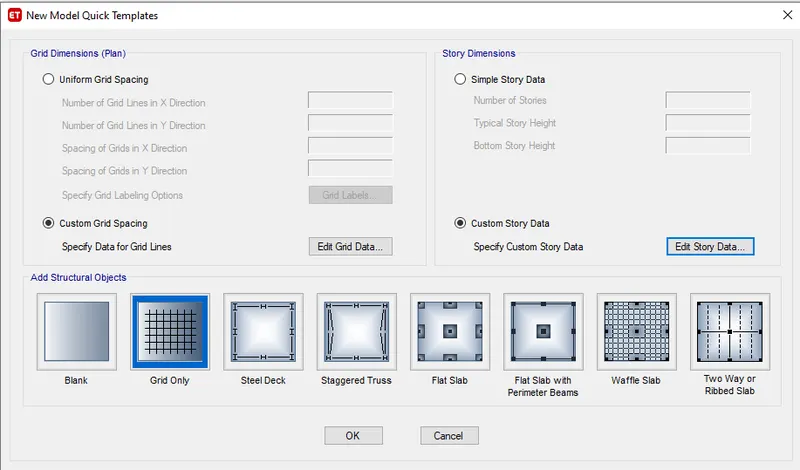
- Click on custom grid spacing->Edit grid data->A new tab will open
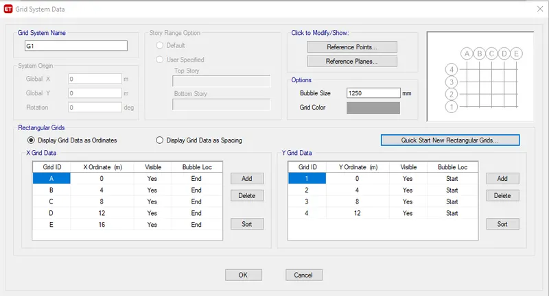
- Enter the grids ordinates in X direction And Y direction
- Click on Add to made more grids as pers requirement->Click on Ok
- You will be brought back to the previous page(Quick templates page)
- Click on custom storey data->A new tab will open
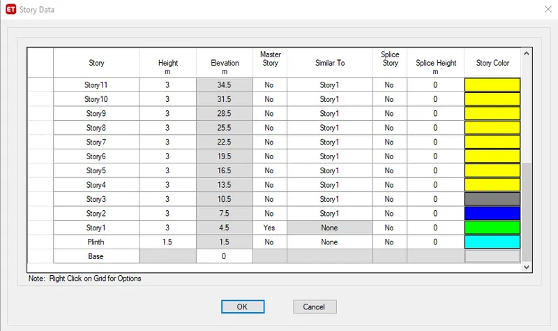
- Right click on and select "add new story"->Enter number of story you want->enter distance between them
- Select story 1 as the master story and all athers as No(as shown in the above pic)
- Select siimilar to "Story 1"->SO that all other story will be similar to story 1
- Click Ok
STEP 3
- Will be taken to template page->click Ok
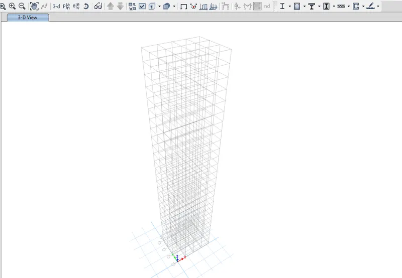
- The main page will open showing the building structure you designed(shown below)
STEP 4
- Click on Define bar->material properties->a new tab opens
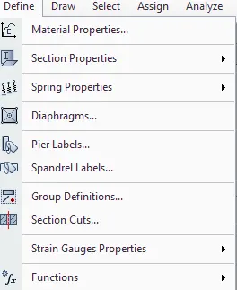
- after selecting material properties->new tab will open
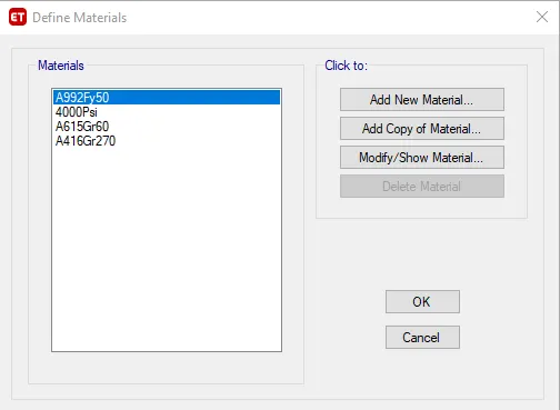
STEP 5
- Click on add new material->New tab opens-.selct as per the standard(concrete/rebar etc.)
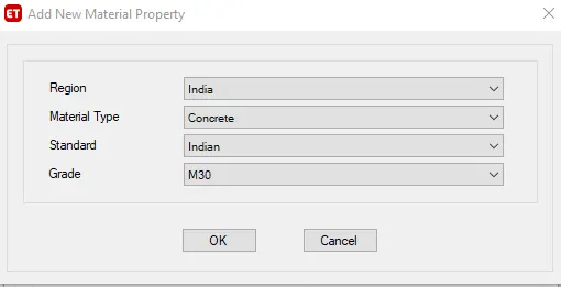
- Next we need to check material property data
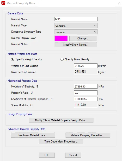
STEP 6
- Next we need to add rebar as the materail
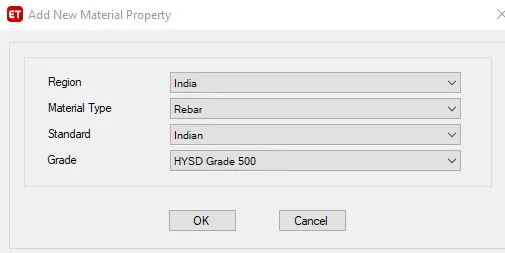
- we need to check material property data of the HYSD bar
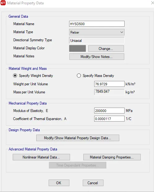
- click on OK
STEP 7
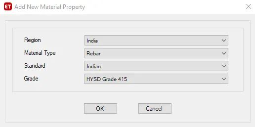
- Also do the same for 415 rebar similar ot the abive 500HYSD
STEP 8
- After adding the material properties->we have to add the column and beams sections
- Go to define->section properties->frame sections
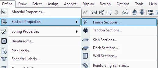
- a new tab will open->Click on Add new property
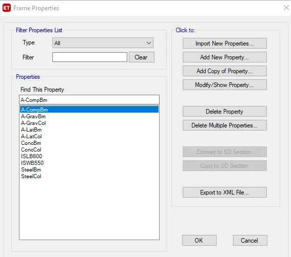
STEP 9
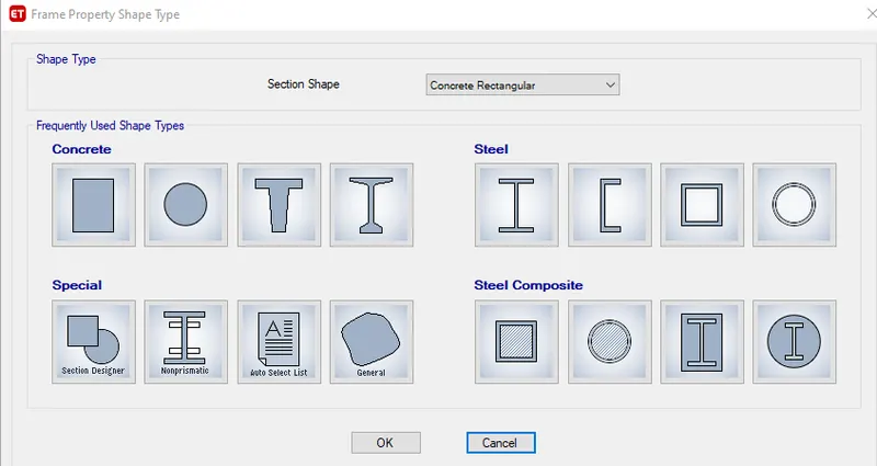
- After click add new property->A new tab open ->from here select the rectangular concrete and click ok
- To add new beam and column frames
- Next a frame section property data will open->you have to enter the data for the beam and columns
- Change the property name as pers given data B300x400->change material in to M30
- enter the depth and widht of the sections
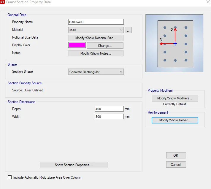
- Click on Modify/show rebar->to enter the rebars types and numbers
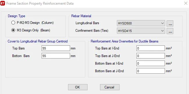
- A new tab will open->click on M3 design only
- Change longitudnal bars and Ties bar types to the one you made before
- Enter the covers distance ->click on OK
STEP 10
- Again on frame sections->Add new property
- Select the rectangular concrete section->click on OK
- A new tab open->rename the property as C800x800
- Enter the width and depth of the column
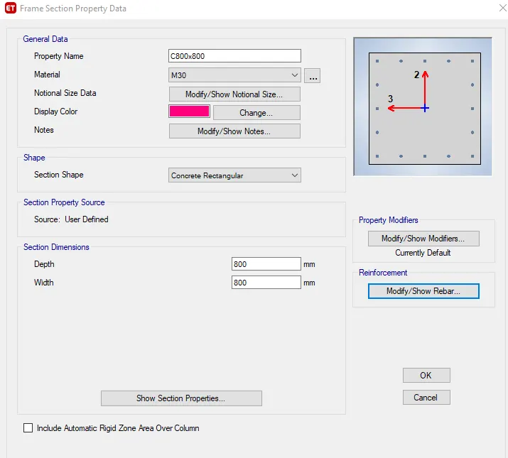
- Click on modify/show rebar->To enter the bars type of clumns
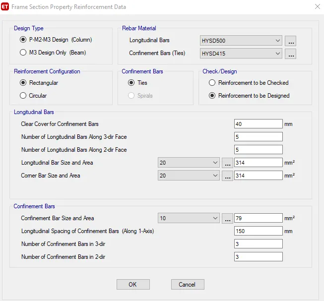
- A new tab will open->click on P-M2-M3 design->Enter longitudnal and tie bars type
- reinforcement to be designed->Enter the number of bars your want in 2&3 direction
STEP11
- Next we select the slab section for the slab of 150mm
- Go to define->section properties->slab sections
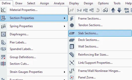
- A slab properties tab will open->Click on slab1 ->modify/Show property
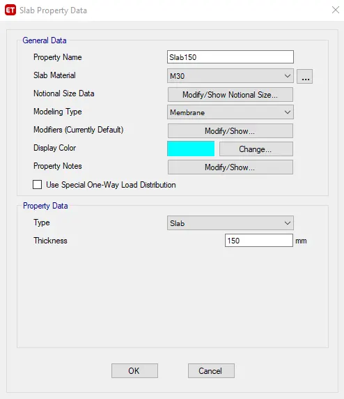
- Slab property data tab will open->rename the slab as Slab150
- select the slab material as M30->Modeling type as "membrane"
- enter the thickness of the slab->click OK
STEP 12
- Now we will add columns to the structure.
- Go to bottom right corner and select ALL STORIES
- Click on "Quick draw columns" of left side toolbars->a new tab will open
- select the C800x800 from the property
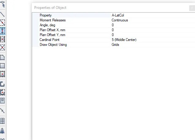
- select all the columns ->all the columns will be applied to the grids
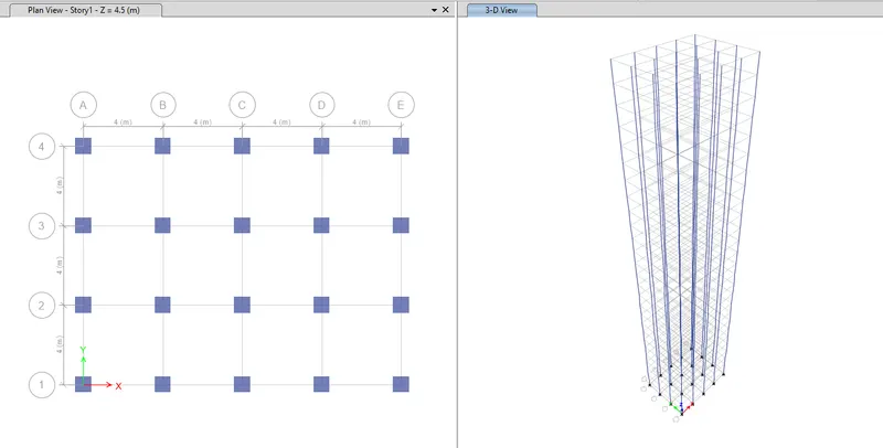
STEP 13
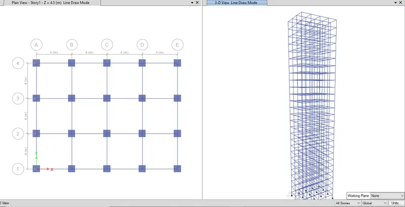
- Now beam will be added->Select quick draw beams (keep the selection to ALL stories)
- a tab will open->select the property to B300x400
- select all the beams section->the beams will be applied
STEP 14
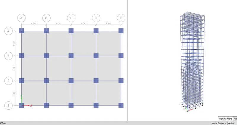
- Now add slabs to the section-Select quick draw floors/Slabs
- a tab will open->change the property to slab 150
- Change the selection To similar stories
- select all the slabs of any one floor ->the floors will be applied
STEP 15
- Now joints will be added to the base
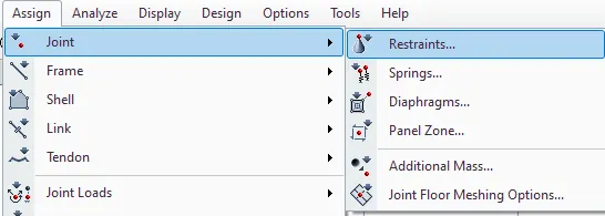
- Goto Assign bar->Joints->Restraints
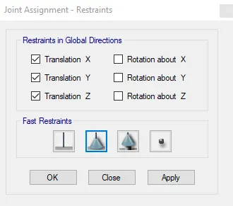
- A new Joint assignment tab will open->select the pin joint
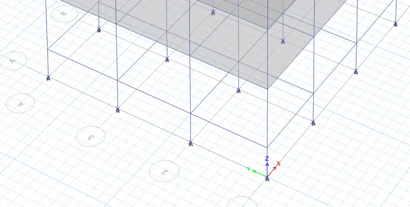
- Now the pin joint is assigned to the base of the columns
STEP 16
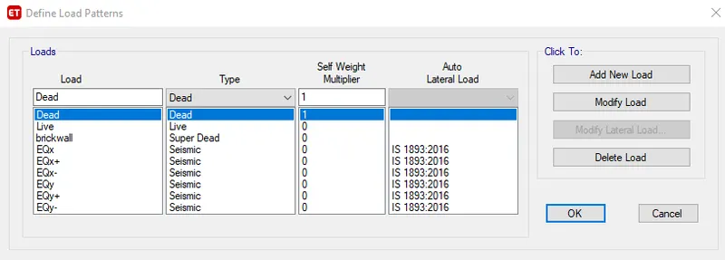
- Now we need to define load patterns->Go to Define Bar "Load patterns"
- Add dead load ,live load,brickwall load and earthquake load as shown below
- Now we have to modify the earthquake load as per the direction of applications
- To modify ,click on earthquake loads "EQx-" ->CLick on Modify lateral load
- A new tab will open-> select only the Load direction you want(X dir-eccentricity in this case)
- Select Site III as suggested in the question & time period user defined 0.5 sec
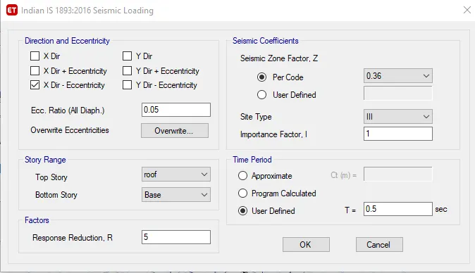
Do this for all the earthquake directions,just change the eccentricity and direction in the above
STEP 17
- Now we have to assign the live load to the slabs and brick wall loads
- Select all the slabs of any floor
- Go to Assign->Shell loads->Uniform
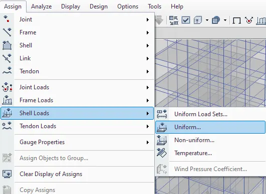
- A Shell load assignment will open->Input a live load of 3 KN/m^2 as per the question
- Make sure the similar stories are selected
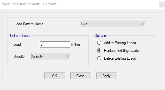
- Now the live load is applied to all the floors
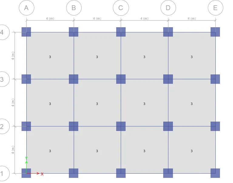
STEP 18
- Now the live load will be applied on the roof
- Go to the roof plan->Change the selection into One story
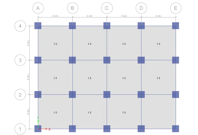
- select all the slabs of the roof
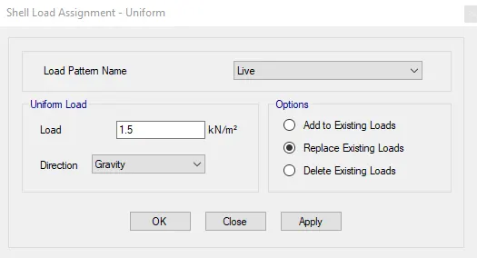
- Go to assign->shell loads->Uniform
- Put live load of 1.5KN/m^2 (the roof has live load of 50% of the floor)
STEP 19
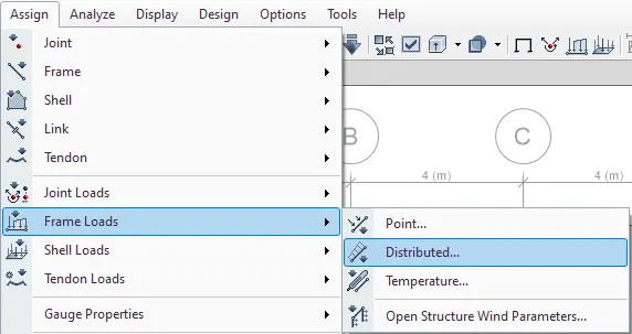
- Now assigning the brickwall load to the beams //Make sure u change the selection to all stories
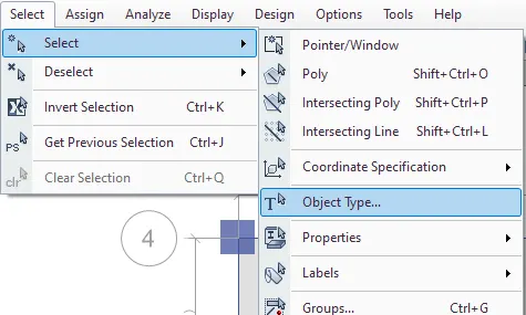
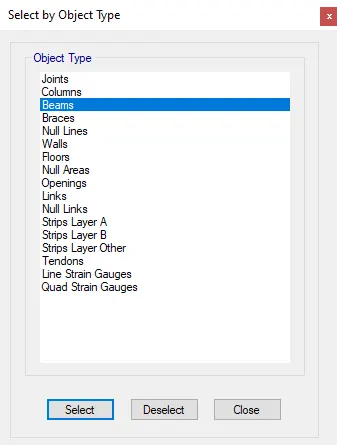
- GO to select menu->object types->select beams(all beams will be selected)
- Now go to Assign menu->Frame load->distributed
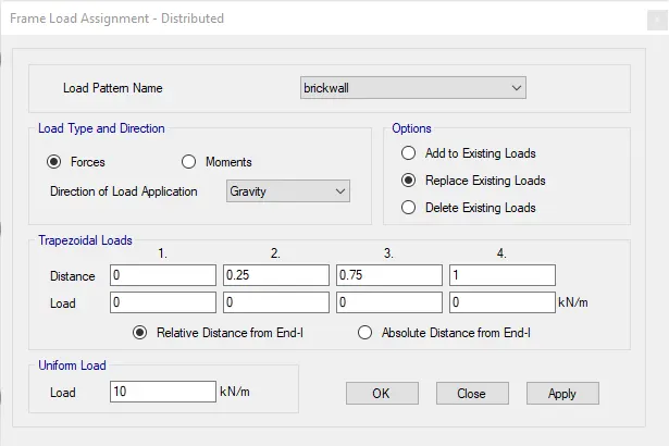
- load assessment tab will open->select the brickwall from the selection
- enter the value of 10KN/m
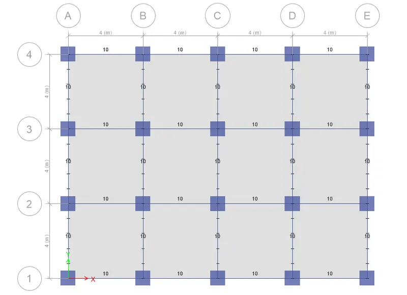
- brickwall is distributed all over beams
STEP 20
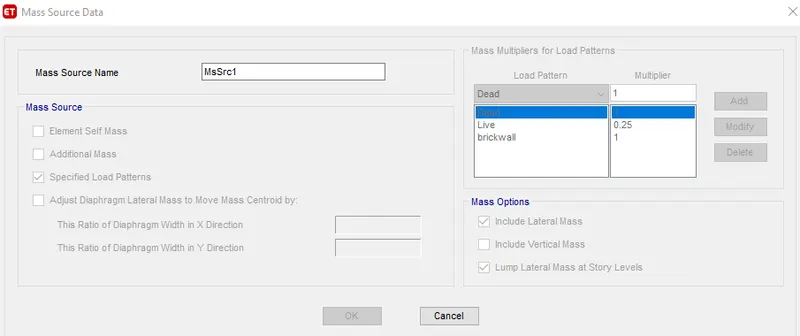
- Now we define mass source
- Go to Assign Menu->MAss source
- A new tab will open->Click on Modify/show mass source
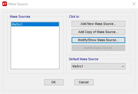
- modify tab will open->select specified load patterns
- Input dead=1,brickwall-1,live=0.25
STEP 21
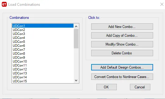
- Now load combination will be defined
- From the define menu->go to load combination
- a new tab will open->click on Add default design combos
- Select concrete frame design
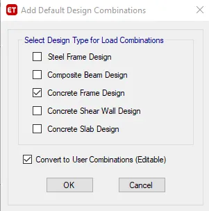
- Click oK
STEP 22
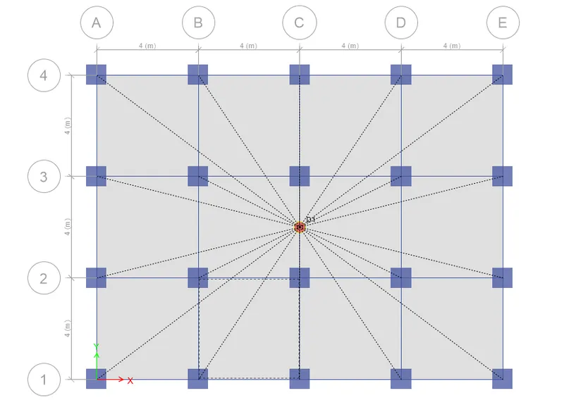
- MAking the diaphragm of the structure
- Go to select menu->object types->seelct the floors
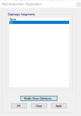
- Assign->Shell->Diaphragm
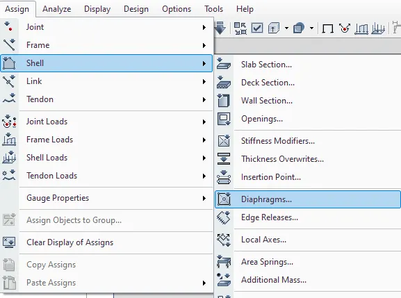
- A new tab will open->in that select D1 and apply
STEP 23
- Now we check the model for errors
- Go to analyze menu->check model
- A new tab opens->tick all the checks
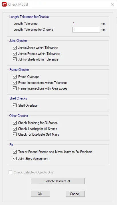
- A no error mesage will be shown if there are no errors in the structure
STEP 24
- Now Go to analyze menu->run analysis->analysis will take some minutes
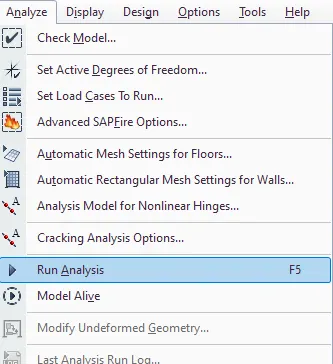
- Go to "Show deformed shape or F6"->Tab will open and select any case(live/dead,earthquake) you want view the deformed shape
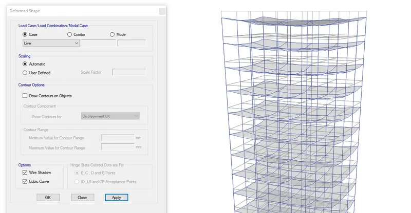
Check on all other cases and see the deformed shapes
STEP 25
- click on Display menu->Show tables->TAbles display will open
- select anaylysis results->structure output->modal information->Modal participation mass ratios
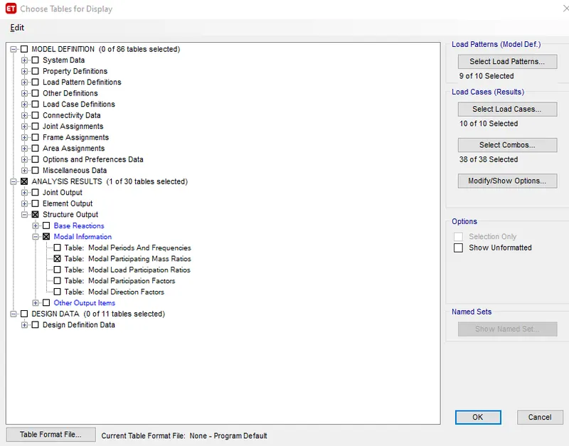
- A Modal participation mass ratios table will appear with all the mass ratios action on the builidng
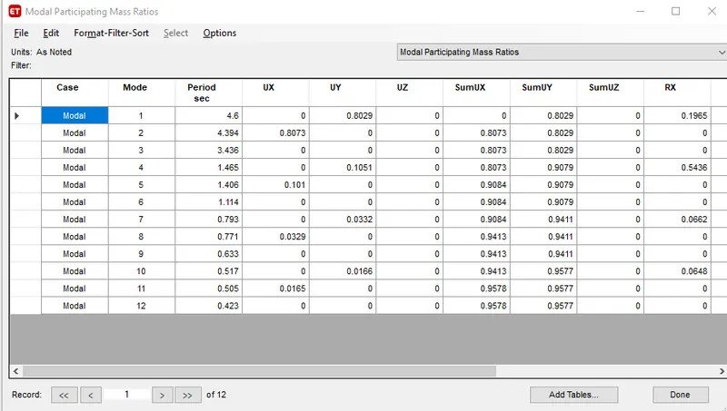
- From table Natural time period of mode1 is noted and torsional DOF is noted
- Tx1=4.6sec,Ty1=4.394sec and Txy=3.436sec
- so it is clear from the table that the torsional time periiod is less than the two translational time period as required by IS 1893 provision table 5
CONCLUSION: The analysis is done and the result is within the range.