Analysis & Design of RCC shear walls in the model using ETABS
Aim: To analyse and design RCC shear wall using ETABS
Introduction:
One of the useful tools in ETABS program is the Shear Wall Design capability. It is not only limited in the analysis of walls but it can also perform the design and check. The designer can be opted to either use the Reinforcement to Designed or Reinforcement to be checked option. When you require the program to do the design, choose the Designed option and Checked when you let yourself assigned the wall reinforcement to be verified by the program.
In an ETABS analyzed model, the program can perform the following design/check, the procedure in accordance with the specified code requirement:
- Design and Check of concrete wall piers for flexure
- Design of concrete wall pier for shear
- Design of concrete shear wall spandrels for flexure
- Design of concrete shear walls for shear.
When the pier section is specified to check for the rebar details specified by the designer, the program creates an analysis to determine the flexural demand/capacity ratio, the required area for shear rebar for the selected pier and other output results to determine whether the section is passed or failed.
Procedure:
1. Download the given 6 storey building
2. Change the plan view from mumty to terrace such that we can see proper shear walls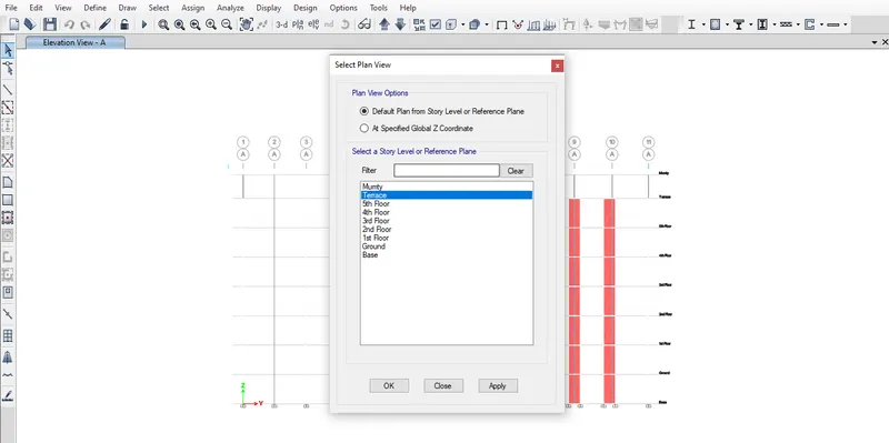
3. Then select the All Stories option
4. Select the grid 11 and view its elevation along it.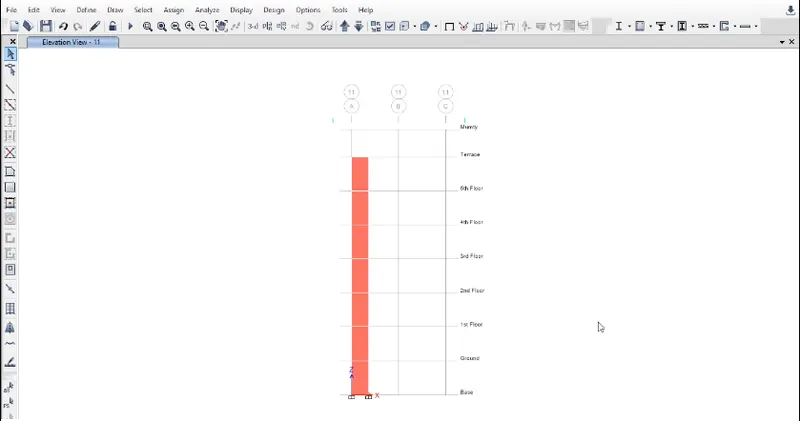
5. Also ensure that pier assignment is done by clicking on labels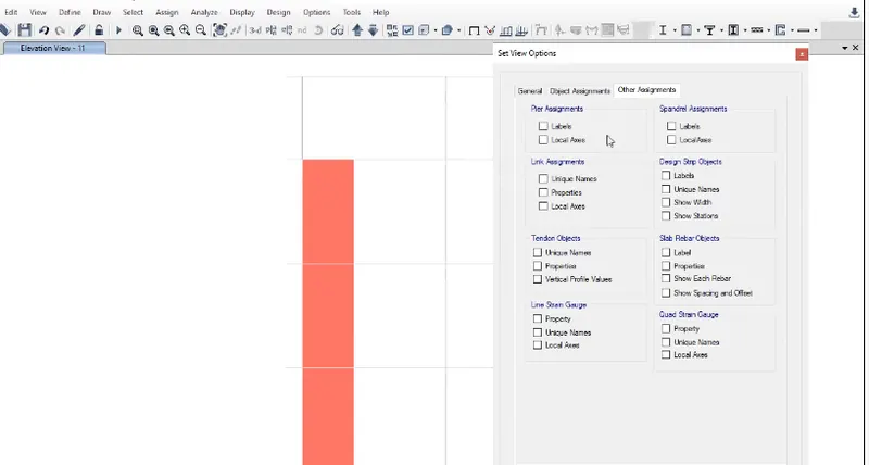
6. Run the analysis
7.Clicking the concrete frame design tool
8.Choosing to display the longitudinal reinforcement
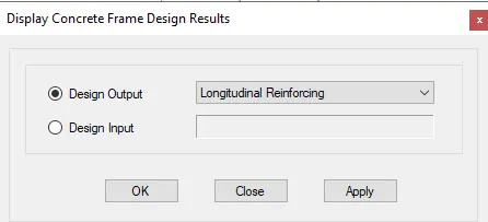
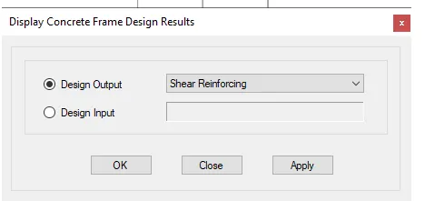
9. Choosing to display the Shear reinforcement
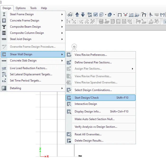
10. selecting display info of shear wall
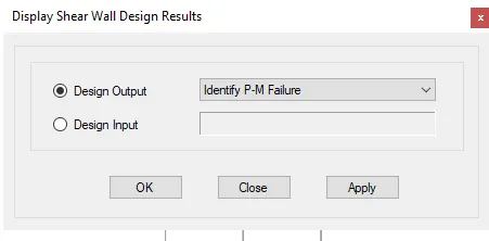
11.Selecting the P-M failure design output.
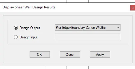
12.Selecting the Pier edge/ boundary zones widths design output.
Step-13:
Reviewing the design output of ETABS, the boundary element widths are fixed with two values respectively 450mm (from base to 1st floor) and 300mm (1st floor to terrace). The longitudinal rebar and shear rebar also categorised in same respect and detailed using AutoCAD software.
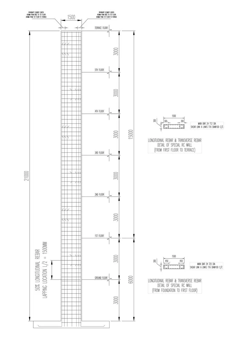
Verification with IS13920-2016:
a) Overall height of wall h = 21000mm, Length of wall L = 1500mm
Ratio (h/L) = 21000/1500 = 14 > 2
The given RC wall is slender.
b) The largest diameter than can be used in RC wall should not exceed 1/10th of thickness of wall. So 300/10 = 30mm
We used 25mm dia rebar in the detailing. Hence OK.
c) The maximum spacing of longitudinal / transverse rebar should not exceed (i) 1/5th of horizontal length(L)=1500/5 =300mm
(ii) 3 times of thickness (t) = 3 x 300 = 900mm
(iii) 450mm
So we have to adopt maximum 300mm spacing both for vertical and horzontal rebar inside RC wall.
d) Minimum horizontal reinforcement calculation as per Table-1 of IS13920-2016
(ρh)min">(ρh)min(ρh)min= 0.0025 + 0.5(hwLw-2)(ρh-0.0025)">(hwLw−2)(ρh−0.0025)(hwLw-2)(ρh-0.0025)
= 0.01672 of cross section of RC wall
= 1500 x 300 x 0.01672 = 7524 sq.mm for entire RC wall height.
= 7524 / 21 = 358 sq.mm /meter height of RC wall
We already provided 16mm dia at 100 mm c/c spacing which will give = 1000/100 x 2 x 201 = 4020 sq.mm
Hence OK.
e) Minimum boundary reinforcement calculation as per Table-1 of IS13920-2016
(ρv,be)min">(ρv,be)min(ρv,be)min= 0.008
= 0.008 x 300 x 300 = 720 sq.mm
We already provided minimum 8 numbers 12mm dia rebar = 8 x 113 = 904 sq.mm
Hence OK.
f) Minimum web reinforcement calculation as per Table-1 of IS13920-2016
(ρv,web)min">(ρv,web)min(ρv,web)min= 0.0025
= 0.0025 x 900 x 300 = 675 sq.mm
We already provided minimum 8 numbers 12mm dia rebar = 8 x 113 = 904 sq.mm
Hence OK.
g) Minimum overall RC wall vertical reinforcement calculation as per Table-1 of IS13920-2016
(ρv,≠t)min">(ρv,≠t)min(ρv,≠t)min= 0.0025 + 0.01375 (twLw)">(twLw)(twLw)
= 0.00525 times of wall cross section
= 0.00525 x 1500 x 300 = 2363 sq.mm
We already provided minimum 24 numbers 12mm dia rebar = 24 x 113 = 2712 sq.mm
Hence OK.
h) Boundary element special confining reinforcement as per Clause 10.4.4 of IS13920-2016:
Ash=0.05Svh(Fckfy)">Ash=0.05Svh(Fckfy)Ash=0.05Svh(Fckfy)
Maximum spacing of confinement is 100mm as per drawing
h = minimum clear distance between longitudinal rebar = 150mm say
Ash=">Ash=Ash=45 sq.mm
We already provided two closed links of 16mm dia = 2 x 201 = 402 sq.mm
Hence OK.
Conclusion:
Thus we have designed the specified RC wall and detailed using AutioCAD software. Also the clauses from ductility code Indian standard IS13920-2016 are verified for the RC wall detailing.