Creation of Multiple viewports, Scaling the drawing and setting in Template in AutoCad
AIM:
To create Multiple viewports, Scaling the drawing and setting in Template in AutoCad.
INTRODUCTION:
The main objective of this project is to understand about the viewports in Auto CAD.
There are two types of viewports in AutoCAD. Model space viewports and layout space viewports.
Viewports are areas that display different views of our drawing and/or model. Layout viewports are objects that you can scale to display the view of your drawing on a layout tab for publishing and production. In model space, you can split the drawing area into one or more rectangular areas called model space viewports. Viewports are areas that display different views of your model. In large or complex drawings, displaying different views reduces the time needed to zoom or pan in a single view. We can configure these viewports from the View tab on the Ribbon.
various features of viewports is as given below
- Commands that control the view, such as panning and zooming, apply only to the current viewport.
- Commands that create or modify an object are started in the current viewport, but the results apply to the model and can be visible in other viewports.
- You can start a command in one viewport and finish it in a different viewport.
- You can make any viewport the current one by clicking in it.
You can modify the size, shape, and number of model space viewports in a viewport configuration:
- Choose from several viewport configurations by clicking the [+] or [-] control in the top-left corner of a viewport.
- Drag the boundaries of viewports to adjust their size.
- Press CTRL while dragging viewport boundaries to display the green splitter bar and create new viewports. Alternatively, you can drag the outermost splitter controls.
- Drag a viewport boundary onto another boundary to remove a viewport.
TASK 1:
To create a layout of the Plan and Section A of the project in Challenges 7, using the template Tutorial-mArch.dwt in a scale. Use the MV command to create the viewport . Also, use ATTEDIT command to edit the information in the title block. Use A1 size for the layout. Take a plot.
| As the entire plan was drawn before on project 7, Here only the required drawings like plan and section are shown to understand about view ports. | 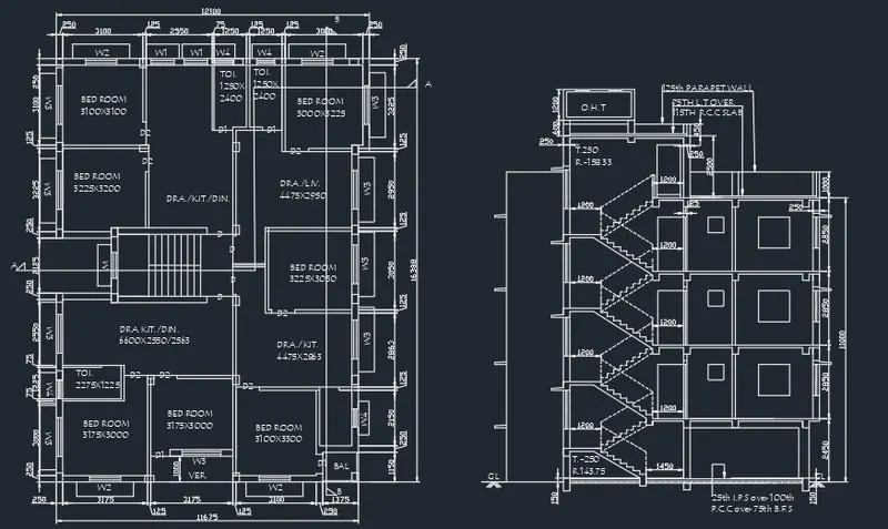 |
|
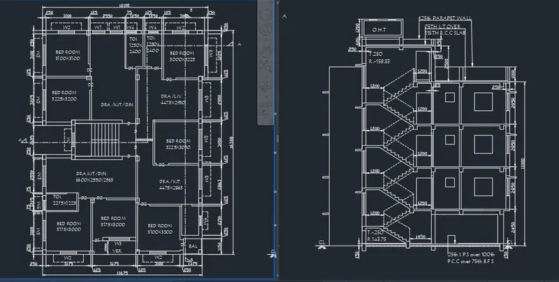
In VIEW tab,the new view option was selected to create a new view called V1 using the window option and selecting the plan from the drawing. In the similar manner V2 view of section was also created. It can be seen by selecting TWO:VEERTICAL from the VIEWPOINT CONFIGURATION window as shown. |
 |
|
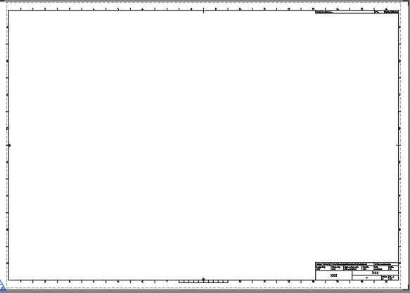
A new layout is now created using the command LAYOUT and select template and as required mArch.dwt template was selected and delete the exisiting viewport. |
 |
|
 |
|
Now using the rec command 2 rectangles of equal sizes was drawn so that it will fit in the paper. Now click MV and select object as these rectangles and in this way two model spaces was created |
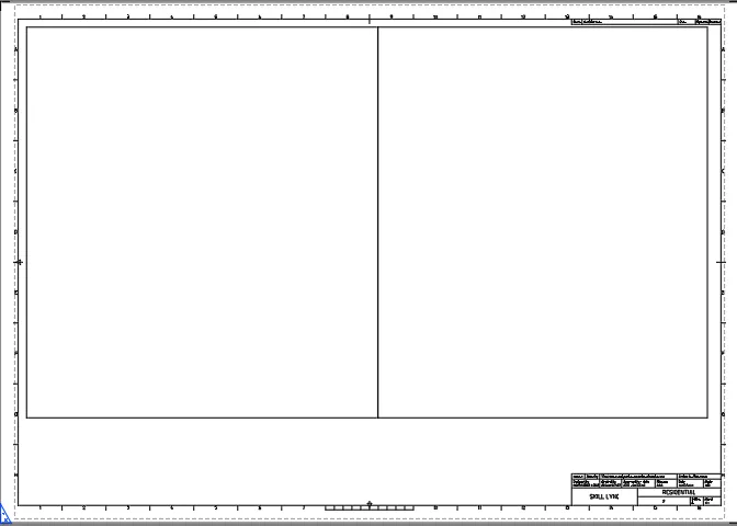 |
|
Select the required models V1 and V2 and apply it in both the rectangles. |
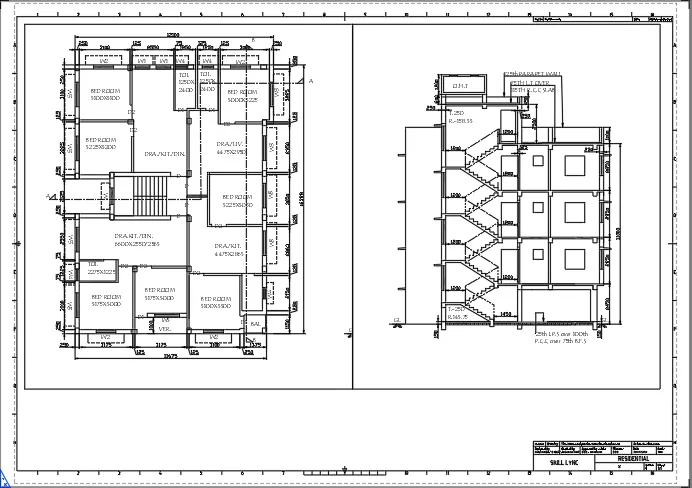 |
| Type ATTEDIT to open the edit attributes dialogue box and apply the required comments and click ok. | 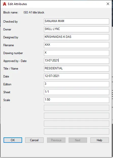 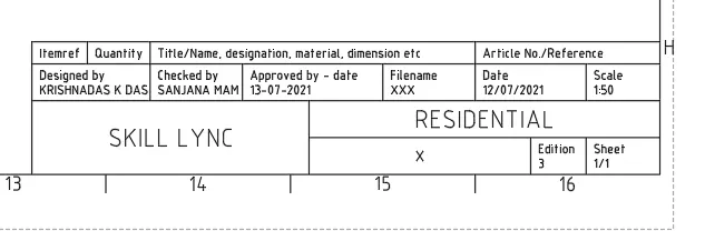 |
| Now in the paper space by selecting a suitable text and dimension style, the following dimensions was done. | 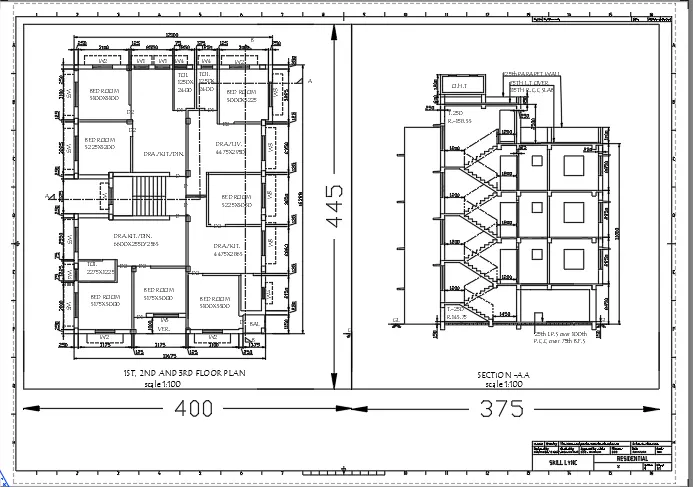 |
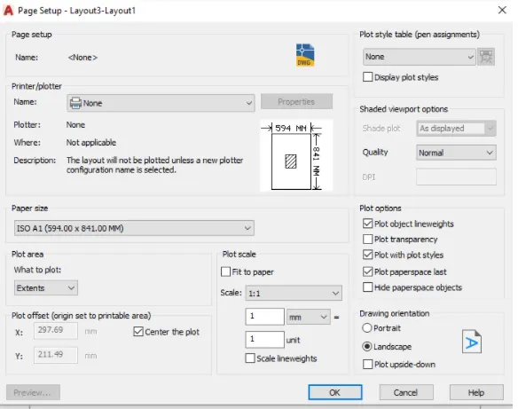
| Type PLOT to open the page setup manager the following settings was applied and click the preview option at botton. | 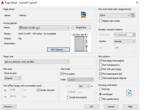 |
| The preview of the whole drawing is as shown | 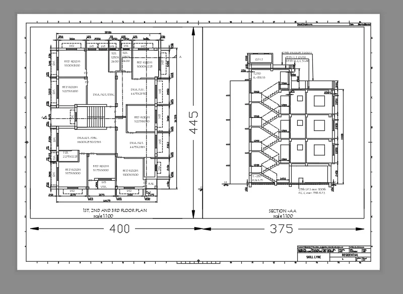 |
|
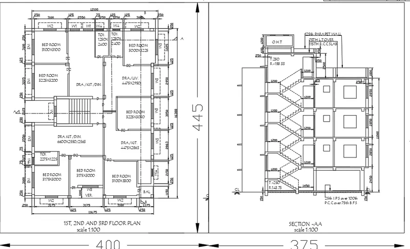
RESULTS: Layout was created using the template Tutorial-mArch.dwt in a scale. The MV commands was used to create the viewport . ATTEDIT commandwas used to edit the information in the title block. Plot was taken with the A1 page settings. ZOOMED IN VIEW IS SHOWN TO VIEW THE DRAWING DETAILS AND MEASUREMENTS
|
|
TASK 2:
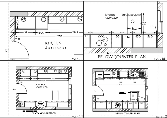
To create a layout of the Kitchen drawn in Challenge 9 as shown in Figure. Use the scale as shown in the Figure. Use A4 Size page for the layout. Take a plot.
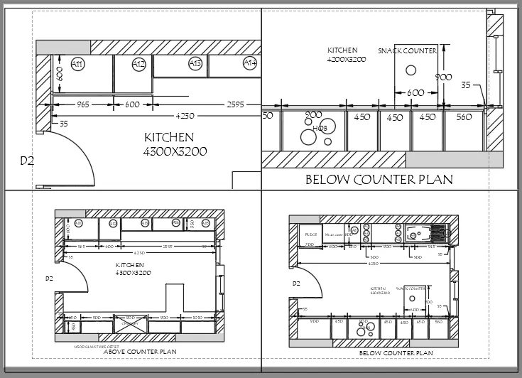
| As the entire plan was drawn before on project 9, Here only the required drawings like above and below kitchen counter parts are shown to understand about view ports. | 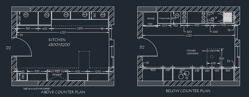 |
|
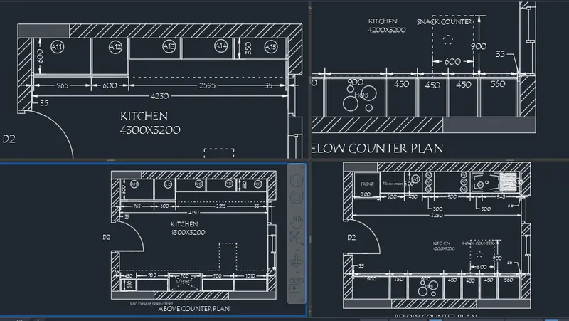
In VIEW tab,the new view option was selected to create a new view called V1 using the window option and selecting the required view from the drawing. In the similar manner V2,V3 and V4 view was also created. It can be seen by selecting FOUR:EQUAL from the VIEWPOINT CONFIGURATION window as shown. |
 |
| A new layout is now created using the command LAYOUT and delete the exisiting viewport. |  |
|
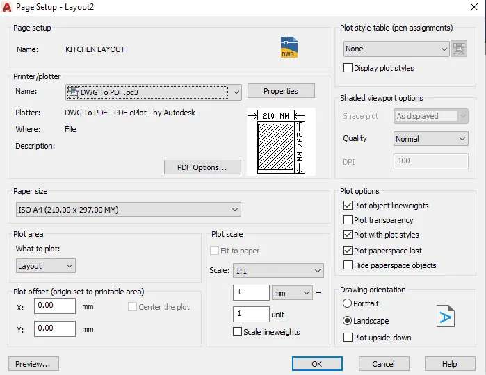
Right click on the layout and select page setup manager and modify the settings as required. We will be plotting this drawing in A4 paper |
 |
|
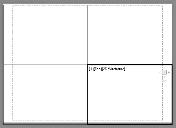
Now using the rec command 4 rectangles of equal sizes was drawn so that it will fit in the paper. Now click MV and select object as these rectangles and in this way four model spaces was created |
 |
|
Type v in command bar to open the view manager. Select the required models V1, V2, V3 and V4 and apply it in the respective rectangles. |
 |
| Now in the paper space by selecting a suitable text style, scale information was written | 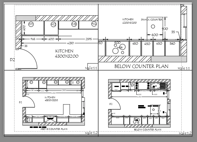 |
| Type PLOT to open the page setup manager the following settings was applied and click the preview option at botton | 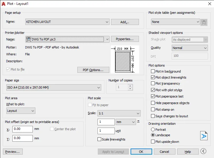 |
| The preview of the whole drawing is as shown | |
|
RESULTS: The MV commands was used to create the viewport in the scale required . Plot was taken with the A4 page settings.
|
|
TASK 3:
To create a layout of the section created in Challenges 9.
Use scale as mentioned in the Figure. Use MV command create multiple viewports. Take a plot.
| As the entire plan was drawn before on project 9, Here only the section of the industrial building are shown to understand about view ports. | 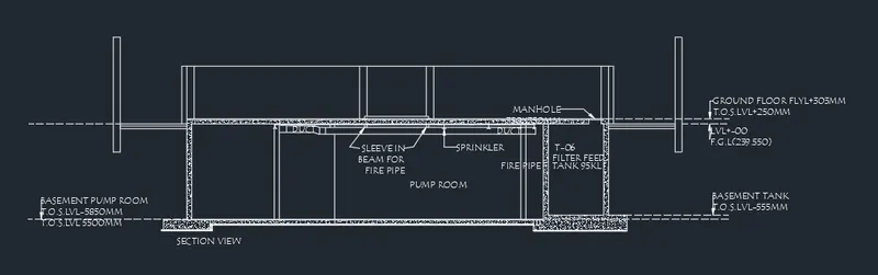 |
|
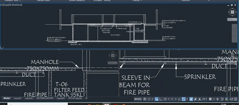
In VIEW tab,the new view option was selected to create a new view called V1 using the window option and selecting the required view from the drawing. In the similar manner V2 and V3 view was also created. It can be seen by selecting THREE:ABOVE from the VIEWPOINT CONFIGURATION window as shown |
 |
| A new layout is now created using the command LAYOUT and delete the exisiting viewport. | |
|
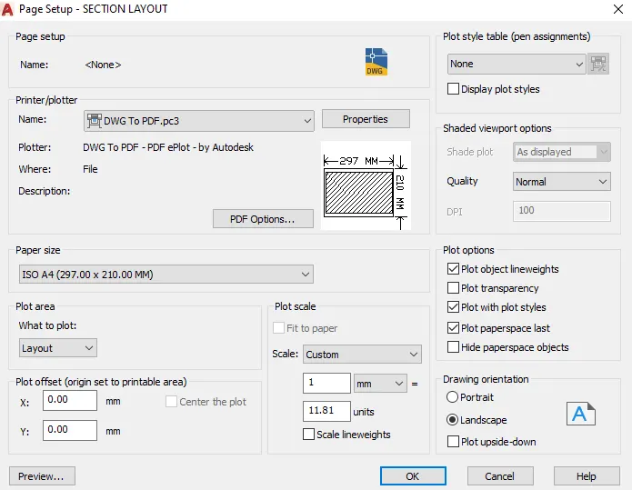
Right click on the layout and select page setup manager and modify the settings as required. We will be plotting this drawing in A4 paper |
 |
|
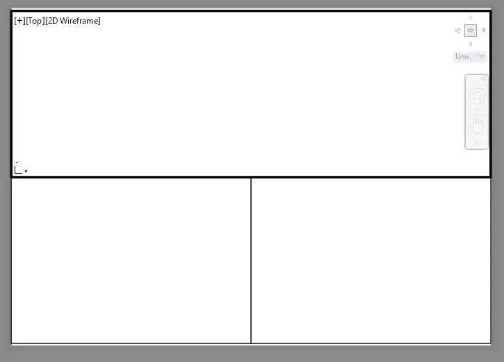
Now using the rec command 3 rectangles of equal sizes was drawn so that it will fit in the paper. Now click MV and select object as these rectangles and in this way four model spaces was created |
 |
|
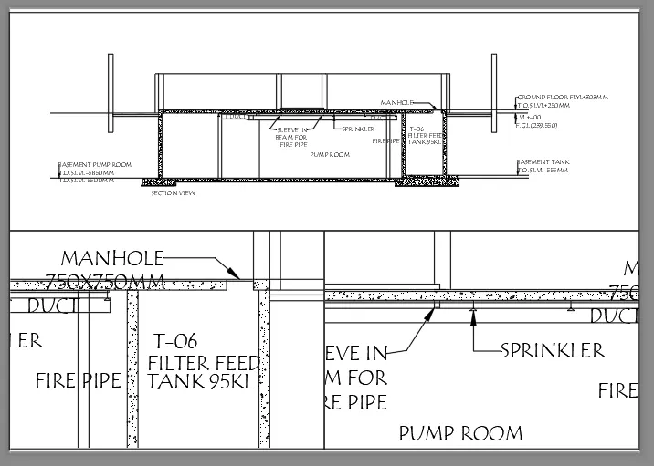
Type v in command bar to open the view manager. Select the required models V1, V2 and V3 and apply it in the respective rectangles. |
 |
| Now in the paper space by selecting a suitable text style, scale information was written | 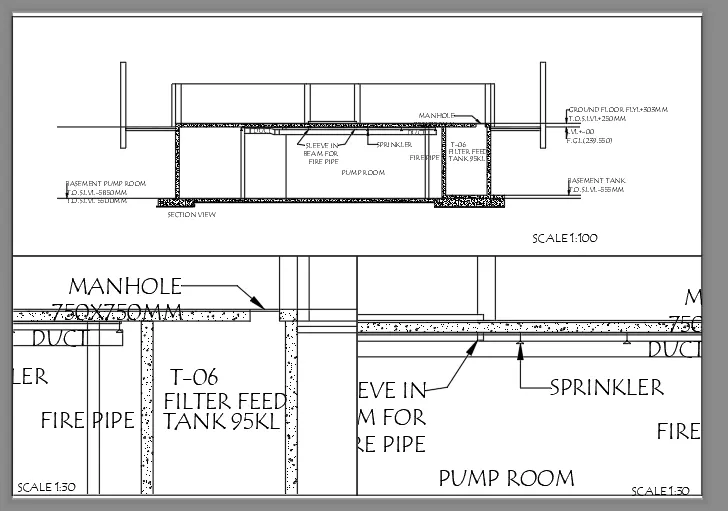 |
| Type PLOT to open the page setup manager the following settings was applied and click the preview option at botton | |
| The preview of the whole drawing is as shown | 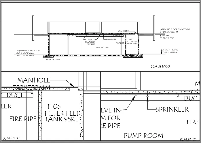 |
|
RESULTS: The MV commands was used to create the viewport in the scale required. Plot was taken with the A4 page settings.
|
|
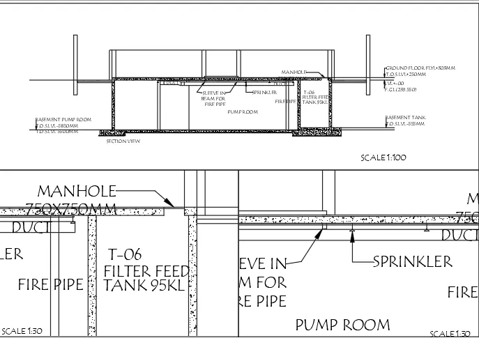
RESULTS:
TASK 1:
Layout was created using the template Tutorial-mArch.dwt in a scale.
The MV commands was used to create the viewport .
ATTEDIT commandwas used to edit the information in the title block.
Plot was taken with the A1 page settings.
ZOOMED IN VIEW IS SHOWN TO VIEW THE DRAWING DETAILS AND MEASUREMENTS
TASK 2:
The MV commands was used to create the viewport in the scale required .
Plot was taken with the A4 page settings.
TASK 3:
The MV commands was used to create the viewport in the scale required.
Plot was taken with the A4 page settings.