Project 1_Analyze and design a steel building to 10T CRANE as per IS standard code using TEKLA STRUCTURAL DESIGNER.
AIM: To analyze and design a steel building to 10T CRANE as per IS standard code using TEKLA STRUCTURAL DESIGNER.
INTRODUCTION:
Tekla Structural Designer is an integrated model-based 3D tool for analysis and design (of both concrete and steel members) in multi-material structures. Features include interactive modeling, automated structural analysis and design, drawing, and report creation.
PROCEDURE:
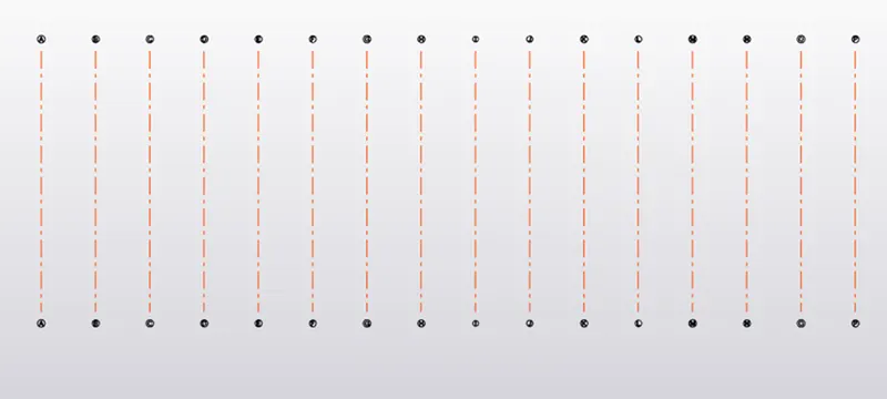
- Initially open the Tekla Structural Designer software.Now click on New option to create a new model workspace.Using the Model Ribbon using the grid line and Quick parallel grid line option the vertical grids was drawn.
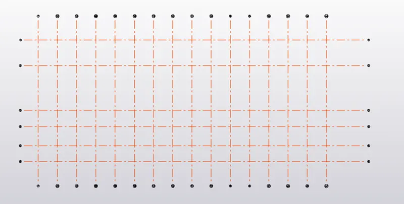
- In the same way as above vertical grid lines was drawn.
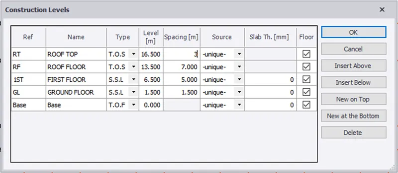
- In the Model toolbar select Construction levels icon to open the construction levels dialogue box.The construction level dialogue box appears and name each level like base, GF, 1st floor and Roof and heights was assigned to each level as shown
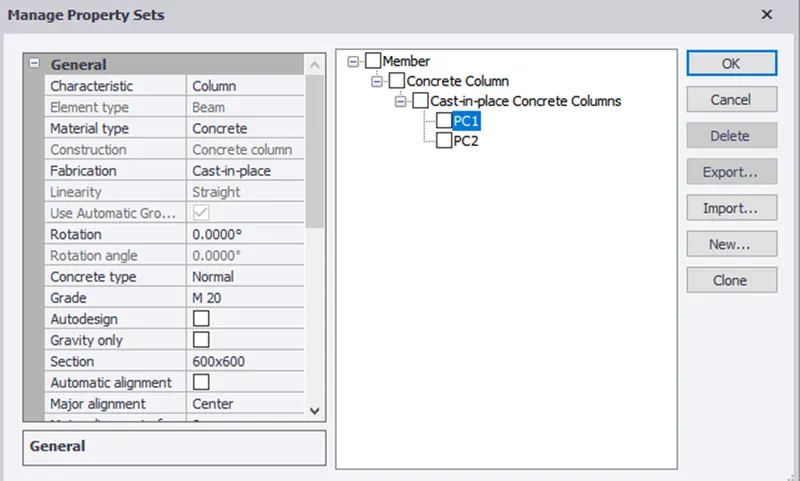
- Now to add Pedestal columns in the Home menu click on Manage property sets options and the manage property sets dialogue box appears.Click on New followed by members and select concrete column.Rename the column for our own convenience and apply the properties as required on the side.
- Now using the column option in the ribbon tab under the model menu columns was placed at locations as required. Columns was placed at base floor and till ground floor
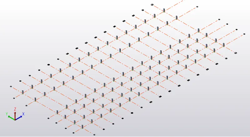
- In the similar way concrete column was created steel columns was created and was renamed as C1.
Now using the column option in the ribbon tab under the model menu columns was placed at locations as required. Columns was placed at ground floor and till top roof.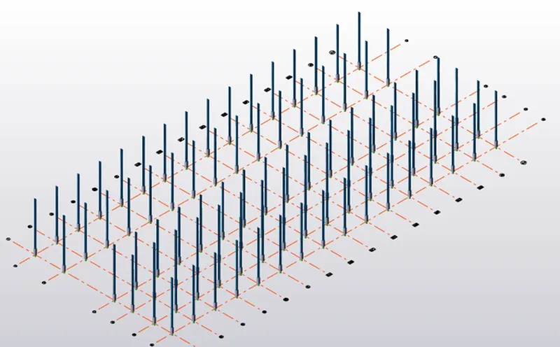
- In the similar way concrete column was created steel beams was created.
- Now using the beam option in the ribbon tab under the model menu beams was placed at locations as required.
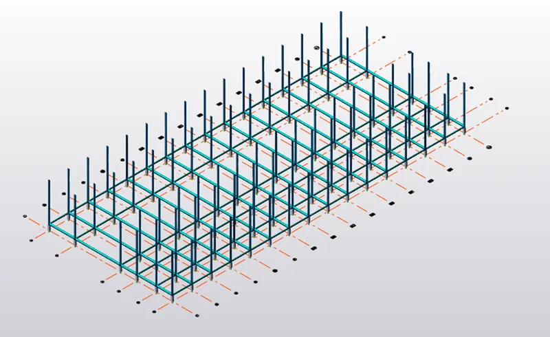
- Rafter beams was designed next for that click on Manage property sets options and the manage property sets dialogue box appears. Click on New followed by members and select Steel Beam. Rename the beam for our own convenience and apply the properties as required on the side.
Now the rafter beams were applied using the Beam option in the ribbon tab under the model menu and beams was placed at locations as required.
The rafter beam releases was set to fully fixed at both the ends for both rafter beams.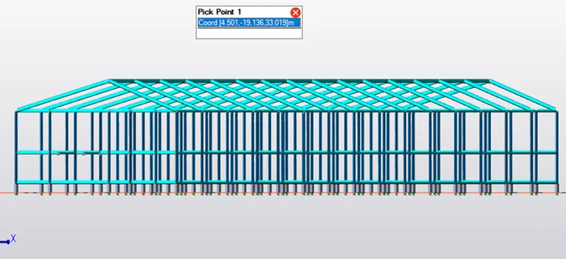
- Steel Bracings was designed next for that click on Manage property sets options and the manage property sets dialogue box appears. Click on New followed by members and select Steel Brace. Rename the beam for our own convenience and apply the properties as required on the side.
Section of size ISA 70X70X10 was chosen for designing the brace.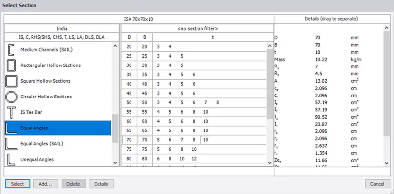
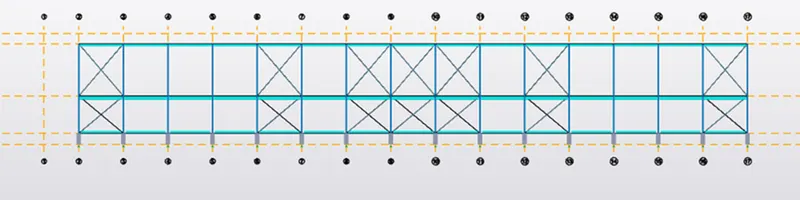
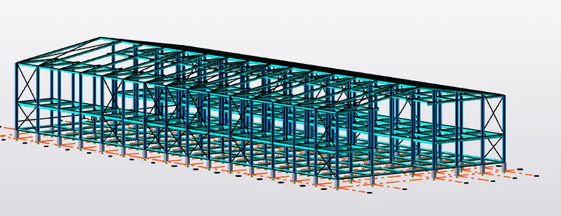
- Now the steel braces were applied using the Brace option in the ribbon tab under the model menu and braces was placed at locations by selecting 2 opposite corner points. X Brace option was selected and drawn. For convenience the braces as drawn on frames on both sides
- Slab properties was designed next for that click on Manage property sets options and the manage property sets dialogue box appears. Click on New followed by members and select Slabs followed by general slab item. Rename the slab for our own convenience and apply the properties as required on the side.Now using the slab on beam option in model menu the slabs was applied on all floors the ground floor, intermediate floor and roof level too.
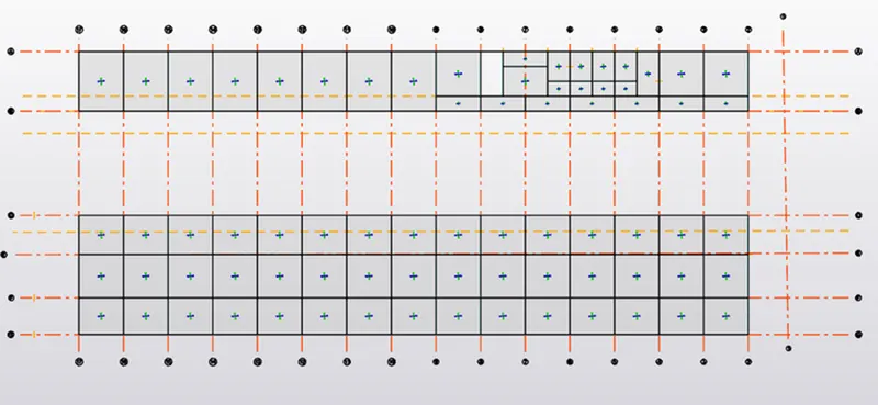
Brackets was defined to carry the crane load and was modelled on the first floor.
- For distributing loads the wall panels was applied to the column using the wall panel option from the model menu.
In the same manner the wall panel was applied to the opposite columns as shown.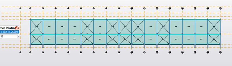
In the same way wall panels was made next the roof panels were created and it is also used for distribution of the load and 3D view of the same is a shown.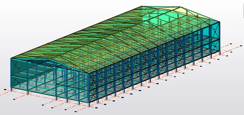
Load Calculations:
|
Initially based on IS 875 part I, all the dead loads in the steel structure were calculated as follows Unit weight of concrete 24 Finish loading- 0.05x24 = 1.2 Brick wall load, unit weight 20 Brick wall loading (GF-IF) O.15*20*5=15kN/m Brick wall loading (IF-R) 0.15*20*7=21kN/m Brick wall loading (R-RT) 0.15*20*4.8=14.4kN/m Self-weight of the slab is calculated by software itself Roof loading based on purlin size 1.5kN/ Ceiling loading 0.3kn/ |
- On the Load tab click on load cases option at the top left corner to open the loading dialogue box. It opens with these as the default loadings.
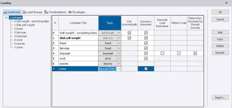
- In order to add new loadings like imposed, wind, seismic and crane loads click on Add option in loading dialogue box and add them and select the type from the drop-down list.
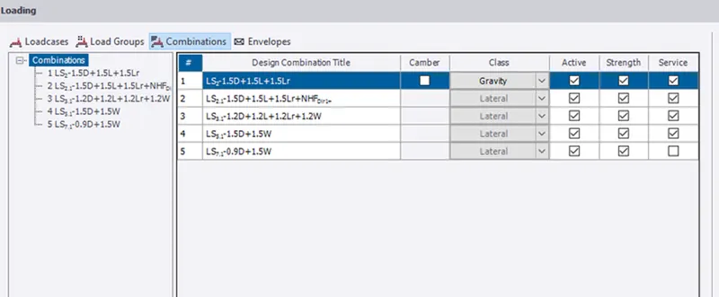
- As we are going to apply the dead loads first select the dead loads option from the drop-down list at the left bottom.
- Open a 2D view (ground floor) of the level within which you want to apply the load.
- In the Loading list, select an appropriate load case.
- On the Load tab, click Area Load.
- In the Properties window, adjust the load details according to your needs (1.2 ).
- Click the panel to which you want to apply the load
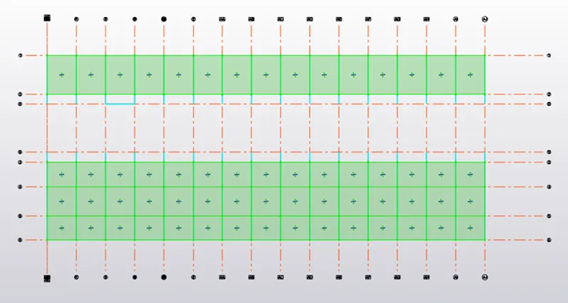
- Loads was applied in all floors and roofs.
For roof load was applied as full UDL.
Wind Load Calculation:
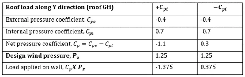
Using the IS 875-3: 2015 the wind load acting on both wall and roof was calculated as shown
|
|
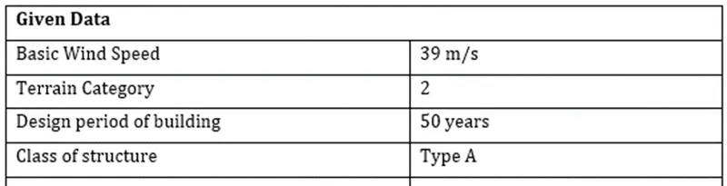
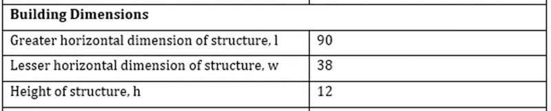
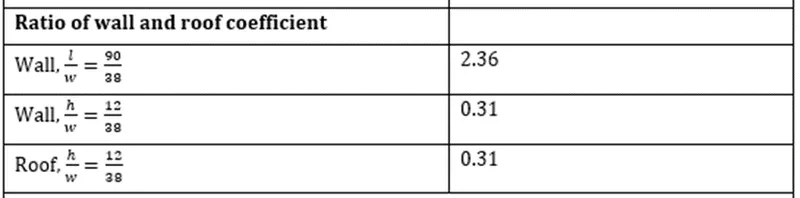
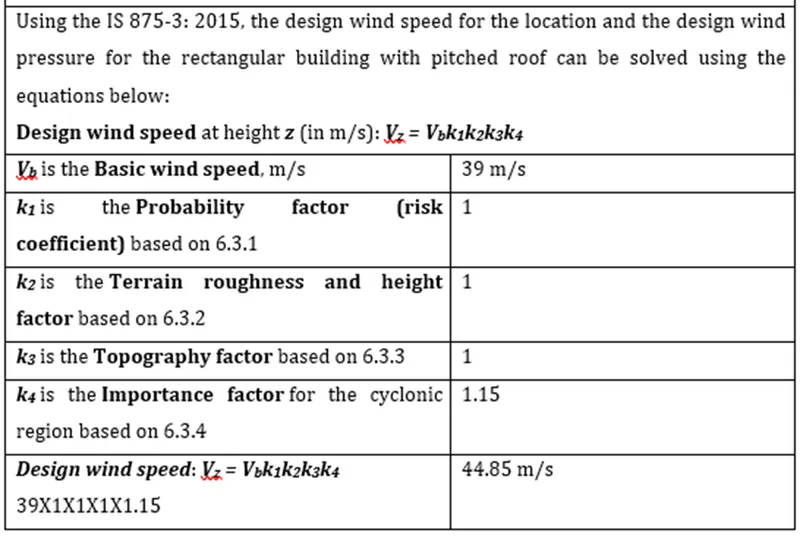
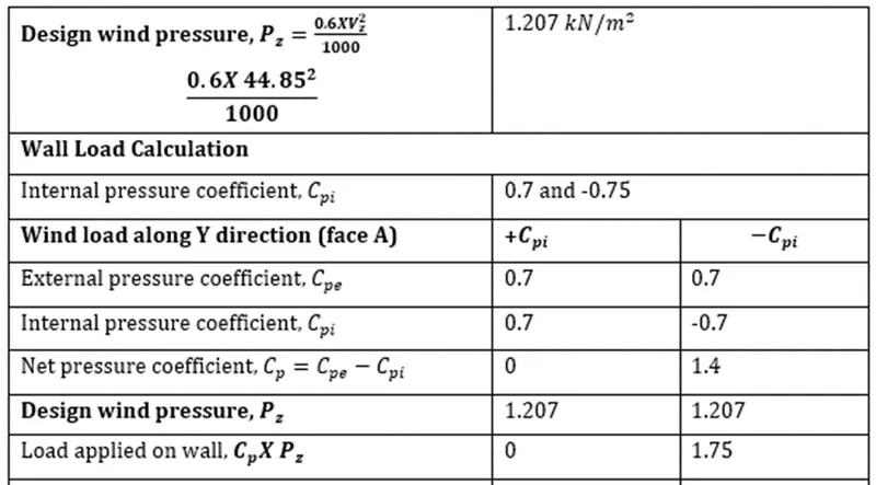
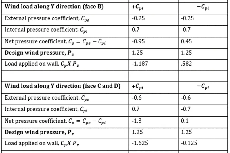
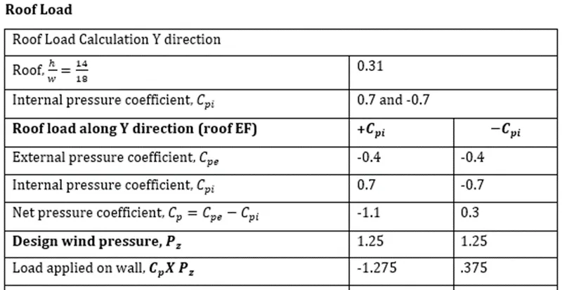
As we are manually applying the wind loads create the new wind load cases by clicking on add option and rename them as shown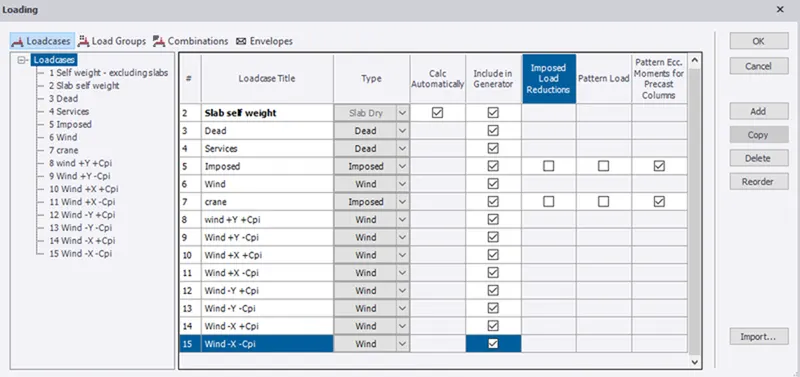
Load case: +Y, +Cpi
Now the wind loads are applied based on the values determined in the calculation. For that initially open the corresponding load case- Wind +Y and +Cpi.
The faces A, B, C and D corresponds to frame 7,3, A and D. Also, the negative value of load implies the load is acting away from building and positive value implies it acts towards the building.
Load case: +Y, -Cpi
The only difference in this from above step is the change in value of Cpi, here the negative Cpi value is considered. The faces A, B, C and D corresponds to frame 7,3, A and D. Also, the negative value of load implies the load is acting away from building and positive value implies it acts towards the building
Similarly, all the loads were applied to both roof and walls as shown.
All the same principles were followed here also while applying the roof load like the roof face EF and GF as well as the positive and negative load values acting towards and away from the building
Crane Load Calculations:
|
|
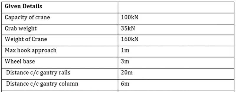
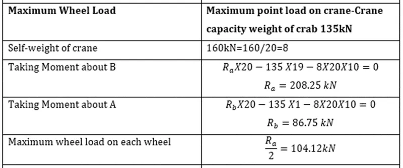
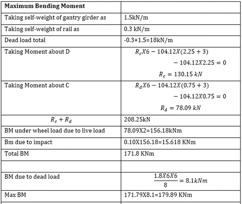
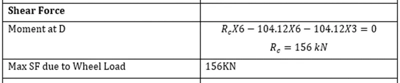
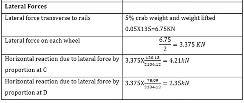
Crane loading was applied to the roof the structure.
Seismic loading was also calculated using the seismic wizard in TSD and after that the model was analyzed (1st order analysis).
After analysis, all the components was adjusted or resized whenever error occurred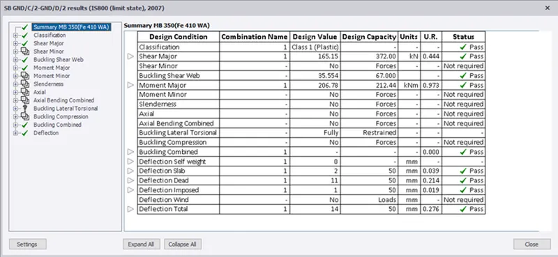
RESULTS:
From the data given the plan was developed sing the TSD software
All loads were calculated and applied on structure
Analysis was performed and members was adjusted upon errors