To calculate wind load for industrial steel structures and to apply it by using TSD
AIM: To calculate wind load for industrial steel structures and to apply it by using TSD
PART I:
To Generate manual wind loading in the design report based IS code as per the following input
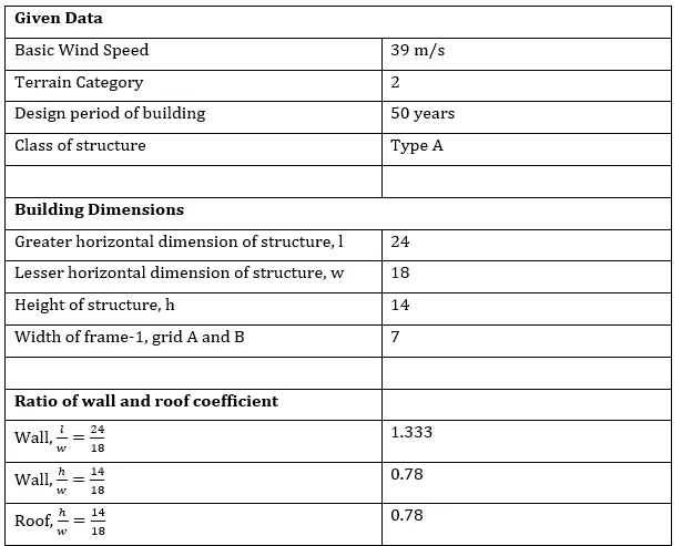
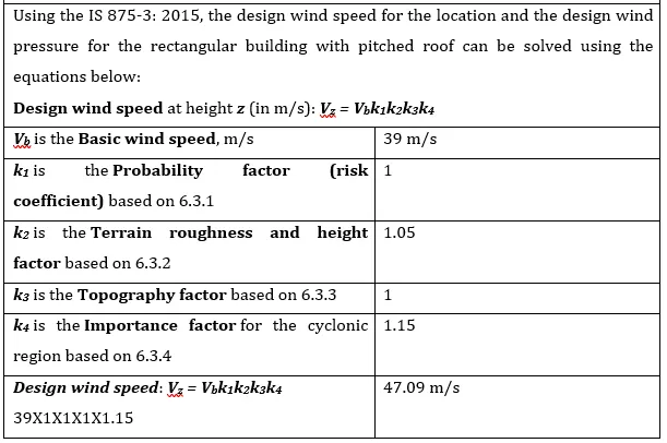
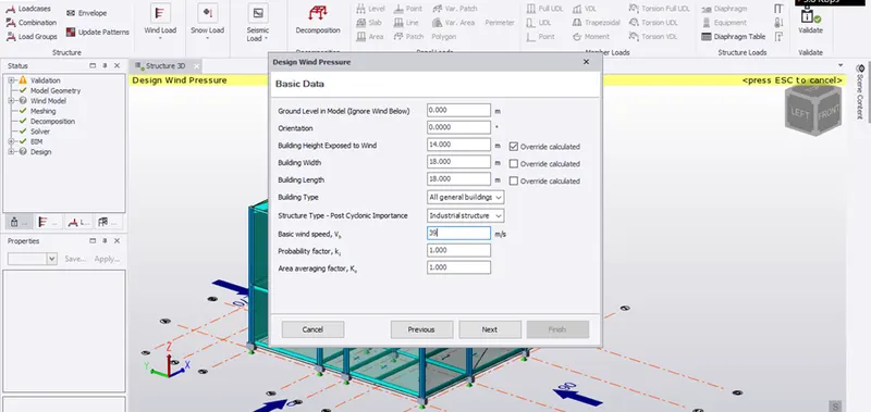
- Basic wind speed = 39 m/s
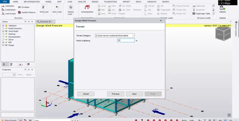
- Terrain category 2
Based on the above calculation apply the loadings on the model
PART II:
On a separate model generate wind loading using wind wizard
INTRODUCTION
As the wind blows against a building, the resulting force acting on the elevations is called the ‘wind load’. The building’s structural design must absorb wind forces safely and efficiently and transfer them to the foundations in order to avoid structural collapse.
When analysing tall buildings using wind engineering, wind is usually found to be the dominant load and is primarily a horizontal force. The structural systems that absorb wind loads tend to be separate to those for dead loads and other gravity loads generated internally to the building.
Wind loads will typically depend on the wind velocity and the shape (and surface) of the building, and is why they can be difficult to predict accurately. The building shape may exacerbate any over- or under-pressure effects. On the windward side (facing the wind), wind overpressures may blow windows in, while on the leeward side (sheltered from the wind) under-pressure (suction) may blow windows out. A glass-clad building with a very smooth profile will tend to deflect the wind far more effectively than a sculpted or textured profile, as will a circular building compared to a square shape.
Buildings, especially if they are super tall (over 250m high) are usually designed to withstand very strong winds, taking into account factors such as design wind speed – which will depend on location and meteorological records (average wind velocities). Tall buildings may resolve wind forces by transferring them through their floorplates to the structural core, and then down to the foundations.
Procedure:
PART I and II:
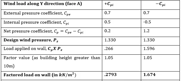
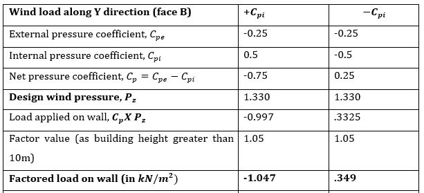
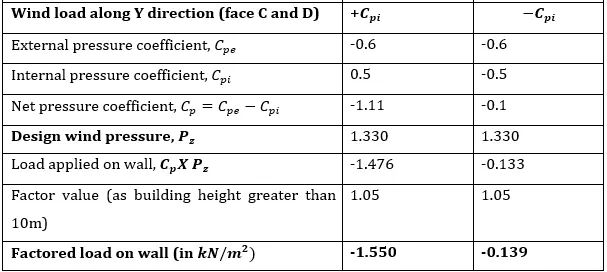
- Open the last saved file of Tekla and click on Load cases option under the Load tab.
As we are manually applying the wind loads create the new wind load cases by clicking on add option and rename them as shown
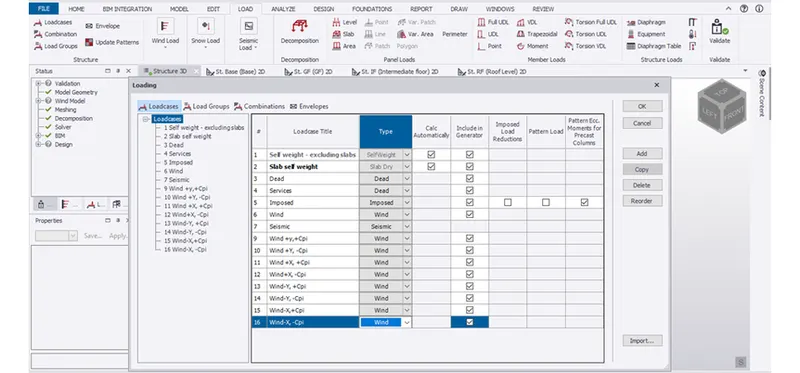
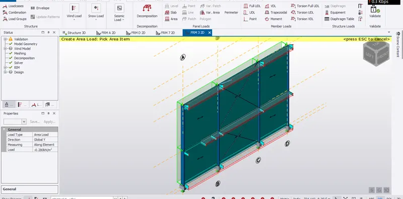
Now the wind loads are applied based on the values determined in the calculation. For that initially open the corresponding load case- Wind +Y and +Cpi.
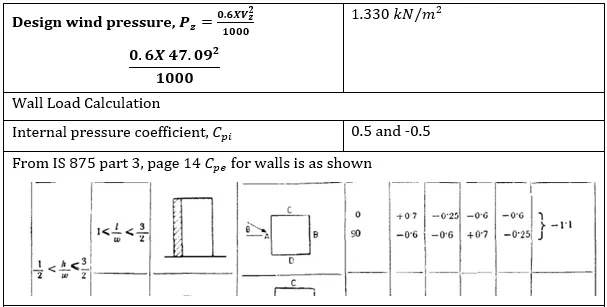
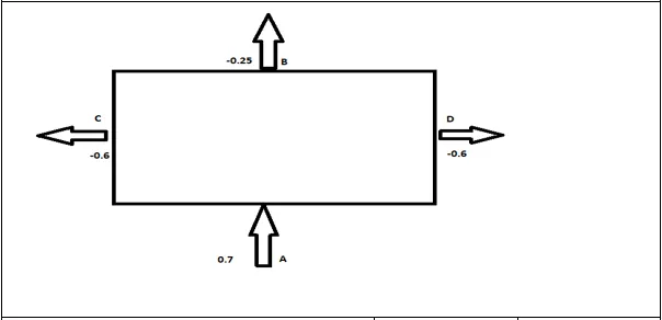
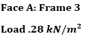
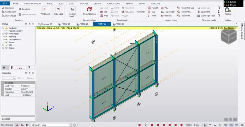
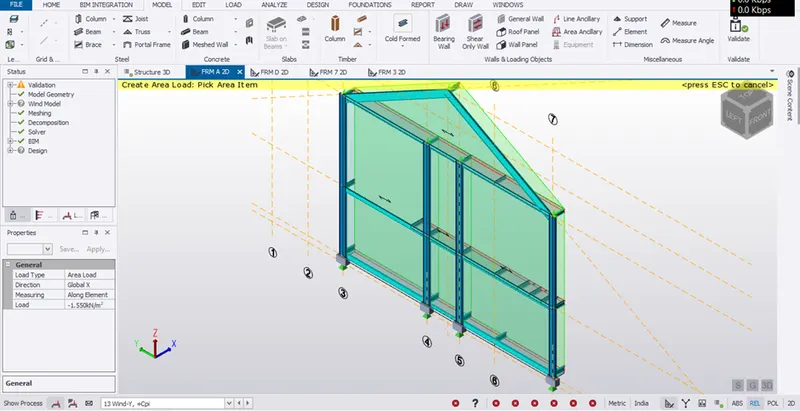
The faces A, B, C and D corresponds to frame 7,3, A and D. Also, the negative value of load implies the load is acting away from building and positive value implies it acts towards the building

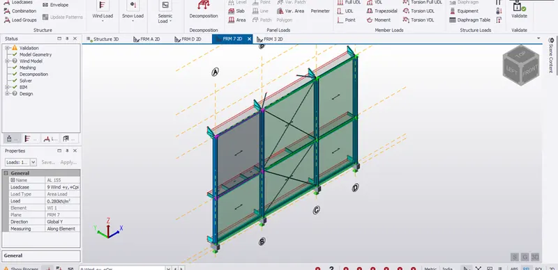

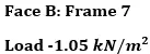
Negative sign indicates the load is to be directed away from the building. This load is to be applied on face B that is on frame 3.
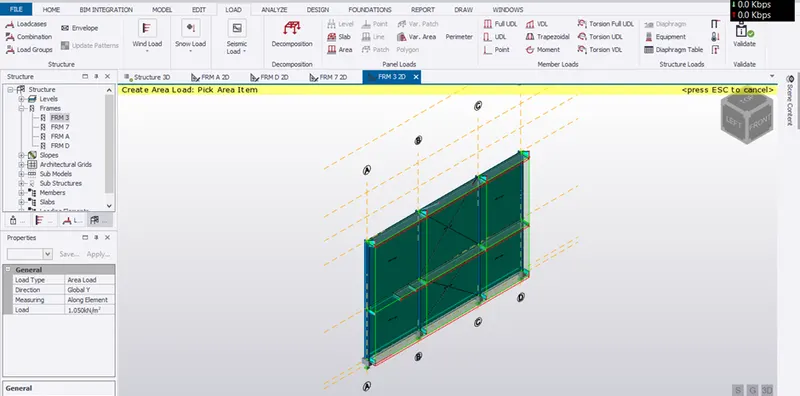

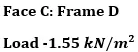
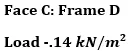
Negative sign indicates the load is to be directed away from the building. This load is to be applied on face c that is on frame A
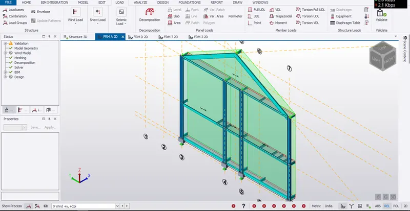

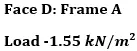
Negative sign indicates the load is to be directed away from the building. This load is to be applied on face D that is on frame 3.
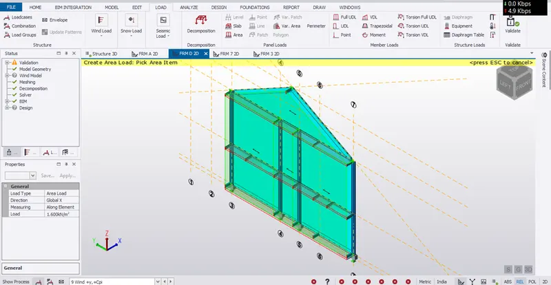
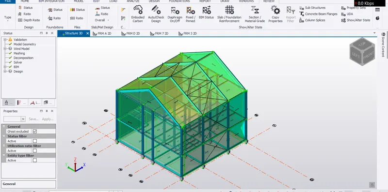
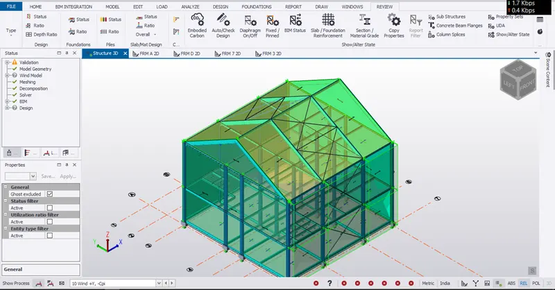
The 3D view of the structure in which all wind loadings (+Y, +Cpi) have been applied is as shown below.
Load case: +Y, -Cpi
The only difference in this from above step is the change in value of Cpi, here the negative Cpi value is considered. The faces A, B, C and D corresponds to frame 7,3, A and D. Also, the negative value of load implies the load is acting away from building and positive value implies it acts towards the building
Face A: Frame 7

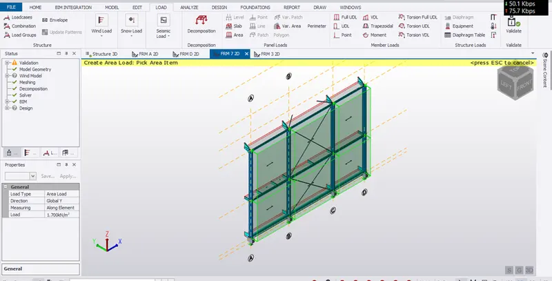
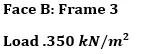
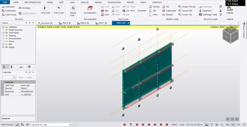
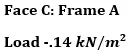
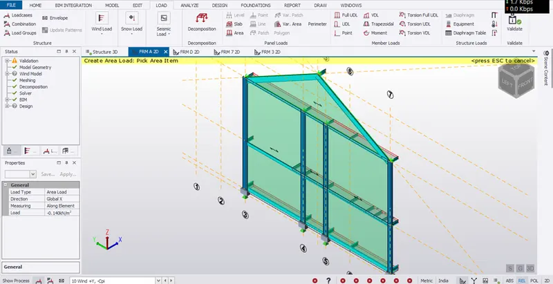
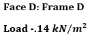
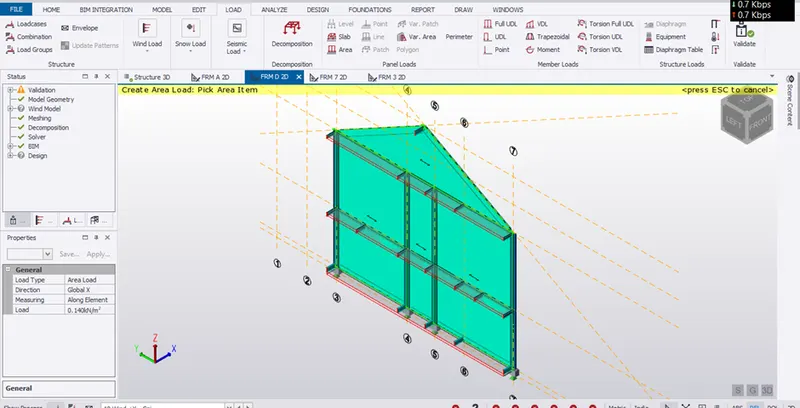
The 3D view of the structure in which all wind loadings (+Y, -Cpi) have been applied is as shown below.
Load case: -Y, +Cpi
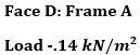
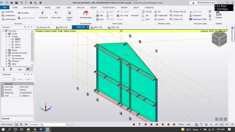
The only difference in this from above +Y loading is the change in direction of face. The faces A, B, C and D corresponds to frame 3, 7, D and A. Rest load application process is the same
 .
.
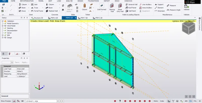
The 3D view of the structure in which all wind loadings (-Y, +Cpi) have been applied is as shown below.
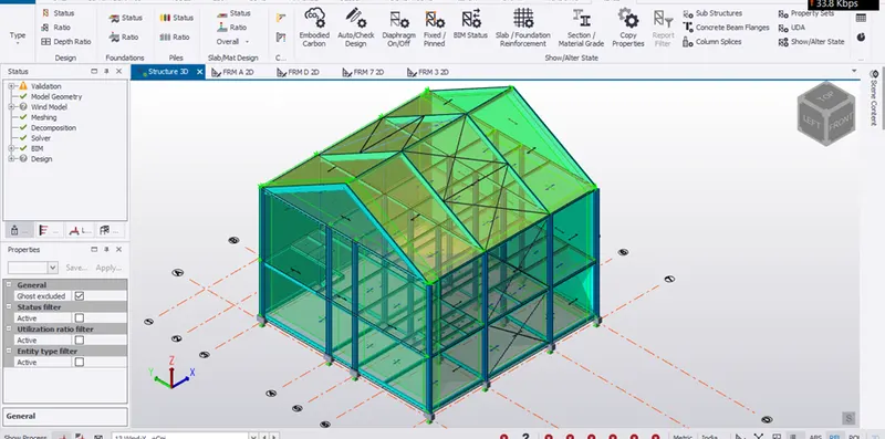
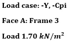
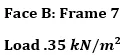
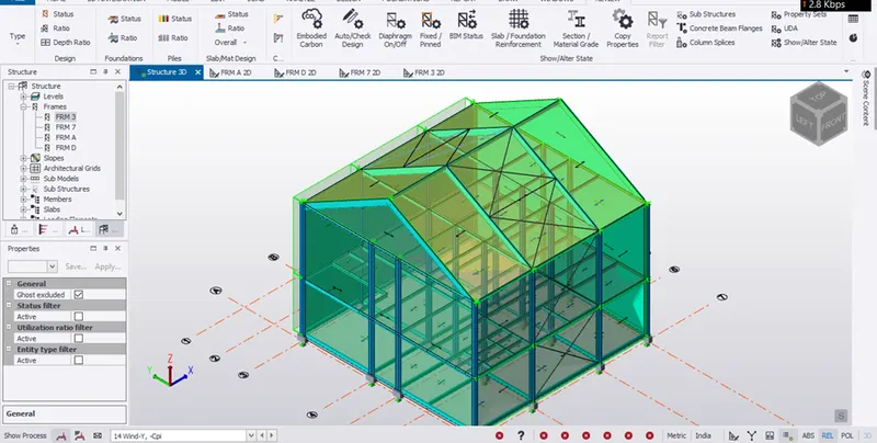
The 3D view of the structure in which all wind loadings (-Y, -Cpi) have been applied is as shown below.
The same manner in which +Y and -Y load cases are applied the corresponding +X and -X wind loadings are calculated and applied next.
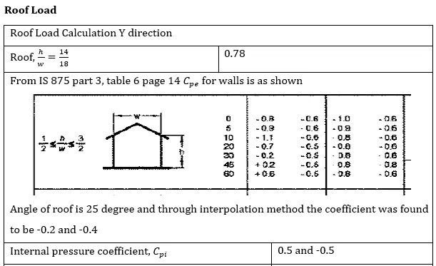
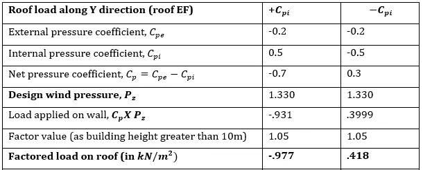
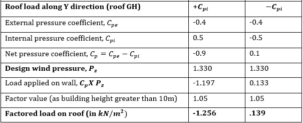
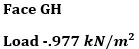
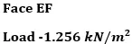
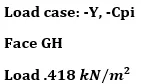
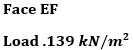
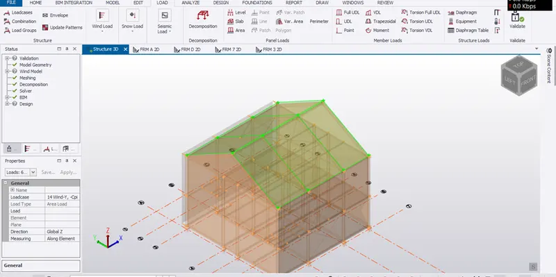
All the same principles were followed here also while applying the roof load like the roof face EF and GF as well as the positive and negative load values acting towards and away from the building
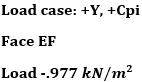
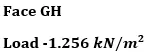
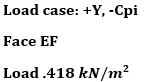
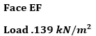
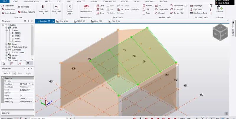
Load case: -Y, +Cpi
In the -Y load case + Cpi loads will be applied to face GH and -Cpi load will be applied to face EF just the reverse of +Y load case
Validation
X axis calculations:
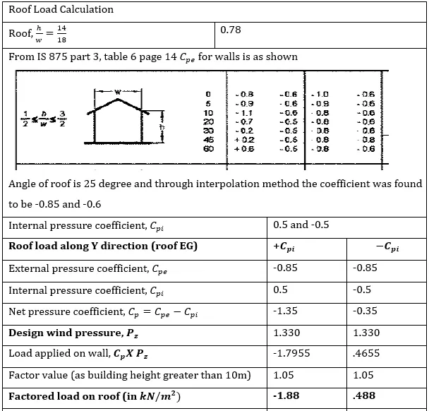
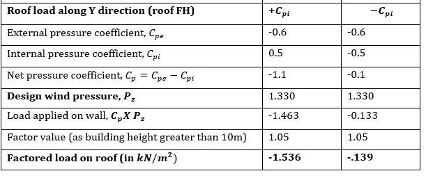
In the similar fashion load was applied in Y direction, The loads are applied in the X direction too.
PART III
Now open Tekla file in which no manual wind loads were applied, In the Load tab click on Wind load followed by wind wizard to open the design wind pressure dialogue box.
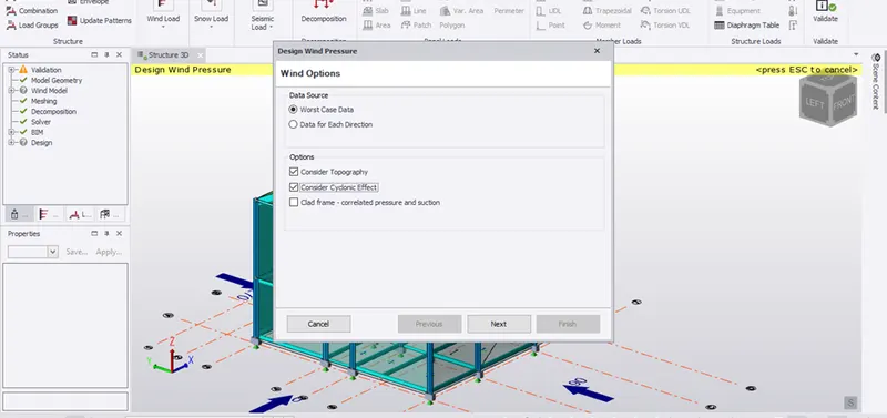
Select the desired wind options from the menu below and click next.
Now confirm the basic details of steel building like the dimensions, wind speed and various factors etc. and click next.
Select the desired terrain category from the drop-down list and click next.
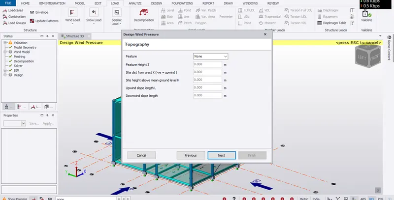
In topography if needed apply the desired values and click next.
Next the results will be shown as below
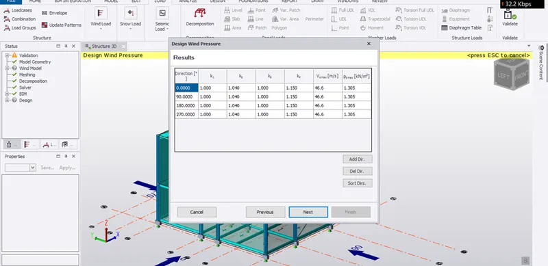
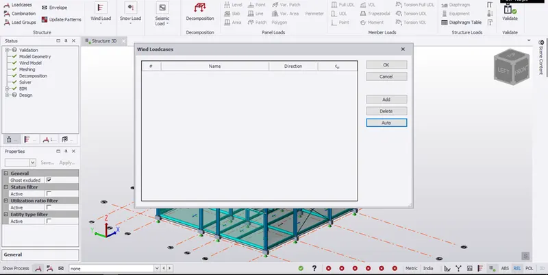
In the Load tab click on Wind load followed by wind load cases to open the design wind load cases dialogue box.
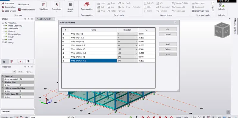
Now define the desired wind loads in all directions as shown
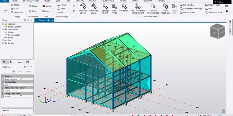
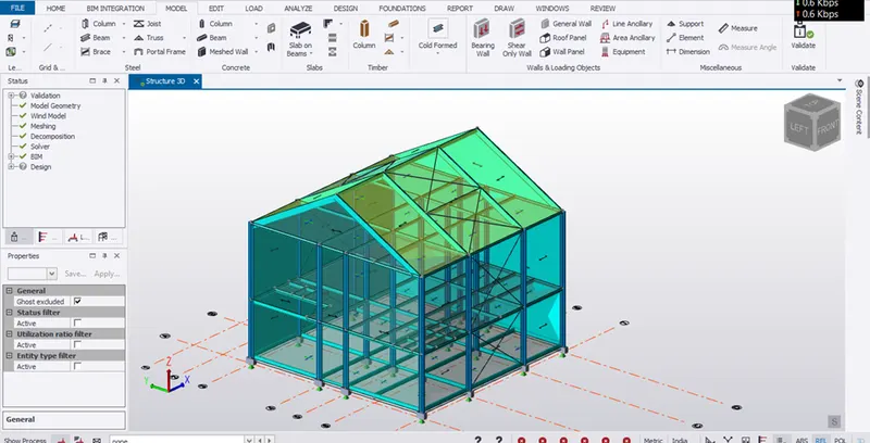
The model was validated to check for any errors.
Results:
Wind loads and roof loads was calculated based on IS 875 Part III.
The wind load and roof load calculated was applied to the steel structure.
And finally on a separate model wind load was calculated using the Tekla software’s wind wizard