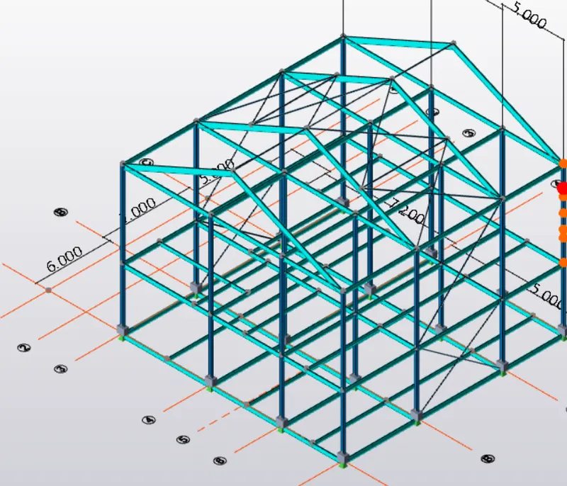
To model beams and bracings for industrial steel structures using TSD
Aim: Create beam properties for first floor and model the beams
Procedure:
Step 1
- Open TDS
- Open the challenge 2 file
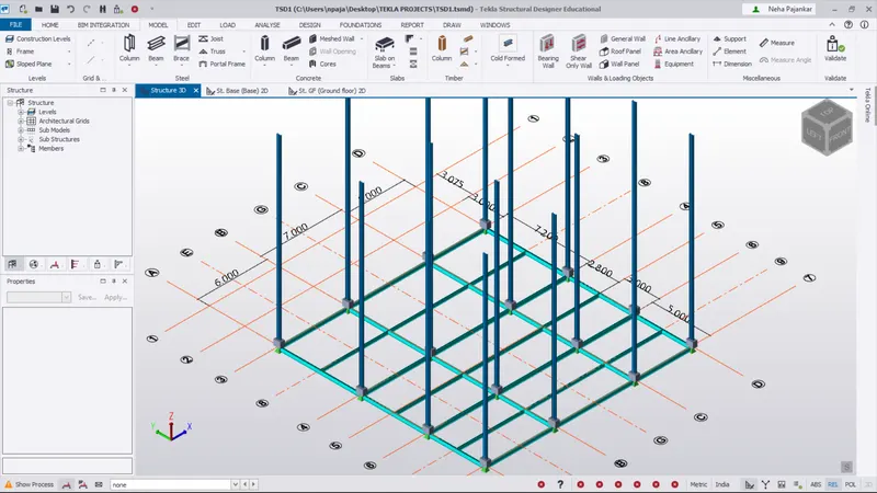
Step 2
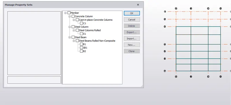
- Go to home tab and click on manage properties
- Click on new and add new steel beam member
- Edit the properties and rename it.
Step 3
- Go to stuructural window in left of screen
- Click on first floor
- Go to model tab and click on steel beams and in properties section click on desired beam property
- Apply the beams on the grids attached to columns
Step 4
- To create secondary beams go to home tab < new < member < steel beam
- Specify required changes and rename it
- Now go to first floor level
- Apply the secondary beams
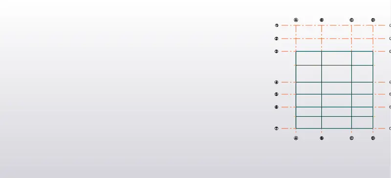
Result: With this our objective is completed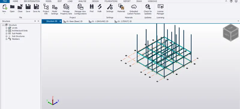
2. Aim: Create rafter beam on second floor as roof and moment frame action in one direction and add bracings at location as per design intent
Procedure:
- Continue the work on the same file above
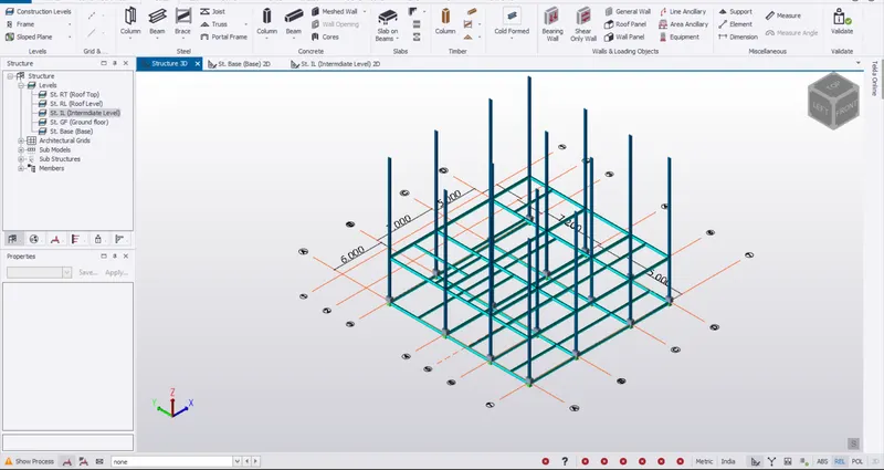
- Go to roof level
- Only primary beams are designed on this floor due to loading capacity
- Use the same beam patterns used in first floor
- Go to model section and select steel beam
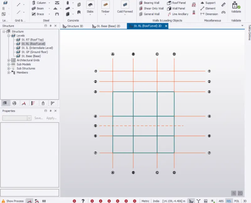
- Select same beam properties used in first floor and start creating the beam on grids are required
- Change the column height to roof level
- Go to scene content and uncheck others so that only columns are visible
- Select all columns and go to property window< top level
- Change the constraint to roof level and apply
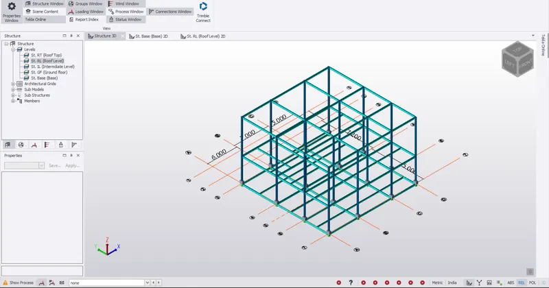
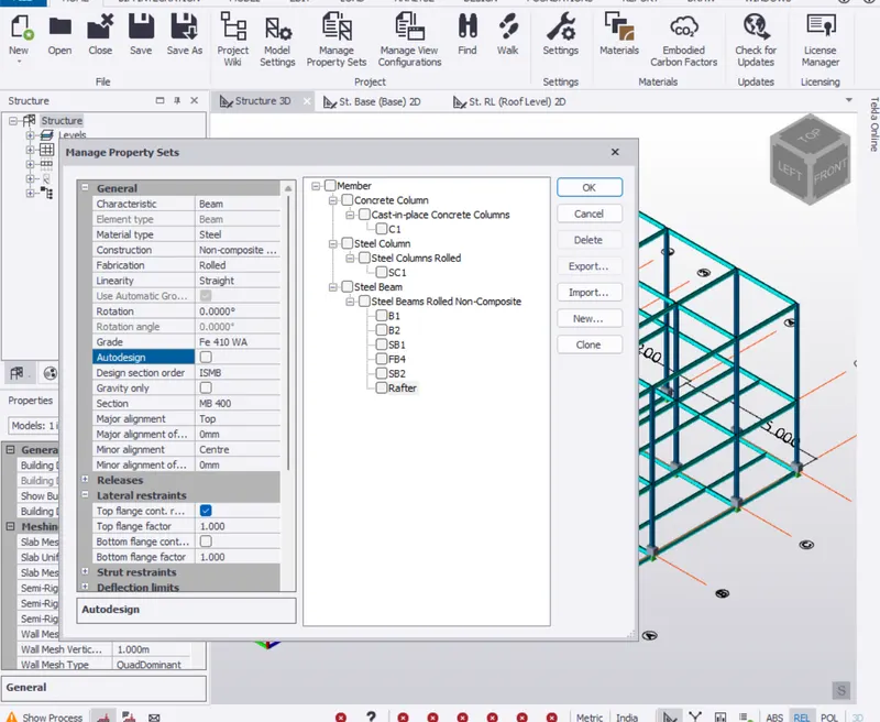
- Go to home page and create a new propertyset < new < member < steel beams
- Input the properties and rename it
- Now create frame
- Go to model < frame < select the grid line where you want to create frame
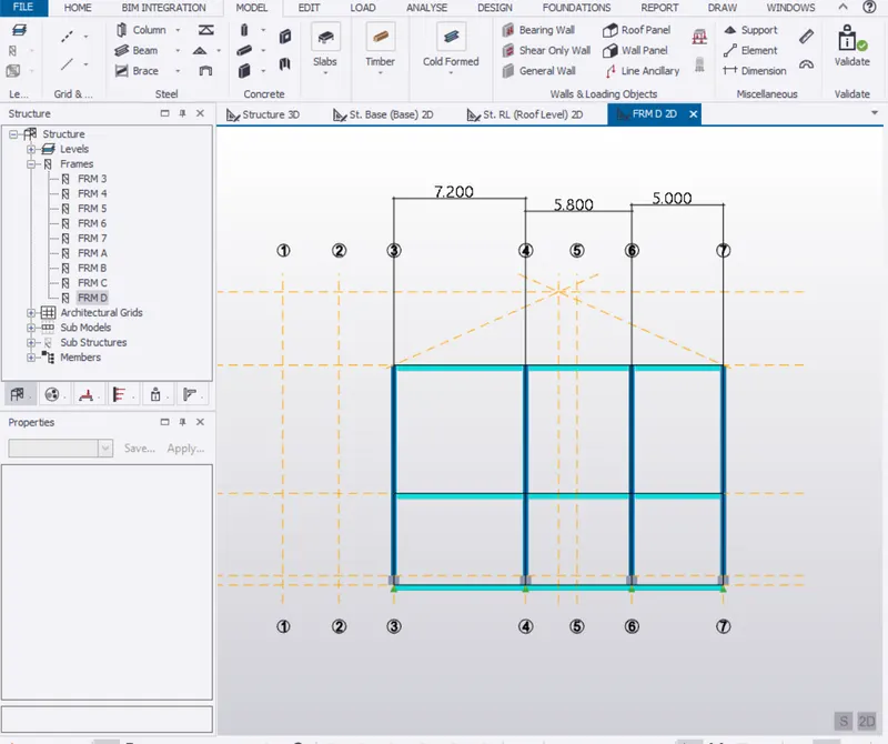
- Now go to frame D < create a construction line for rafter intersecting at mid height
- Now go to model section < steel beam < select rafter property < draw intersecting line
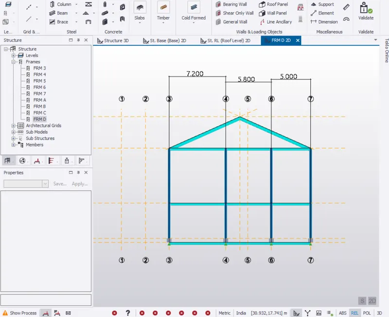
- Now go to create rafter on other column
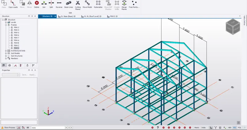
- Select rafter < go to edit < copy < select reference point < select placing point and enter
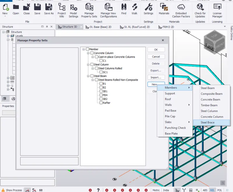
- Design of steel bracing: Go to home < manage property set < new < menber < steel brace
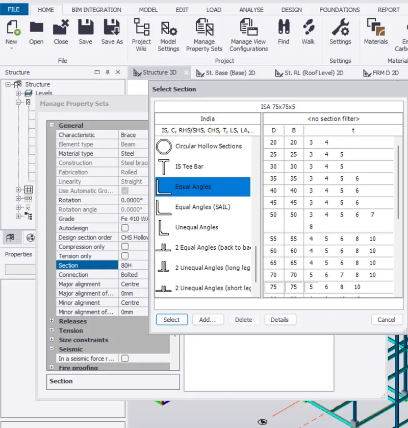
- Select the section < equal angle (75x75x8)
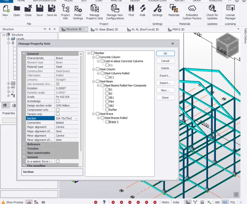
- Rename it and make the necessary changes
- Go to model tab < braces < select brace from the property browser
- From the brace panel select the X brace
- Open the frame 7 to view the section and draw the braces on the frame
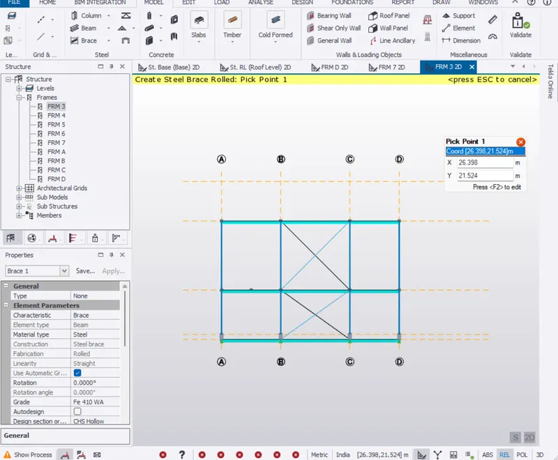
- Similarly put the braces on the other required positions
- See the 3D view for better visulazation
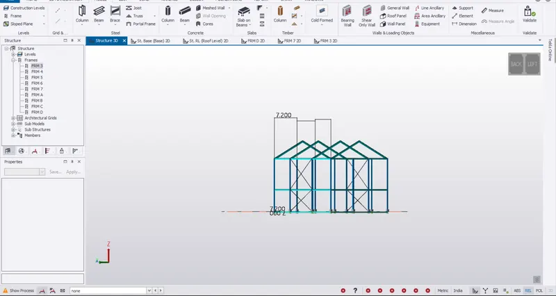
- Draw the braces on the roof top.
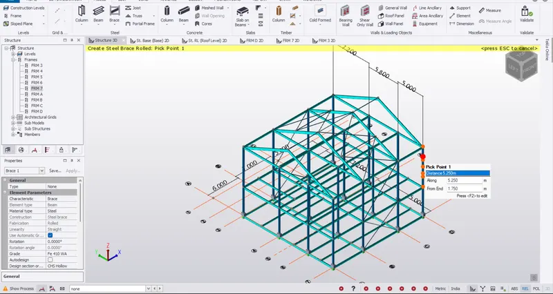
Result: Creation of rafter beam is completed on structure