Hood design-Week 2
Objective:
To Design hood outer panel, inner panel and reinforcements with the given outer hood skin, master section and design parameters.
Introduction:
HOOD
The hood or bonnet is a hinged cover over the engine of motor vehicles that allows access to the engine compartment, or trunk for maintenance and repair. The inner panel provides strength while the outer panel functions as the metal cover and a aesthetic surface for the look of the vehicle.
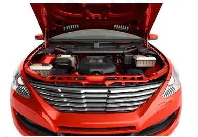
Figure 1 :Hood of a car in open condition
Hood stay is an apparatus for supporting the engine hood of a vehicle in its open position. Common types of hood stays are Support Rod and Gas Stay. Support rods are manually operated and they are cost effective and simple to design whereas gas stays require no man power but they are costly which is powered hydraulics.
Design Consideration
The hood should meet some specific conditions like pedestrian safety, hood head zone for the lock striker, force distribution when subjected to frontal collision (occupant safety), manufacturability , cost of production etc.
Euro NCAP or The European New Car Assessment Programme is a European voluntary car safety performance assessment programme which test vehicle Safety and Crash worthiness.
On the bass of this rating and standard, the hood is designed to such a way that it crumbles and takes all the impact providing safety for the occupant as well as pedestrian head impact for adult and child standards.
Design Parameters
Hood Thickness Information
- Outer Panel Thickness = 0.75mm
- Inner Panel Thickness = 0.75mm
- Reinforcement Thickness = 1.5mm
Master Section
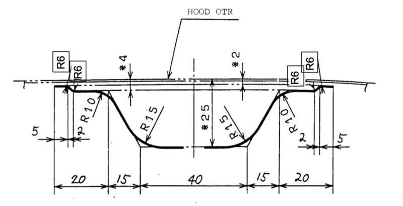
Components of Hood Panel
The Hood consists of inner panel, outer panel , hinge reinforcement , Striker reinforcement as shown below in the figure in detail
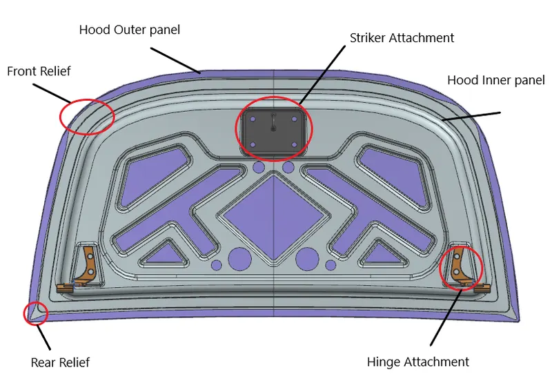
Fig 2: Final Hood design with Reinforcements
Hood are typically made out of the same material as the rest of the bodywork. This may include steel and aluminium. Deep drawing, hemming, blanking and piercing are the common sheet metal operations that are used in manufacturing hoods in automotive industries.
Maufacturing Process
Hemming
Hemming is a forming operation in which the edges of the sheet are folded or folded over another part in order to achieve a tight fit. Normally hemming operations are used to connect parts together, to improve the appearance of a part and to reinforce part edges.
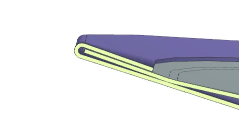
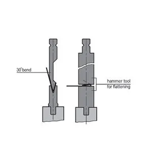
Fig 3: Hemming of outer panel with inner panel
The accuracy of the hemming operation is very important since it affects the appearance of the surface and surface quality. Material deformations, which occur during the hemming process, can lead to dimensional variations and other defects in parts. Typical hemming defects are splits or wrinkles in the flange, material overlaps in the corner areas or material roll-in. This is why it is important to provide required reliefs at the corners.
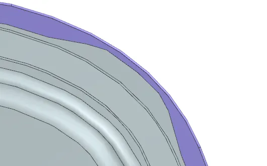
Fig 4: Front Relief
There are two types of hemming operations,
- Conventional die hemming
In conventional die hemming, the flange is folded over the entire length with a hemming tool.
- Roll hemming
It is the roll hemming process that is used for automotive sheet metals. Roll hemming is carried out incrementally with a hemming roller. An industrial robot guides the hemming roller and forms the flange. Roll hemming operation can also be divided into several pre-hemming and final hemming process steps. Roll hemming is very flexible to use and tool costs are significantly lower as compared to those of conventional die hemming. However, the cycle times are much higher since the hemming is realized using a hemming roller which follows a defined path.
Deep Drawing
In this Manufacturing process, Sheet metal blank is radially drawn into a forming die by the mechanical action of a punch. It is thus a shape transformation process with material retention. The process is considered "deep" drawing when the depth of the drawn part exceeds its diameter. This is achieved by redrawing the part through a series of dies. The flange region (sheet metal in the die shoulder area) experiences a radial drawing stress and a tangential compressive stress due to the material retention property. These compressive stresses (hoop stresses) result in flange wrinkles. Wrinkles can be prevented by using a blank holder, the function of which is to facilitate controlled material flow into the die radius.
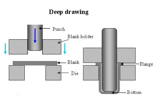
Fig 5: Deep drawing Process
Embossing
Sheet metal embossing is a stamping process for producing raised or sunken designs or relief in sheet metal. This process can be made by means of matched male and female roller dies, or by passing sheet or a strip of metal between rolls of the desired pattern
In this design, Emboss is created to reduce weight of the panel, decrease material use and provide better collison support dissipating the force in a crash.
Also here , Embosses are created with draft angle of 10 degrees for easy maufacturing.
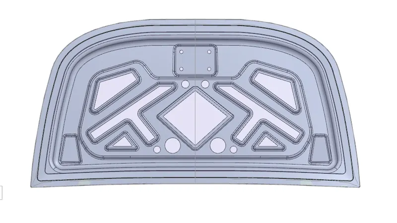
Fig 6: Emboss of inner panel
Mastic Sealant
The Hood commonly possesses large surface area and hemming can only be provided through its boundary. We cannot use other joining techniques like welding, riveting etc because they leave marks on the outer panel which spoil its aesthetic appearance.
Mastic sealants are elastic compounds that behave like rubber. So, the mastic sealants are used to stick the inner surfaces of the outer panel and inner panel.
It is applied between the inner and outer panels in the embossed cut out at specified spots in the center. Each spot of mastic sealants has its effect around a circular region of 80mm diameter. Thus, the mastic points are arranged in such a way that it covers the areas away from the hemming which are more vulnerable to vibrate.
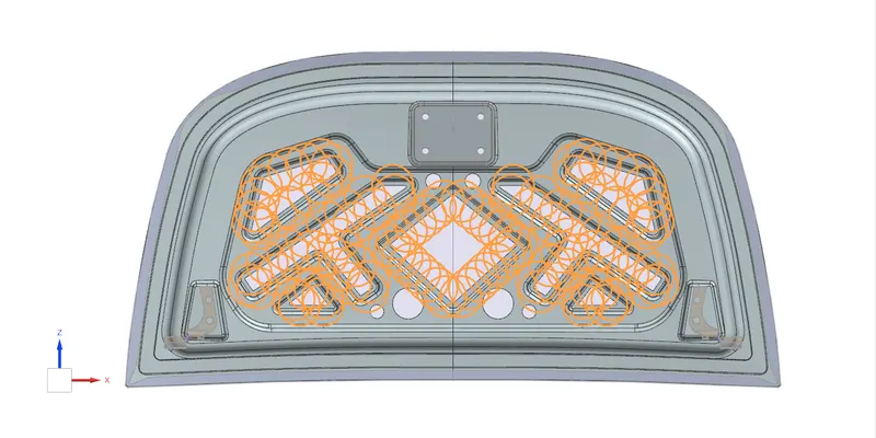
Fig 7: Mastic Data of the hood
Final Assembly
Latch trajectory
In this assembly, First Hinges are constrained with the Hood panel by creating hinge axis line and then a circle is drawn with center point of the hinge axis to be the Striker Latch Attachement reference and its trajectory. It is done to place the tip of the latch to be in place with the trajectory circle for proper mating condtion as shown below.
The latch Trajectory is also the Trajectory of movement of the whole Hood panel which mates and closes with the engine compartment body.
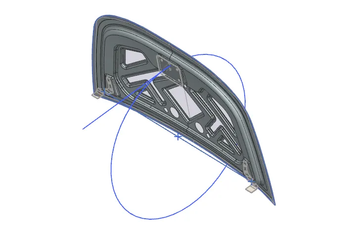
Fig 8: Latch Trajectory
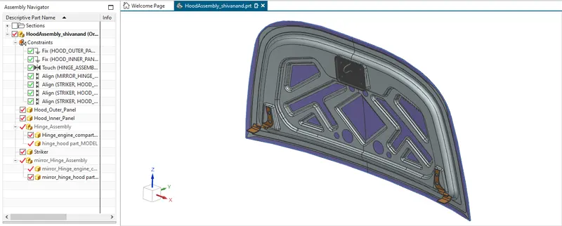
Fig 9: Final Design & Assembly of the Hood panel
Conclusion
- The design is made by Top-down approach (i.e assembling the parts and then working on designing the parts).
- Safety consideration of EuroNCAP standards were subjected while desiging the inner panel.
- Design is produced with mastic data references and other attachment features from the given Hood skin and master section.