Week 9 - Attachment Feature Creation - Challenge 1
ISOMETRIC VIEW
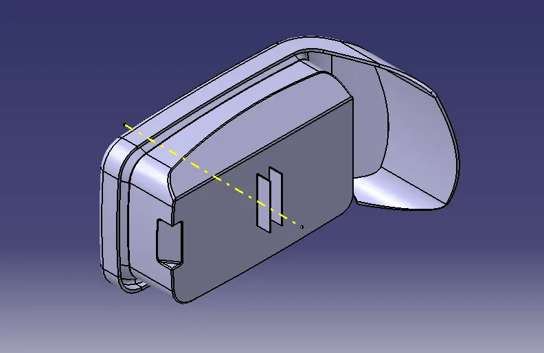
All the design rules are met while creating the ribs it shown in detail below.
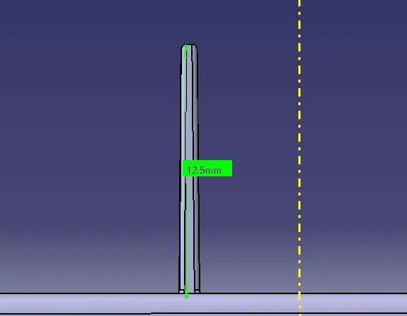
12.5 mm is the maximum height the rib can be and it is followed as given.
Minimum thickness at the top
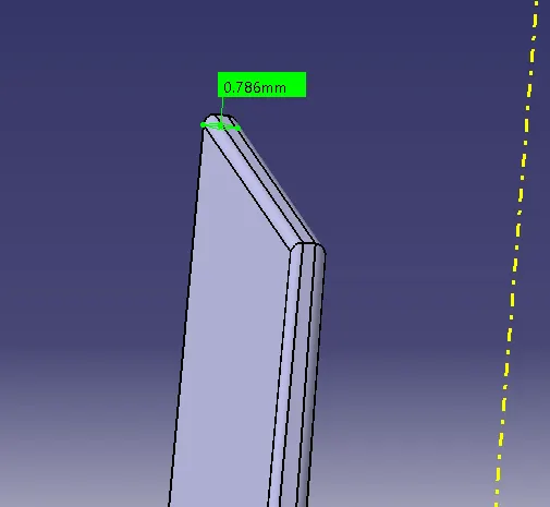
Minimum thickness is 0.75mm and this design has cleared the minimum thickness.
Minimum thickness at the base (overall)
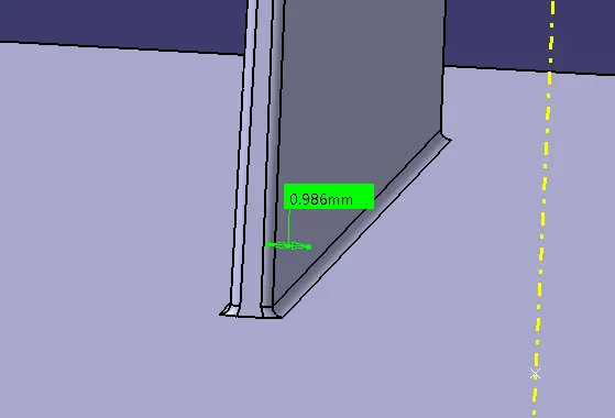
Minimum thickness should be 0.4 times the thickness of the component (2.5mm). Hence 1mm is minimum thickness and the rib is thickened accordingly.
Radius of the RIB Fillet
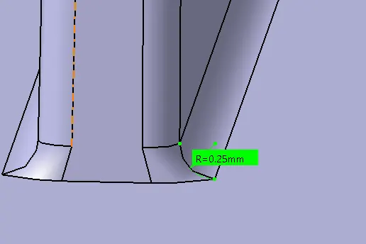
Optimum radius is 0.25mm of the fillet joining the component.
RIB Root thickness
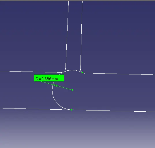
Rib root thickness should be 30% more than the thickness of the component. Here 2.6mm > 0.75mm.
Draft Angle
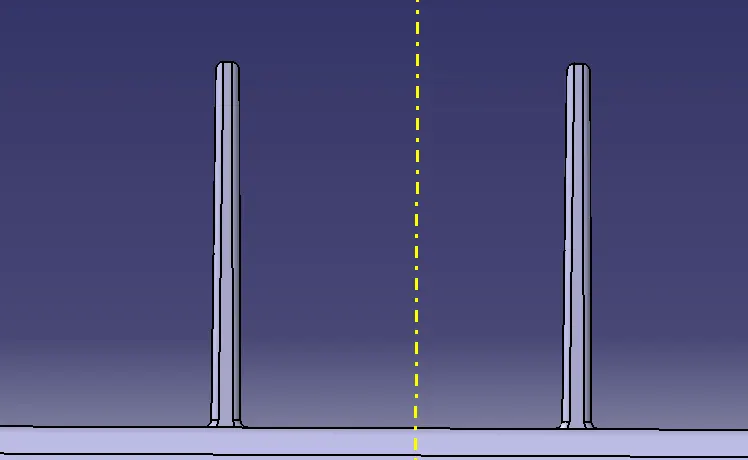
Minimum draft angle is 0.5 degree which is given to the Ribs.
Distance between the Ribs
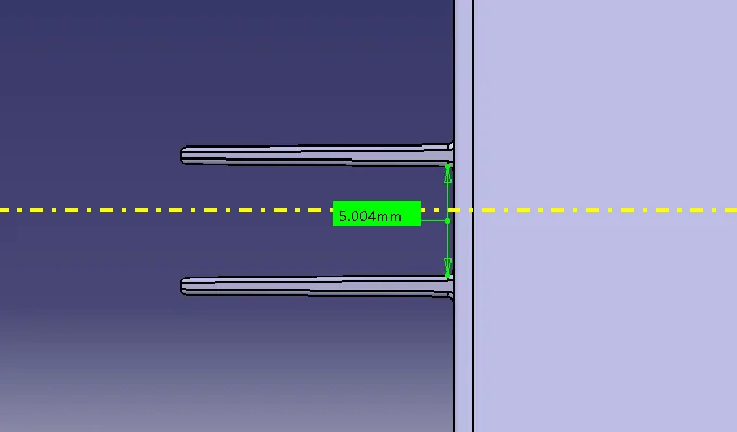
Spacing between the ribs is done on the ratio of 3:1.
DRAFT ANALYSIS
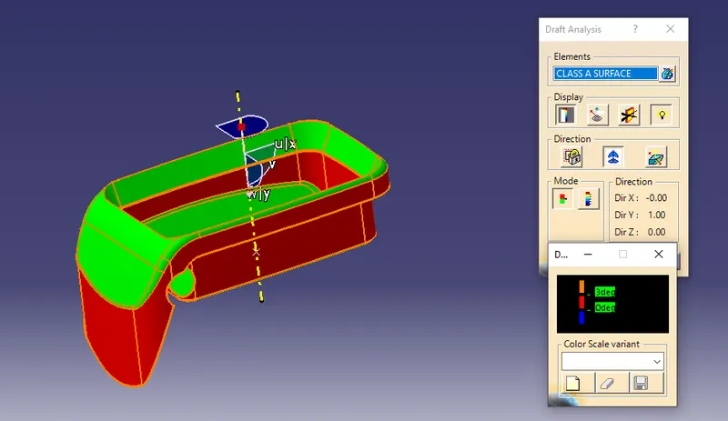
Tooling axis is created perpendicular to the base surface of the pocket as it is the obvious direction of a tooling in manufacturing.
Since single tooling axis is not enough for clearing the draft angle of the side walls, Sliders and lifters along the main core in the time of manufacturing should be used with its own tooling axis to give draft angle for the failing features.
Addting sliders, side core, lifters etc. increase the expense of the manufacturing process which is not advisable.