Fender Design Challenge
Objective:
To design the car front fender with the help of using skin data (Class A surface) shared by the styling team and make it ready for manufacturing with mounting flanges using NX CAD
Introduction:
Fender:
Fender is a part of the vehicle that frames the wheel . The primary purpose of the fender is to prevent sand , mud , rock etc from being thrown away into the air by rotating tire and harm pedestrians.

(car front fender)
There is two types of fender in a car body, front fender and rear fender as shown.
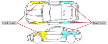
Fender can be of two types , full bumper type and half bumper type . Nowadays half bumper type fender is typically used . the cost of sheet metal blank is reduced as we can produce two half bumper type fender in single blank . This also leads to reduction of scrap.
Design Features of Fender:
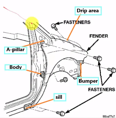
Mounting Area
- Bumper
- Drip
- A Pillar
- Sill
- Cowl
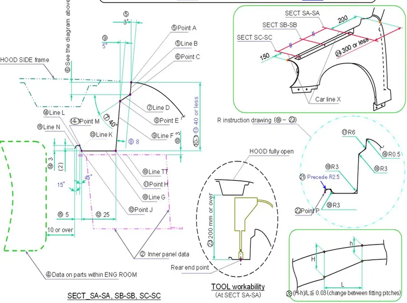
Given master section
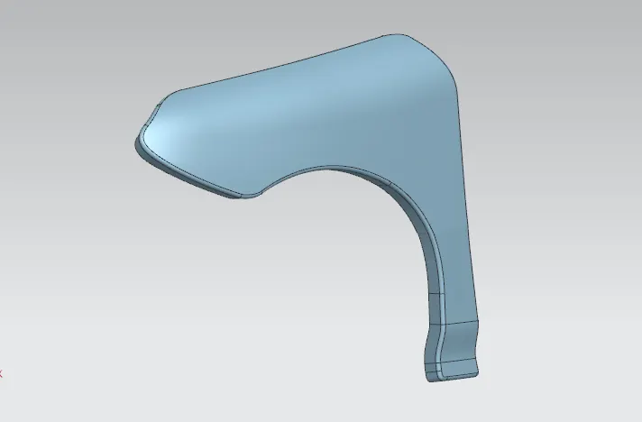
Input skin (Class A surface)
Procedure:
Drip area Design
Drip area mounting is the important part in the fender . This mounting is attached to the engine compartment of the car . Fender drip area is mounted via weldnuts to the engine compartment.
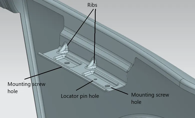
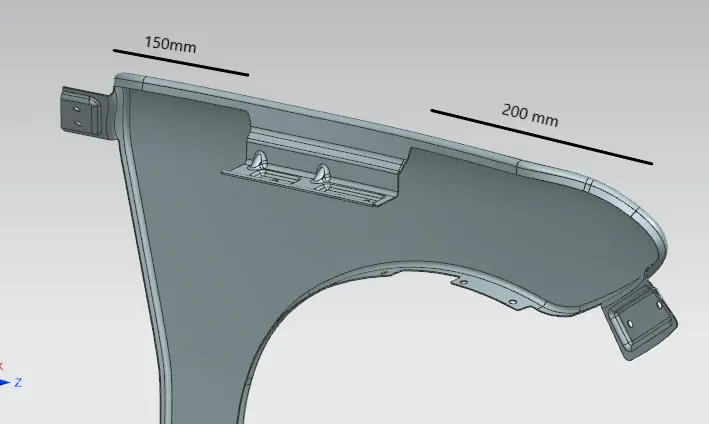
- The height of drip area mounting should be less than 40mm so that it reduces the springback effect during manufacturing and reduce NVH issues during vehicle movement.
- Mounting screw holes of dia 5mm are and locator pin holes are created for mounting guidance.
- It should be distanced atleast 150mm from the front side ande 200m from the rear side .
- Ribs are to be provided in order to increase the strength of the mounting part .
- Embosses are created as per design standards for proper fixation.
A-pillar design
The A-pillar area mounting depends upon the A-pillar of the car .
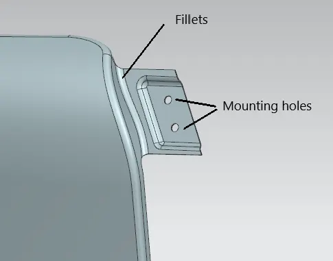
- Fillets are provided for easy manufacturability
- A- pillar fender flange is created as per design standards with two bolting holes
Bumper area Design
This is designed by consulting the bumper design team to design the bumper and fender assembly fixation.
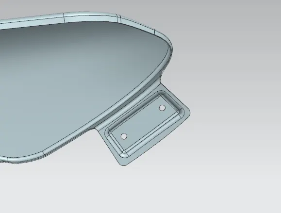
- Two Bolting holes with embosses are created for approapriate assembly.
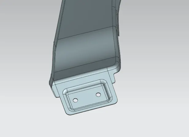
Sill area mounting Design
Sill area mounting is also an important mounting part .This mounting point is basically on the bottom of the fender . The mounting part should be created such that the fender is firmly attached to the sill to avoid NVH issues.
Baffle Mounting area Design
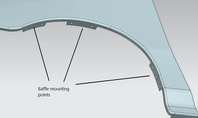
- For improvement of NVH in car , usually a baffle is mounted on the fender of the car . it is mounted on the wheel arch area .
- Embosses are not needed since it is a free end which is not main attachment to the body of the car.
Result:
A thickness of 0.75mm is given to the surface to produce solid body
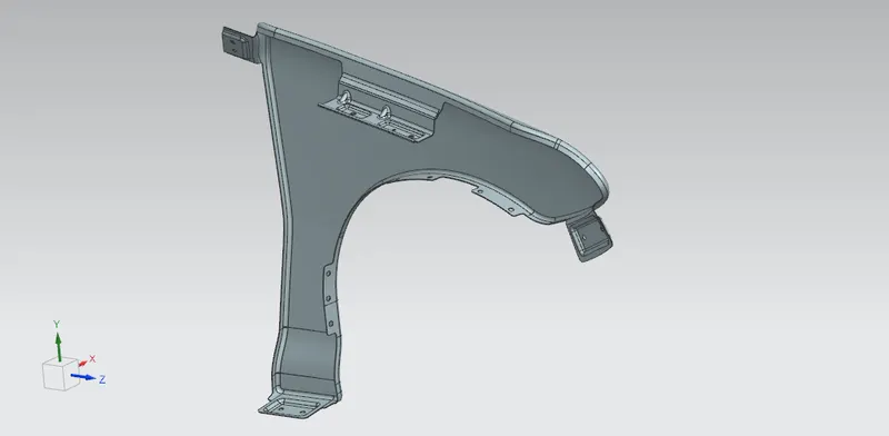
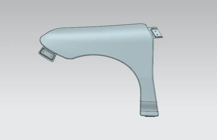
Rendered Image
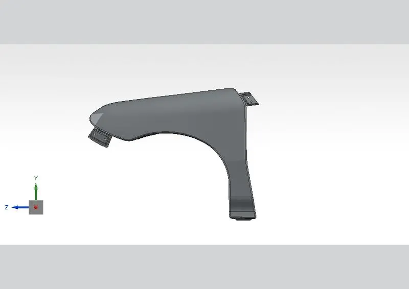
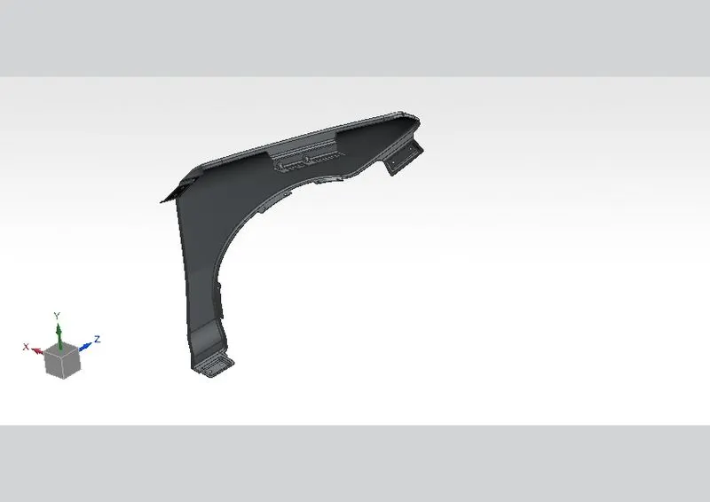
Commands used from NX CAD to model this fender are:
- Offset in face
- Curve on surface
- Trim sheet
- Law extension
- Datum plane
- Intersection curves
- Face blend
- Bridge curve
- Sketch
- Projected curve
- Emboss
- Edge blend
- Sew
- Dart
- Thicken
Conclusion:
The fender of the automobile is checked for the wheel arch radius as per Europen regulations and designed the front half fender of a car using master section and by following the pedestrian's safety and in order to guard the engine compartment and beside the vehicle.