Week 4
Aim:
- To check and correct geometry errors in the given bottle cap component.
- To mesh the given component and assign thickness.
Procedure:
- Performing a topology for the given whole component to stitch any uneven joints and check the quality
- From the ‘checks’ option geometry check is followed for visible errors.
- Any errors such as ‘crack between cons , needle face, triple cons’ can be auto fixed or deleted to fix the geometry error. It is repeated until no error is found for all property components.
- Any auto unfixed shall be addressed manually by each entity in error till no geometry error occurs.
Midsurfacing
- Each macro area or part is isolated separately using the ‘AND/ INOT’ command and locking it in multiple lock views for convenience.
- Each feature is taken mid surface using ‘Faces-Middle or Offset' command.
- While using the ‘offset’ command , the thickness of the features is measured accurately using the ‘measure’ command to take the exact midsurface.
- The entire midsurface taken can be isolated by the ‘NOT-PID region’ command
- Each mid surface feature is attached to the nearer parent midsurface using ‘extend/new’ etc. as shown below (blue triple cons are formed on the extended joint surface)
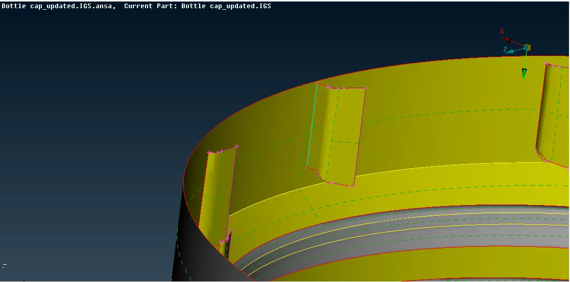
- ‘Curves-middle’ option is used on some features to create a new mid surface as shown below (threads inside the bottle cap)
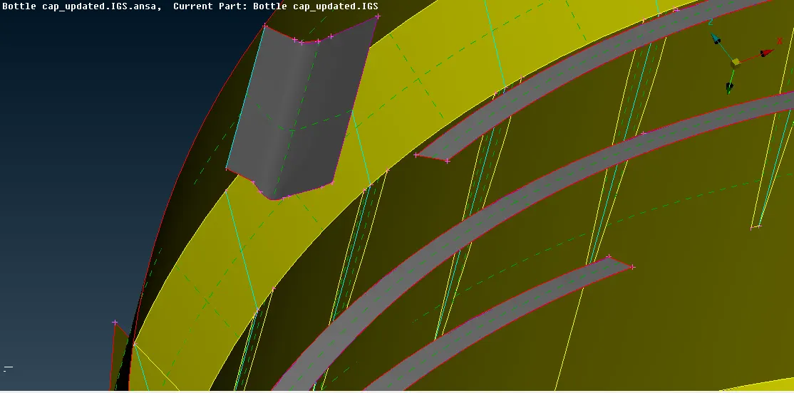
- Similarly, different features’ midsurface is taken likewise using these various methods.
- To check whether the mid surface has fallen in the centre visually , turning on transparency of the parent body and viewing it in ‘PID’ view will do the job as shown below.
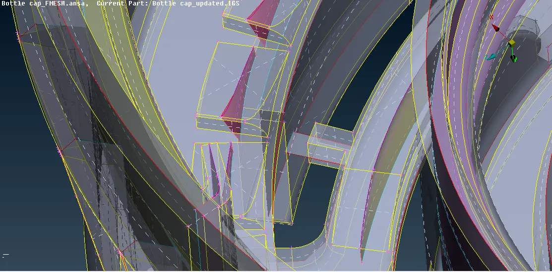
- Setting a separate Property ID for the total midsurface using ‘Set PID’ command As "Total Midsurface"
Meshing
- Each element can be isolated separately or collectively for convenience of meshing view.
- Length of the mesh elements is changed to ‘1’ by selecting ‘macros-length’ selecting all.
- The given Quality criteria such as ‘ min length, skewness, aspect’ etc. is fed into the quality check box
- ‘Mesh’ panel is selected near ‘Topo’ for meshing options
- The construction lines are deleted / adjusted using the ‘cut/delete’ macros option
- The construction lines edges of the component are adjusted to cover of the edge since given lines could fail on mesh element size quality criteria.
- Section by section meshing is done using ‘Shell mesh- Best’ command
- ‘Shell mesh - Reconstruct’ is used to refine the mesh flow on the selected area by using different selecting options (Macro area/ PID/ entity etc.)
- Switch the view to ‘Hidden’ in the bottom panel to check for quality criteria .
- Any failure of parameters is shown on respective colors to the mesh elements.
- Failure errors can be resolved by various methods such as adjusting the construction lines , reconstruction/reshape of the mesh, splitting/ joining/swapping of elements to eradicate the failures.
- Quality of the mesh flow/ physical structure can be compromised in the area of constraints as shown below (skewness/wrapping errors are removed using ‘cut’ option as resulted below)
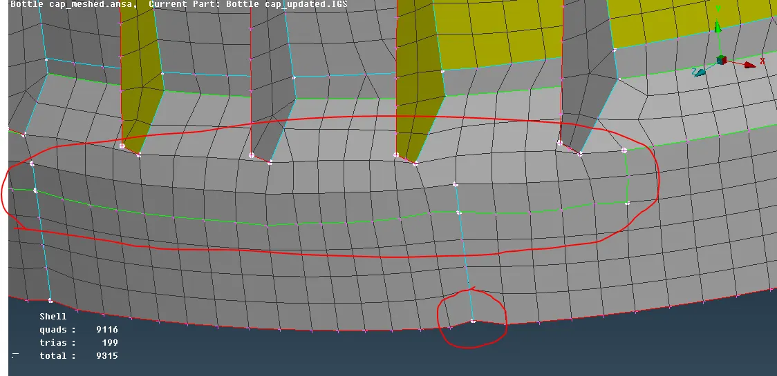
- The data panel on the workspace shows the number of quad, tria, total and off elements. (there will be no ‘off’ if there is no failure in quality)
- The inevitable failure shown below is caused because of aspect ratio criteria which cannot be avoided in those regions. (Since mid length of the feature cannot be changed cause aspect failure)
-
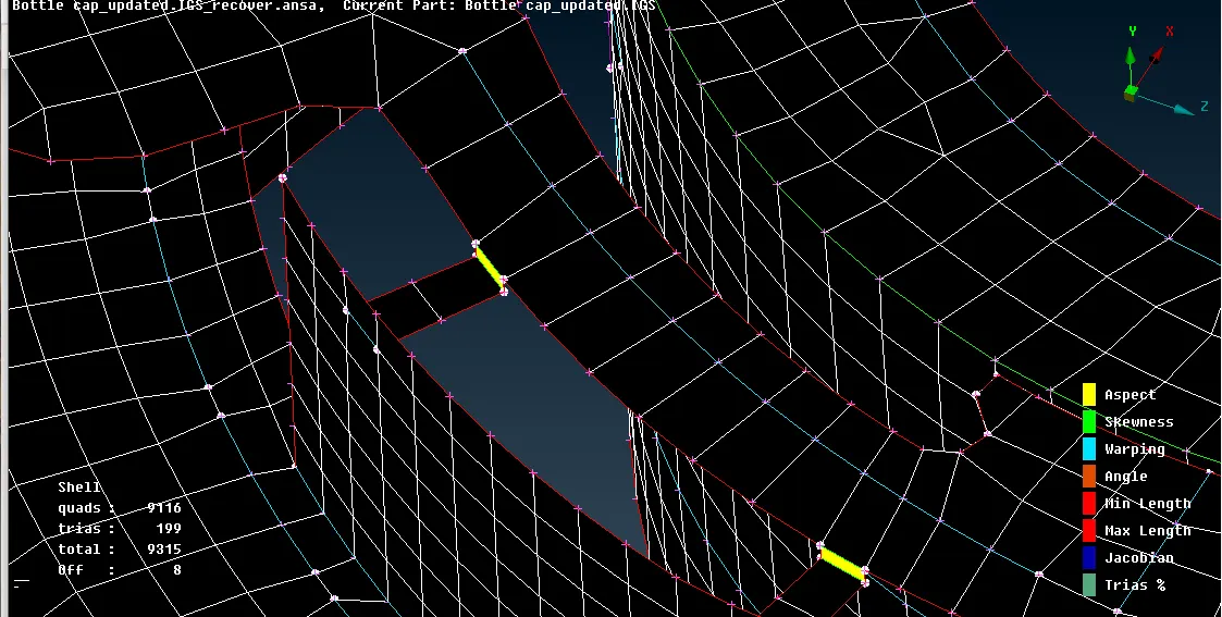
- The process is repeated to achieve a proper visual and efficient mesh flow on the surface.
Learning Outcomes:
- Triple cons and its nodes cannot be removed as construction lines for meshing convenience in mesh grid view
- ‘Paste’ option can be used to connect trias to form quad elements and smoothening it using ‘smooth’ option
- ‘Curves- create/middle’ etc. option is more efficient on complex features to create midsurface.
- Individual mesh elements can be addressed better with the ‘Split’ and ‘swap’ option.
Conclusion:
- In conclusion, smooth mesh flow is required on the component without patterns to prevent disruption of results in solving after preprocessing which should be done as quickly and in the best quality as possible for better efficiency of work with few comprise of the quality due to inevitable constraints.